

Groove Tubes Glory Reference Manual
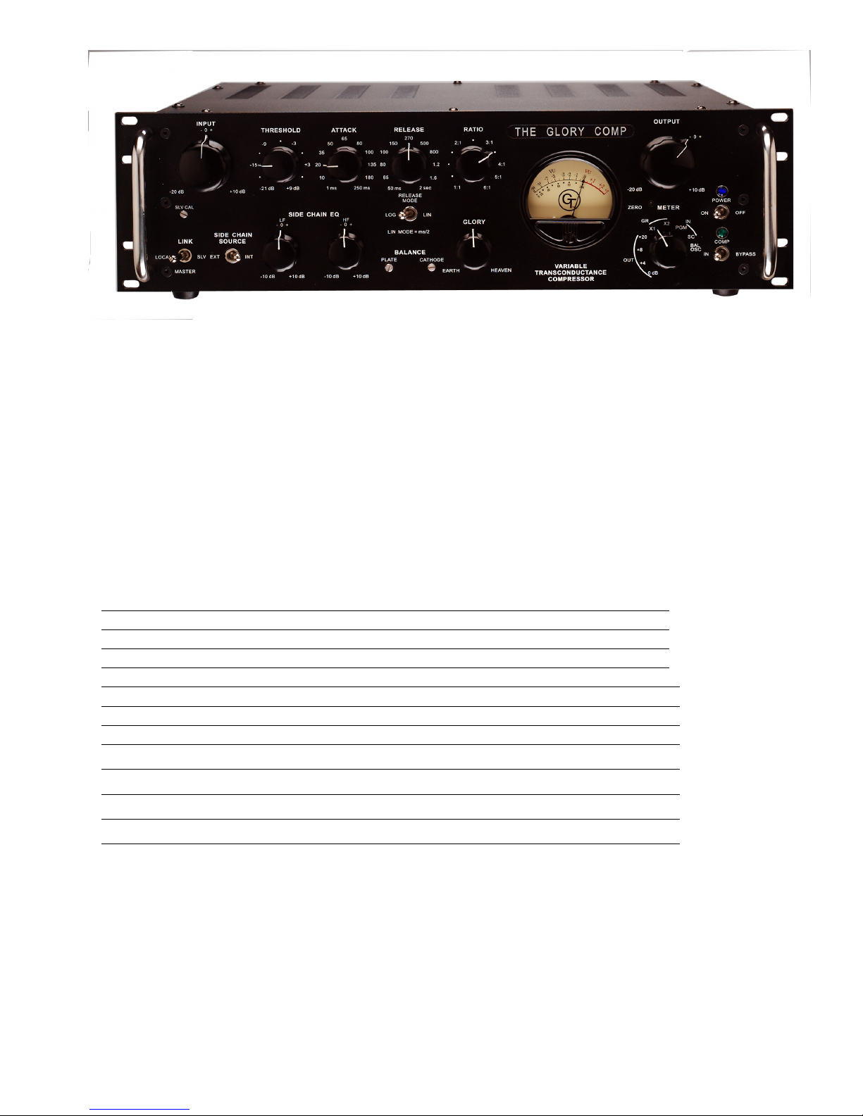
The Groove Tubes
Glory
Co mpressor
Reference Manual
5/16/2006 REV 6
Table of contents 1
Introduction 2
Safety Instructions 4
QUICK START guide 7
Front Panel Features and Controls _ 11
Other Recessed Controls 21
Rear Panel Features 22
Special Refinements Under the Hood 25
Unpacking and Inspection 32
Specifications 33
Obtaining Repair Service 36
Groove Tubes Limited Warranty 37
- 1 -

INTRODUCTION:
THANK YOU, for your purchase of the Groove Tubes Variable
Transconductance Glory Compressor.
Please read over this manual carefully as it contains
information essential to the proper operation and maximum
enjoyment of this dynamics controller.
The Glory Compressor is designed to provide suitable
downstream dynamics processing when paired with the GT VIPRE,
or any other professional audio source, and furnish maximized
sonic performance coupled with a generous ability to wrap
itself around the dynamic content of any signal source you may
wish to transform.
With the Glory Compressor’s feature compliment, you no longer
have to settle for what a given audio signal sounds like with
a low-headroom solid-state dynamics controller, or be boxed-in
by limited side-chain control options.
The Glory Compressor is designed to be flexible, and to adapt
to accommodate your situation, rather then the other way
‘round. To this end you will notice that it is the
anticipation of your compressor applications, which has driven
every detail of the Glory Compressor’s planning, engineering,
feature set, operating convenience and adaptability.
UNPACKING
Unpack the compressor carefully and make sure that all
supplied accessories are present. Examine all items for any
possibility of shipping damage. All seven tubes should be
standing at attention in their sockets. If the compressor is
damaged or fails to operate, notify the shipper and your
dealer or us immediately. Or if the compressor was shipped to
you directly, notify the shipping company without delay.
Your Glory Compressor was packed with the following
accessories:
A. 1 each rack-mount bracing kit.
L/R pair of rack mounting braces, which can be attached to the
sides of the Glory chassis, and rack mounted I RU above the
Glory front panel. This brace provides both rear chassis
- 2 -

support as well as insuring good ventilation for the top of
the Chassis.
B. 1 each 6 foot IEC 3-conductor power cable.
C. 1 each Owner’s manual.
Note: It is prudent to retain the shipping materials
for future use, as these materials are custom formed for
the Glory Compressor and will greatly minimize the
chance of shipping-related damage.
- 3 -
Important Safety
Instructions
Safety symbols used in this product:
This symbol alerts the user that there are important
operating and maintenance instructions in the literature
accompanying this unit.
This symbol warns the user of un-insulated voltage
within the unit that can cause dangerous electric shocks.
This symbol warns the user that output connectors
contain voltages that can cause dangerous electrical
shock.
Please follow these precautions when using this product:
1. Read these instructions.
2. Keep these instructions.
3.Heed all warnings.
4.Follow all instructions.
5.Do not use this apparatus near water.
6. Clean only with a damp cloth. Do not spray any liquid
cleaner onto the faceplate, as this may damage the front panel
controls or cause a dangerous condition.
7. Install in accordance with the manufacturer's
instructions.
8.Do not install near any heat sources such as radiators, heat
registers, stoves, or other apparatus (including amplifiers)
that produce heat.
9. Do not defeat the safety purpose of the polarized or
grounding-type plug. A polarized plug has two blades with one
wider than the other. A grounding-type plug has two blades
and a third grounding prong. The wide blade or the third
- 4 -
prong is provided for your safety. When the provided plug
does not fit into your outlet, consult an electrician for
replacement of the obsolete outlet.
10. Protect the power cord from being walked on or pinched,
particularly at plugs, convenience receptacles, and the point
where they exit from the apparatus.
11.Use only attachments or accessories specified by the
manufacturer.
12.Use only with a cart, stand, bracket, or table designed for
use with professional audio or music equipment. In
any installation, make sure that injury or damage
will not result from cables pulling on the
apparatus and it’s mounting. If a cart is used,
use caution when moving the cart/apparatus combination to
avoid injury from tip-over.
13. Unplug this apparatus during lightning storms or when
unused for long periods of time.
14. Refer all servicing to qualified service personnel.
Servicing is required when the apparatus has been
damaged in any way, such as when the power-supply
cord or plug is damaged, liquid has been spilled or
objects have fallen into the apparatus, the apparatus has been
exposed to rain or moisture, does not operate normally, or has
been dropped.
15. This unit produces heat when operated normally. Operate
in a well-ventilated area with at least six inches of
clearance from peripheral equipment.
16. This product, in combination with an amplifier and
headphones or speakers, may be capable of producing sound
levels that could cause permanent hearing loss. Do not
operate for a long period of time at a high volume level or at
a level that is uncomfortable. If you experience any hearing
loss or ringing in the ears, you should consult an
audiologist.
- 5 -

17. Do not expose the apparatus to dripping or splashing. Do
not place objects filled with liquids (flower vases, soft
drink cans, coffee cups) on the apparatus.
18. WARNING: To reduce the risk of fire or electric shock, do
not expose this apparatus to rain or moisture.
CE Declaration of Conformity
Manufacturer’s Name: Groove Tubes llc
Manufacturer’s Address: 1543 Truman Street
San Fernando, CA
91340
USA
declares, that the product:
Product Name: Glory Comp
Model Type: Variable
Transconductance Tube Compressor
conforms to the Standards for Safety and EMC for this product listed on
the Internet site:
www.groovetubes.com
- 6 -

Quick Start Guide
Step 1: Preliminary inspection.
Remove the Glory Compressor from the package and carefully
inspect the unit for outward signs of damage or distress. All
projecting controls and connectors should operate smoothly and
uniformly, and the enclosure’s surfaces should be free of
irregularities. All seven tubes should be standing at
attention in their sockets. Contact your dealer, the shipper
or us without delay if there is evidence of damage to the
unit.
Step 2: Park it.
Budget a suitable space to install the unit in an equipment
rack. Make sure there is at least 1U of breathing space above
and below the compressor, and that the airflow in the rack is
not constricted, since there will be about 95 Watts of power
dissipated by the unit. Keep cables and other objects away
from the rear panel and heat-sink since this panel will get
rather warm during operation.
Step 3: Hook it up, front panel control initial start-up
positions.
A. Route the target signal to either the INPUT XLR or TRS
jack. The TRS input jack will exhibit 6 dB more sensitivity
then the XLR input. Apply a 0 VU (+4 dBu, 1.23 Vrms) signal to
the XLR jack, or a -6 VU (-2 dBu, about 600 mVrms) signal to
the TRS jack. Using the TRS input jack will interrupt any
signal applied to the XLR input jack. Both jacks present
bridging loads to the line input signal, of about 10k and 20k
ohms respectively, and both are actively balanced.
B. Route the processed signal from the unit via the PROGRAM
OUTPUT XLR plug or TRS jack to suitable line-level monitoring
and/or recording gear. Be careful not to connect the
compressor outputs to any microphone-level inputs not capable
of handling large line-level signal levels. Damage to the misconnected microphone preamp may result.
C. Connect the compressor to the correct line voltage using
the supplied IEC power cable.
D. Turn the power on. Power lamp blinks during 30 second
warm-up period, and COMP relays hard-bypass the compressor
- 7 -

audio path by tying the like-format PROGRAM INPUT and OUTPUT
connectors together. The green COMP LED remains unlit until
the warm-up period is completed.
Notice that the relay-bypass circuit can only connect
like style PROGRAM connectors together, i.e., XLR in
to XLR out, and TRS in to TRS out. For example, if the
XLR PGM input is being used and the bypass mode is asserted,
no pass-through signal will be heard on the TRS PGM output
jack. In this case, the pass-through signal will be heard at
the XLR PGM output.
Step 4: front panel control initial start-up positions.
Position the front panel potentiometers and switches at the
following starting points:
INPUT = 0 Db,
THRESHOLD = -15 dB,
ATTACK = 35 ms,
RELEASE = 150 ms,
RELEASE MODE = LOG
RATIO = 1:1 (compression disabled),
OUTPUT = 0 dB,
METER = IN,PGM position,
COMPressor (hard-wire bypass switch) = IN,
LINK = LOCAL,
SIDE CHAIN SOURCE = INT,
SIDE CHAIN EQ LF = 0 dB, HF = 0 dB, and
GLORY = EARTH.
After the 30-second warm-up period, the compressor’s VU meter
should show PGM IN activity derived from the signal hitting
the PROGRAM INPUT jacks, and, if the COMP switch is in the
“IN” position, the green COMP LED will illuminate. Adjust the
INPUT control to get an average VU meter reading of 0 if need
be. It is OK if the meter gently hits the positive end-stops
on signal peaks; the compressor input circuitry has lots of
headroom. The uncompressed signal should be audible at the
PROGRAM OUTPUT jacks. Then:
A. Rotate the METER switch to the OUT, +8 position, or
whichever position best suits your production plant’s
operating level. The soon-to-be processed (output) signal
level should be visible on the VU meter and audible on any
attached outboard monitoring gear.
- 8 -

Notice that the output meter indication reflects the
actual signal present at the XLR PROGRAM OUTPUT plug, in
actual 600-ohm dBm units, when a 600 ohm load is present. The
reading will change somewhat depending on downstream load
conditions. If the load is light (say 10 k-ohms), the meter
will read at a somewhat higher level then if the load was
precisely 600 ohms. If the load is short-circuited, the meter
will read below -20 VU (no movement).
B. Rotate the METER switch to the GR, X1 position.
The meter should rest at the zero VU mark after 10 – 15
minutes of warm-up time (or you may adjust zero-trim at powerup if desired, but it may need to be touched up on the way to
temp stabilization), and now indicates the amount of gain
reduction, in dB, which should be zero since the RATIO switch
is still at the 1:1 position. The 1:1 ratio is included in
order to allow an audition of the signal path without dynamics
processing.
Notice that the zero-trim interacts with the GR meter
circuits only, and not the on-line audio signals.
The GR X2 position doubles the VU meter’s indicated amount of
GR, where a reading of -5 becomes -10 and so forth.
Rotate the RATIO switch slowly clockwise, stopping at 3:1.
The meter should deflect downward away from the zero mark,
depending on the volume of signal exceeding the THRESHOLD
setting of -15 dB. Notice that the THRESHOLD switch
calibration marks are referred exclusively to the IN-PGM VU
meter zero mark. In this case, compression will begin for
signal levels that exceed -15 VU when the METER switch is in
the IN-PGM level-reading position.
Notice that the VU meter, in typical fashion, may not
show large amounts of downward deflection when
responding to compression of fast or staccato signals,
such as rim-shots and the like. Also, the total amount of GR
displayed will be reduced by long ATTACK or short RELEASE
time, since these types of settings reduce the magnitude of
the control voltage produced by the side-chain circuitry.
At this point, the compressor should be actively reducing the
amplitude of the target signal. The user may now begin to
- 9 -

explore the various control settings, and arrive at those
which best suit the signal to be processed.
Note: Gain Reduction meter stabilization (GR x1 and x2)
Glory needs about 30 minutes of warming before the GR meter
will stabilize to read “0”. When turned on, the meter will
typically read a dB or so more than “0” until it fully warms
and stabilizes. Meanwhile, this temporary condition will not
affect Glory’s audio performance in any way OR affect the
operational mode of the meter when showing gain reduction. You
may wait for the meter to net itself in as the unit warms up,
or of course it is possible to continually trim the meter to
“0” until fully warmed up. Unless time pressure prevents it,
we suggest that you trim the GR “0” setting when the Glory is
fully warmed up, and let the meter reach “0” during future
sessions.
- 10 -

Front Panel Features and
Controls
A brief description of the control functions follows. The
fundamental ideas will be well-known to those who have spent
time with dynamics controllers used for audio production, but
there are a number of new twists and features that make an
examination of this section profitable.
The usual suspects
The Glory Compressor incorporates many familiarly labeled
controls, as may be found when comparing the control family
with those appearing on recent models of solid-state dynamics
processors. Indeed, the attractive and flexible dynamicscontrol array found on modern and certain vintage compressors
did in part inspire the control complement for the Glory Comp.
The feature twist here is the objective of providing userselectable parametric time and level control flexibility in an
all-tube compressor. Tough, but do-able.
INPUT potentiometer and THRESHOLD rotary switch.
Do just what they say. The INPUT control
provides program signal input level scaling,
from –20 dB of attenuation, to +10 dB of
gain. It is used to adjust the program input
level, until the average level provides
ample input INput-ProGraM VU meter
deflection with averages hovering about the
0 dB mark.
The THRESHOLD control may then be used to
set the level of the compression knee, with
compression effects commencing when input
signals exceed the chosen knee voltage. The
control’s calibration is referenced to the
PGM meter zero VU deflection mark. Unlike
most modern fixed-knee compressor designs,
the separate THRESHOLD compression knee control permits
flexibility over the indicated range, independent of the Input
control setting. Notice that the chosen compression ratio will
be reached at a signal level at about 2 dB over that indicated
by the THRESHOLD switch setting.
- 11 -
The independent RATIO and THRESHOLD controls permit
interesting and subtle application of the compressor, by, for
example, setting the knee at very low signal levels (-21 dB),
and applying very shallow compression RATIOs of, say, 1.5:1.
The user may then reach deeply under the peak dynamic events
in the program signal, and give subtle added thickness to
material starting at more than 20 dB BELOW the peak program
operating level. Useful for raising foreground sound minutiae
and elevating room ambience details.
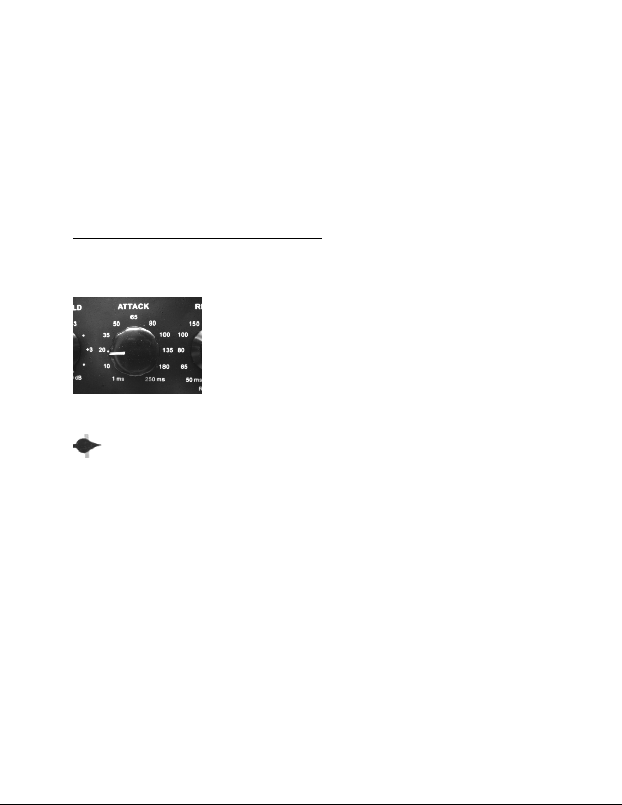
ATTACK and RELEASE rotary switches
ATTACK rotary switch
Each of these two controls function
conventionally, with separate time-constant
circuit stages dedicated to each control.
The ATTACK control sweeps through an
approximately 250:1 adjustable timeconstant range. The expanded 1 to 100 ms
mid-values correspond to the range of
average time intervals required for the
human ear to respond to an impulsive signal.
Note however that a 1 millisecond transient will
correspond to nearly 100 sound samples in a 96 kHz
digital system. Which means it will still be possible to clip
digital systems briefly, even with the ATTACK time set to
minimum. Occasional slight clipping of a 1 ms interval of
program material in a well designed digital system will be
inaudible, and may be avoided by modest drive level reduction
to the digital system.
The ATTACK and RELEASE controls are best set to values that
fit the particular musical situation. By “fit” it is meant
that, in general, faster A&R settings for percussive signals
where there is little sustain or ambient sound, and slower for
more ponderous acoustic events where there are long decay
intervals from an instrument or room reverberation. Initial
control-setting exploration will be necessary to fit the time
constant controls to the musical events at hand.
To minimize compression artifacts, it is best to keep the
ATTACK control set to time periods equal to ½ or less of the
RELEASE control setting, and both set to intervals longer then
- 12 -
 Loading...