

Page 1
1
Picnic Table Bar Top
1
3
7
6
5
4
2
(39” x 39” x 42”H) Assembly Instruction
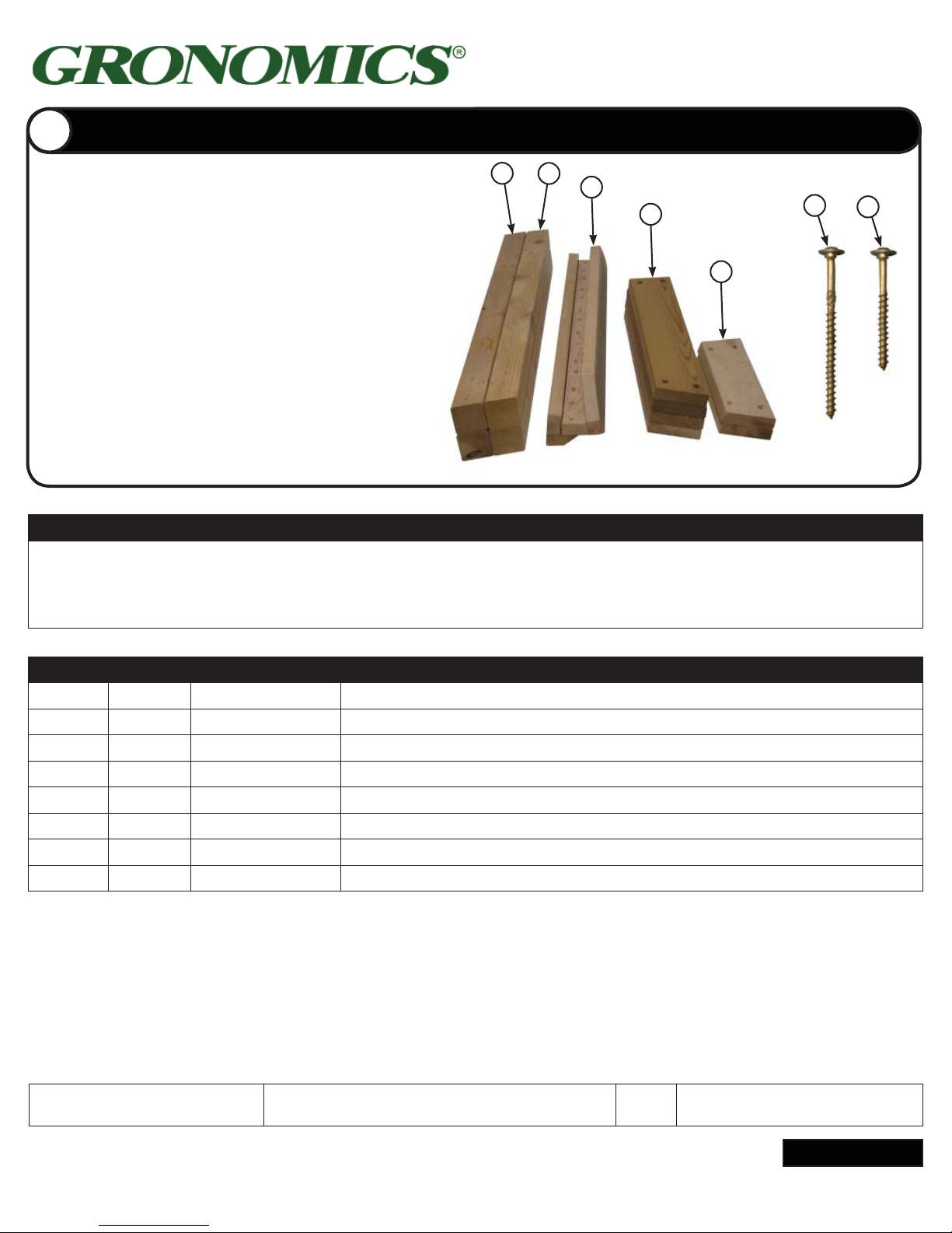
Parts Identifi cation Box 1
Stack matching pieces in piles. Using the
parts list, locate and count the individual
pieces and verify that you have received
Item #: PTBT 39-39
Torx® T30
the correct number of pieces.
If any pieces are missing or replacement
parts are required, contact Gronomics at
1-855-299-6727.
NOTE: It is recommended to place a
protective layer between the ground and
the pieces during assembly. This will help
prevent damage to the pieces.
Product Care & Maintenance
Western Red Cedar will turn a weathered grey if left unfi nished. Although no fi nish is required for cedar when used outdoors,
a natural oil fi nish applied regularly will help maintain the beauty and minimize cracking and drying. It is recommended
to use Gronomics Garden Bed Oil (Item# GBO-1Q), a non-toxic, food safe fi nish that is very easy to apply.
Apply oil when air and wind temperatures are between 50-90 degrees. Avoid applying in direct sunlight.
Box 1 of 2
ITEM QTY. PART # DESCRIPTION
1 2 PTBT4200-X Corner Posts, 3-1/4” x 3-1/4” x 42” (X)
2 2 PTBT4200-O Corner Posts, 3-1/4” x 3-1/4” x 42” (O)
3 2 TTSB2638 Table Top Side Braces, 2” x 6” x 38” With 2 x 2 x 38” Cleat
4 4 TTLLB2624 Table Top Lower Leg Braces, 2” x 6” x 24-1/2”
5 2 TTULB2615 Table Top Upper Leg Braces, 2” x 6” x 15”
6 32 RSS516-4ZY GRK RSS Screws, 5/16” x 4”
7 28 RSS516-212ZY GRK RSS Screws, 5/16” x 2-1/2”
Packaged & Inspected by: Date:
Continued
www.gronomics.com East Bethel, MN USA 763-753-7374
Page 2
2
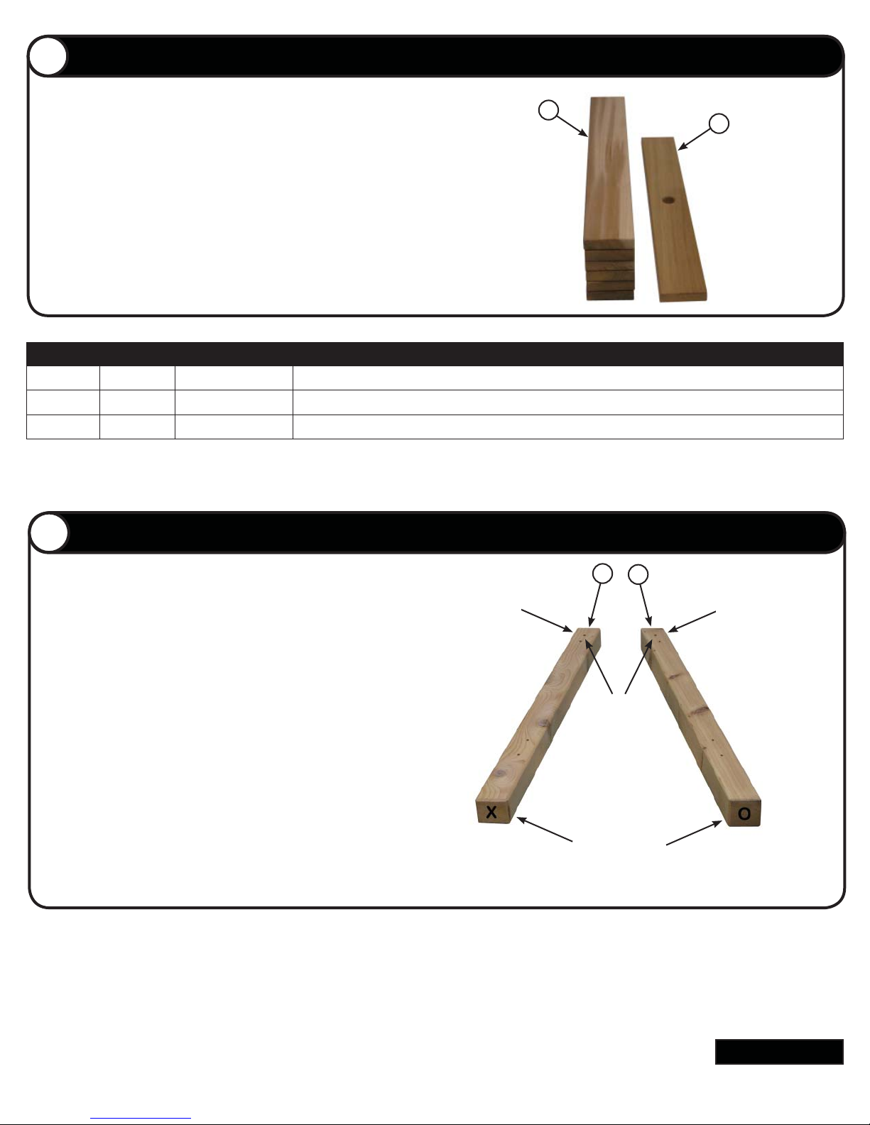
Parts Identifi cation Box 2
9
8
3
1
2
Remove contents from Box 2 of 2.
Stack matching pieces in piles. Using the parts list,
locate and count the individual pieces and verify that
you have received the correct number of pieces.
NOTE: It is recommended to place a protective layer
between the ground and the pieces during assembly.
Box 2 of 2
ITEM QTY. PART # DESCRIPTION
8 6 TTP2639 Table Top Panels, 2” x 6” x 39-1/2”
9 1 TTCP2639 Table Top Center Panel w/Hole, 2” x 6” x 39-1/2”
Corner Post Assembly
NOTE: Do not fully tighten screws on legs and side braces
during assembly.
NOTE: Once the leg assembly is completed and table is
placed on a level surface fully tighten screws.
Locate one 3-1/4” x 3-1/4” x 42” corner post labeled “X”
(Item 1) and one corner post 3-1/4” x 3-1/4” x 42” labeled
“O” (Item 2). Place the two corner posts on the ground
with the X & O located as shown. The two pre-drilled holes
facing up and two pre-drilled holes facing to the outside (at
the top of the corner posts).
NOTE: The two pre-drilled holes at the top of the corner
posts (facing up) (opposite of the X & O) should be farther
down and closer together than the two pre-drilled holes
located to the outside.
Pre-drilled Holes
Located to the
Outside
Pre-drilled Holes
Facing Up
Bottom of Corner Posts
Pre-drilled Holes
Located to the
Outside
Continued
www.gronomics.com East Bethel, MN USA 763-753-7374
Page 3
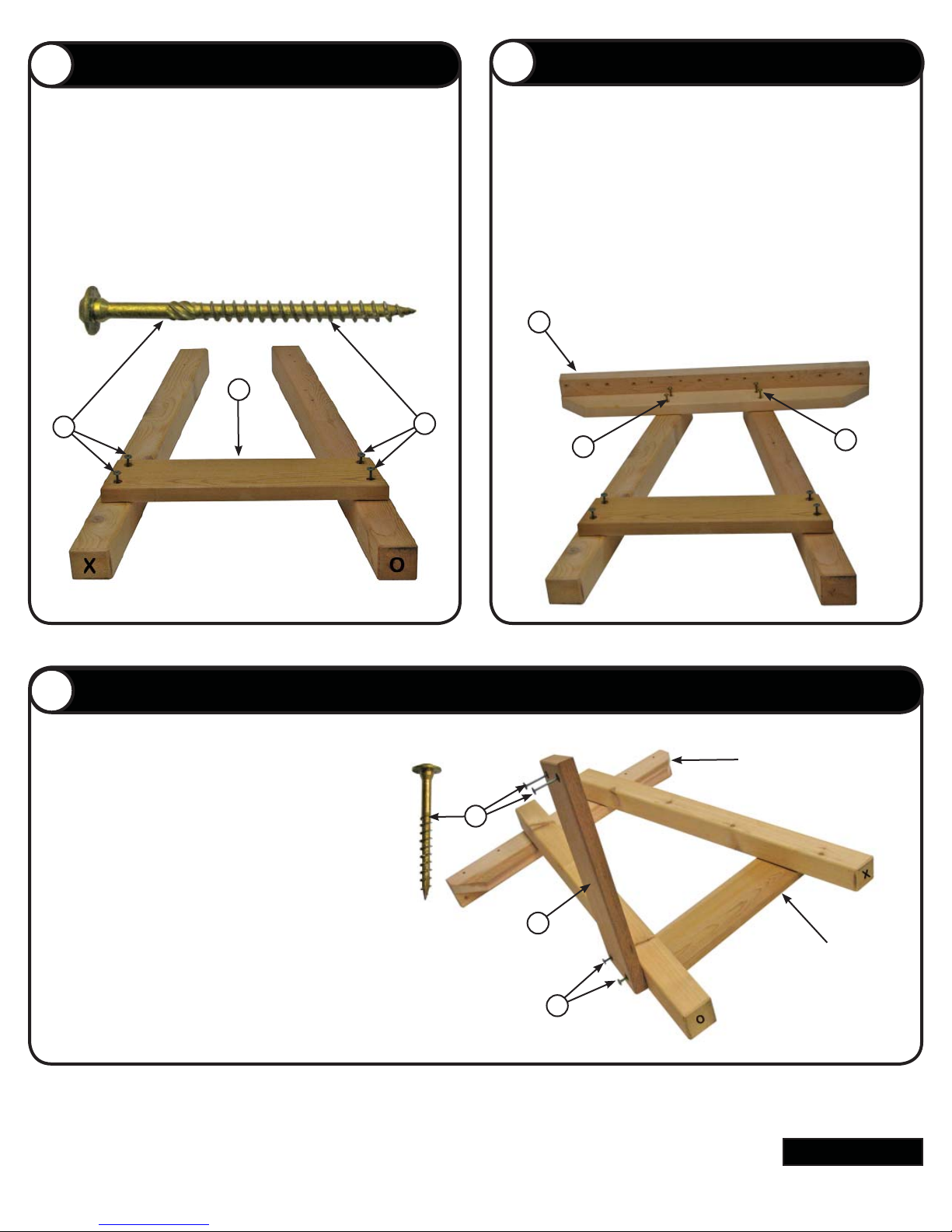
Lower Leg Brace Assembly
4
4
6
6
5
3
6
6
6
4
6
6
Side Brace Installation
Locate one 2” x 6” x 24-1/2” lower leg brace (Item 4). Install
four 5/16” x 4” screws (Item 8) in the pre-drilled holes of the
lower leg brace.
Align the lower leg brace & screws with the pre-drilled holes
in the two corner posts. Tighten screws fi rmly but do not
fully tighten.
Install four 5/16” x 4” screws (Item 6) in the pre-drilled holes
of the 2” x 6” x 38”side brace assembly (Item 3).
Install the side brace as shown. Align the side brace &
screws with the pre-drilled holes in the two corner posts.
Tighten screws fi rmly but do not fully tighten.
Repeat steps 2-4 for the other leg assembly.
7
Lower Leg Brace Assembly Continued
Place one of the leg assemblies on the ground
with the lower leg brace & side brace facing
down (as shown).
Install four 5/16” x 4” screws (Item 6) in the
pre-drilled holes of a 2” x 6” x 24-1/2” lower leg
brace (Item 4).
Align the lower leg brace & screws with the predrilled holes in the corner post. Tighten screws
fi rmly but do not fully tighten.
Side Brace
Lower Leg Brace
Continued
www.gronomics.com East Bethel, MN USA 763-753-7374
Page 4
7
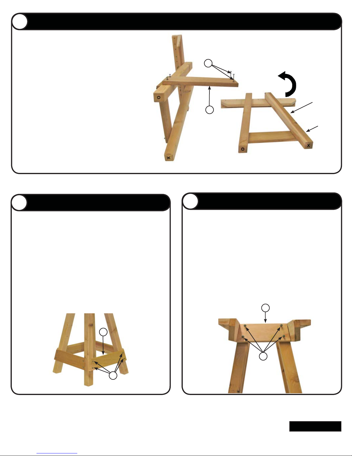
Leg Assemblies
4
6
8
6
4
9
5
6
Place the leg assemblies on the ground (as
shown).
Rotate the leg assembly shown on the right up.
Align the lower leg brace (Item 4) and screws
(Item 8) with the pre-drilled holes of the leg
assembly on the right.
Rotate This
Side Up and
Align Lower Leg
Brace Holes With
Lower Leg Brace
Located on Left
Leg Assembly
Tighten screws fi rmly but do not fully tighten.
Final Lower Leg Brace Assembly
Stand the leg assemblies up (as shown).
Locate the one remaining 2” x 6” x 24-1/2” lower leg brace
(Item 6). Install four 5/16” x 4” screws (Item 6) in the predrilled holes of the lower leg brace.
Align the lower leg brace and screws with the pre-drilled
holes of the leg assemblies.
Upper Leg Brace Assembly
Lower
Leg
Brace
Holes
Locate the 2’ x 6” x 15” upper leg brace (Item 5). Install
four 5/16” x 4” screws (Item 6) in the pre-drilled holes of the
upper leg brace.
Align the upper leg brace and screws with the pre-drilled
holes of the leg assemblies.
Tighten screws fi rmly but do not fully tighten.
Tighten screws fi rmly but do not fully tighten
Repeat procedure on opposite side with the one remaining
upper leg brace.
Continued
www.gronomics.com East Bethel, MN USA 763-753-7374
Page 5
Side Brace Marking
10
3
11
9
9
10
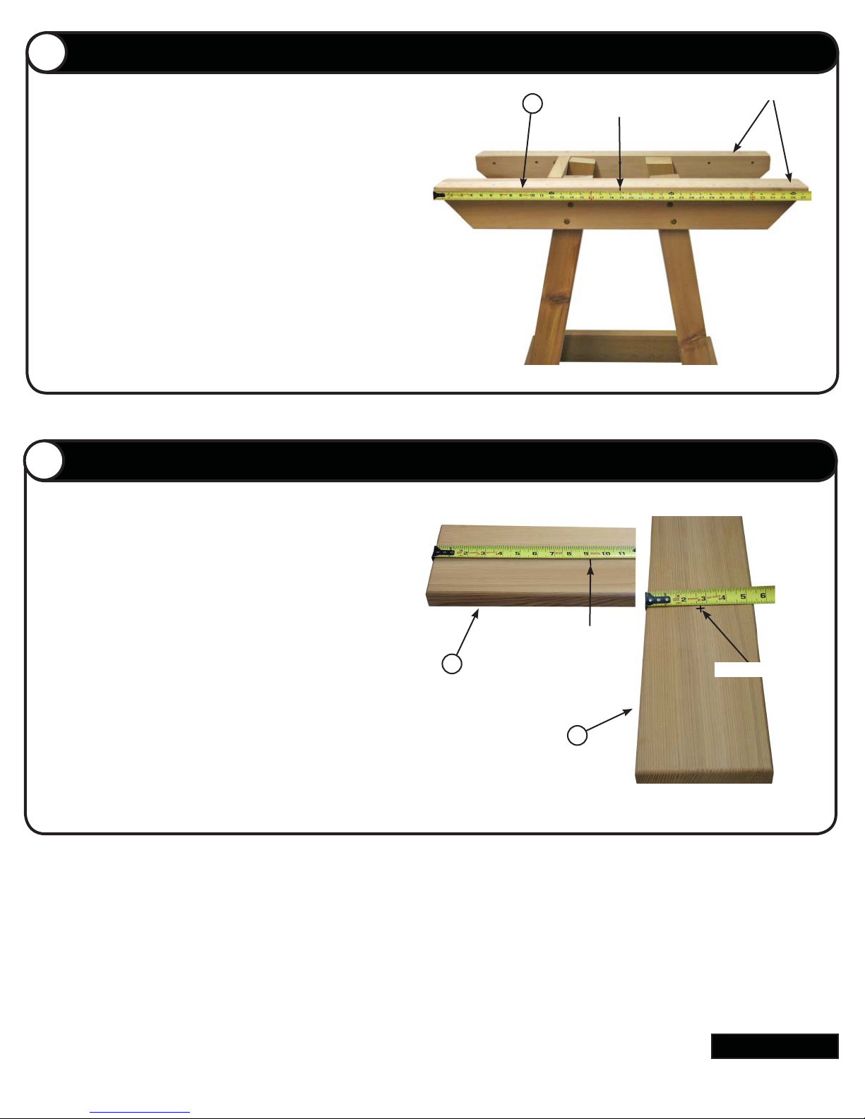
Measure and place a mark at the center of the side brace
(Item 3) (approximately 18-7/8” from the end of the side
brace).
Repeat procedure on side brace on opposite side of assembly.
Table Top Center Panel Marking
11
Side Brace
Place Mark Here
Locate the 2” x 6” x 39-1/2” table top center panel w/
hole (Item 9). Measure 9” from the end of the panel
and place a mark. Then measure across the panel and
place a mark at the center of the panel where the fi rst
mark was made.
Repeat procedure at the other end of table top center
panel w/hole.
Place mark at 9”
Mark center of panel
Continued
www.gronomics.com East Bethel, MN USA 763-753-7374
Page 6
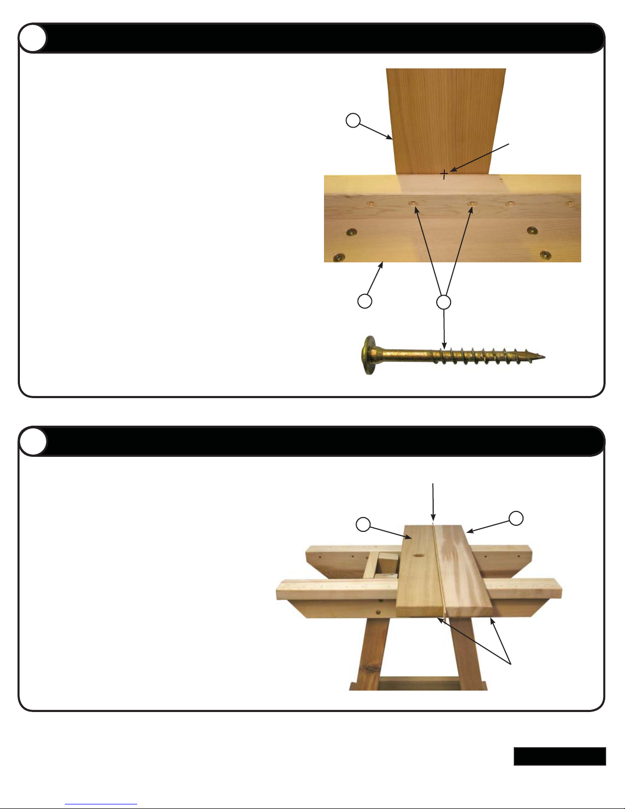
Table Top Center Panel Assembly
10
12
9
3
7
13
9
8
12
Align the center mark of the table top center panel w/hole
(Item 9) with the previous mark on the on the side brace
(Item 3). Move the center panel w/hole in or out until the 9”
mark on the table top center panel w/hole is fl ush with the
outside edge of the side brace.
Align the opposite end of table top center panel w/hole, with
the mark on the other side brace.
NOTE: When both ends of the table top center panel w/hole
are aligned, hold down on the table top center panel w/hole
and install the two 5/16” x 2-1/2” screws (Item 7) into the
pre-drilled holes on each side brace and tighten screws into
the table top center panel w/hole.
Rubber Cap
Align Marks
10
Stud
NOTE: DO NOT over-tighten screws. Over-tightening the
screws will cause the screws to penetrate through the table
top panels.
Table Top Panel Assembly
13
Place a 2” x 6” x 39-1/2” table top panel (Item 8) (as
shown) and align the ends of the table top panel
with the table top center panel w/hole (Item 9).
Place the table top panel spacer (supplied with kit)
between table top center panel w/hole and the table
top panel. Install screws into the table top panel, at
both ends. (See step 12 for screw installation into
table top panels).
Panel Spacer
Remove the table top panel spacer and repeat step
13 for the remaining table top panels.
Align Table Top
Panel Ends
Continued
www.gronomics.com East Bethel, MN USA 763-753-7374
Page 7
Final Picnic Table Bar Top Assembly
14
14
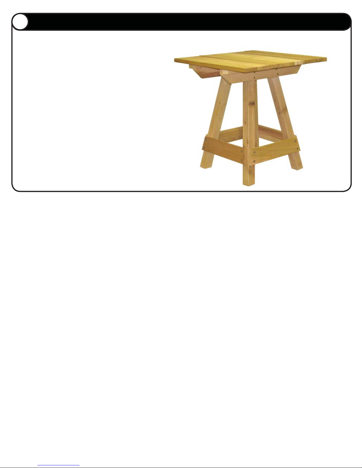
Move the table assembly to the desired location (on the
deck or in the yard). Verify that all four legs are making
contact with the ground.
Completely tighten all screws on the lower leg braces.
Adjust the table top side to side and back to front until the
table top is level. Completely tighten all screws on the side
braces and upper leg braces.
www.gronomics.com East Bethel, MN USA 763-753-7374
 Loading...