

Page 1
1
1 2
11
3 4
13
14
15
16
17
Pergola Planter 18” x 34”
10
9
87
65
12
Assembly Instruction
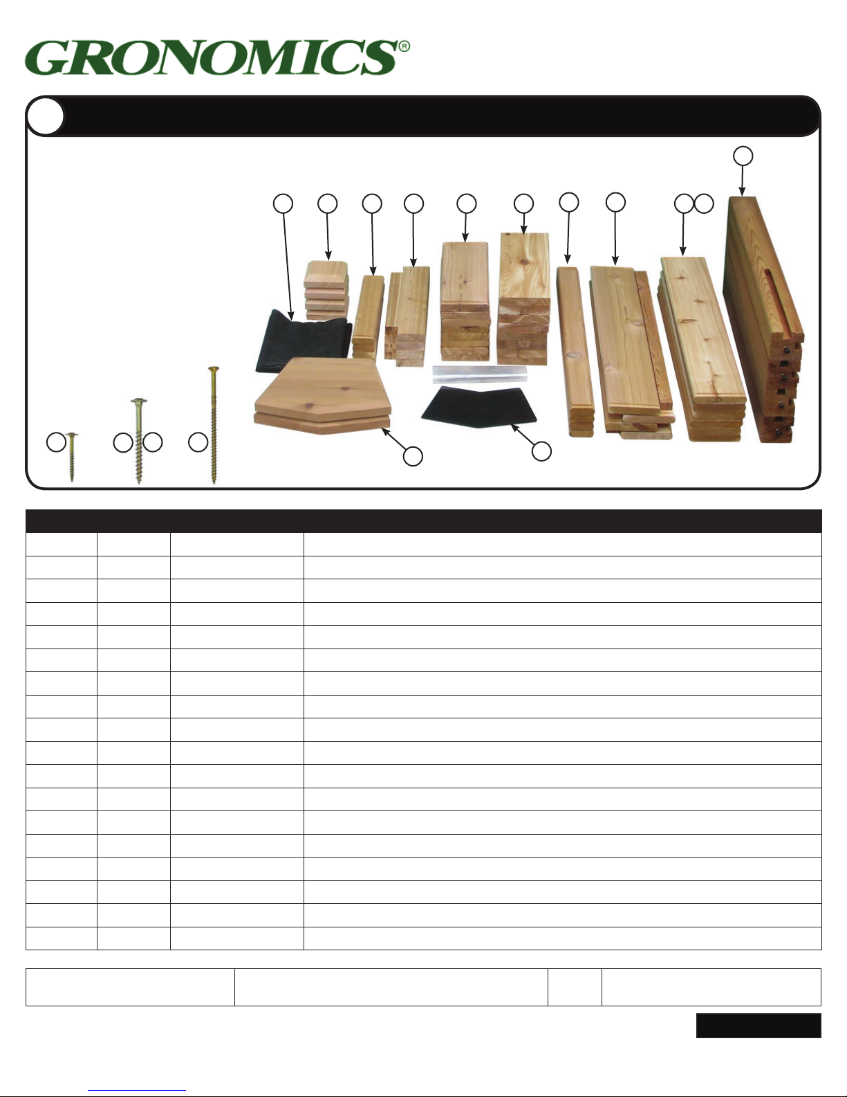
Parts Identifi cation Box 1
Remove contents from Box 1 of 3.
Stack matching pieces in piles. Using the
parts list, locate and count the individual
pieces and verify that you have received
the correct number of pieces.
If any pieces are missing or replacement
parts are required, contact Gronomics at
1-855-299-6727.
NOTE: Ground preparation is optional,
however we recommend leveling area
under frame of product, or place product
directly on a flat level surface before
filling with soil.
Torx® T15
14
Torx® T25
16
15
Torx® T30
17
13
Item #: PP2 18-34
Item #: PP2 18-34S
11
12
10
Box 1 of 3
ITEM QTY. PART # DESCRIPTION
1 2
FL2236
Fabric Liner, 22” x 36”
2 4 3100 Post Cap, 4” x 4” x 1-1/2”
3 4 1451 Narrow Center Side Rail, 14-1/2” x 2-1/2” x 1”
4 4 1551 Corner Notched Bottom Board, 15-1/2” x 4-1/2” x 1”
5 8 1450 Side Rail, 14-1/2” x 5-1/2” x 1”
6 8 1550 Bottom Board, 15-1/2” x 5-1/2” x 1”
7 4 3103 Narrow Center Side Rail, 31” x 2-1/2” x 1”
8 4 3102 Side Rail w/Cleat, 31” x 5-1/2” x 1”
9 4 3101 Side Rail, 31” x 5-1/2” x 1”
10 2 3101L Side Rail w/Logo, 31” x 5-1/2” x 1”
11 4 3201 Corner Post, 4” x 4” x 32”
12 2 7022 Support Plate
13 2 7021 Pentagon Cap
14 12 CS8-112ZY 8 x 1-1/2” GRK Screw (Trellis)
15 20 RSS516-234ZY RSS 5/16 x 2-3/4” GRK Screw (Support Plate)
16 8 RSS516-234ZY RSS 5/16 x 2-3/4” GRK Screw (Posts)
17 12 R410-4ZY R4 10 x 4” GRK Screw (Crosspieces into Trusses)
Packaged & Inspected by: Date:
Continued
www.gronomics.com East Bethel, MN USA 763-753-7374
Page 2
2
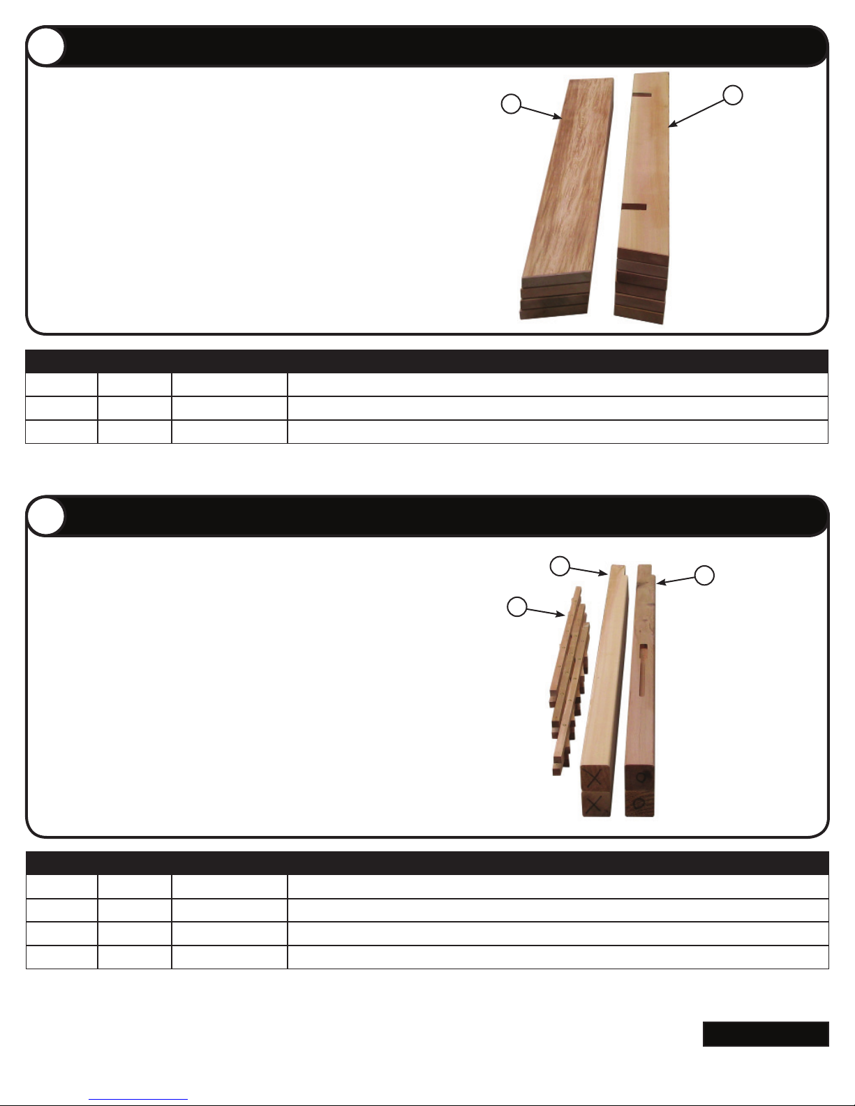
Parts Identifi cation Box 2
19
18
3
20
21
22
Remove contents from Box 2 of 3.
Stack matching pieces in piles. Using the parts list, locate and
count the individual pieces and verify that you have received
the correct number of pieces.
If any pieces are missing or replacement parts are required,
contact Gronomics at 1-855-299-6727.
NOTE: It is recommended to place a protective layer between
the ground and the pieces during assembly. This will help
prevent damage to the pieces.
18
Box 2 of 3
ITEM QTY. PART # DESCRIPTION
18 4 6100
19 6 6102
Truss, 2” x 8” x 61-3/4”
Truss Cross Piece, 2” x 6” x 58”
Long to Short
19
Parts Identifi cation Box 3
Remove contents from Box 3 of 3.
Stack matching pieces in piles. Using the parts list, locate and count the
individual pieces and verify that you have received the correct number of
pieces.
If any pieces are missing or replacement parts are required, contact
Gronomics at 1-855-299-6727.
NOTE: It is recommended to place a protective layer between the ground
and the pieces during assembly. This will help prevent damage to the pieces.
20
21
Box 3 of 3
ITEM QTY. PART # DESCRIPTION
20 2
7023 Trellis, 29” x 52”
21 2 6103-Lt Post, LH, 4” x 4” x 80”
22 2 6103-Rt Post, RH, 4” x 4” x 80”
22
Continued
www.gronomics.com East Bethel, MN USA 763-753-7374
Page 3
4
Corner Post Assembly
8
21
22
9
7
5
5
11
5
3
5
11
5
11
21
22
5
11
5
3
Planter Box Assembly
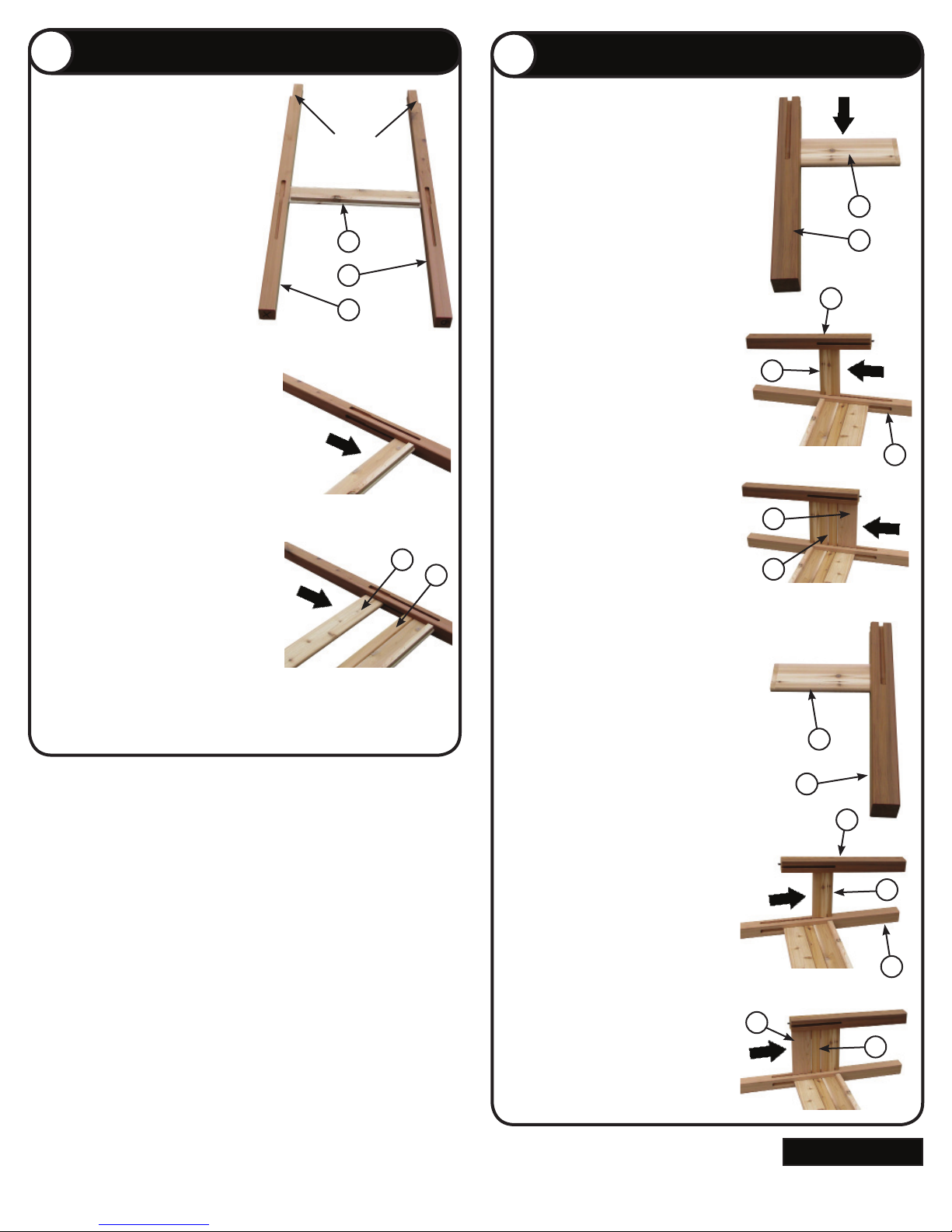
Locate one 4” x 4” x 80” corner post
(Item 21) marked with an “X” and one
4” x 4” x 80” corner post (Item 22)
marked with an “O”.
Place the two posts fl at on the ground
with slots facing up and slots facing
the inside. Ensure that the notches
face outward.
Locate and install one 31” x 5-1/2”
side rail w/cleat (Item 8) (with cleat
facing you) into the upper (wide) part
of the slot on the two posts.
Slide the side rail down to the bottom
of the slot.
Install one 31” x 2-1/2” narrow center
side rail (Item 7) and slide down.
Install one 31” x 5-1/2”side rail (Item
9) and slide down.
“X”
Notches
22
21
Locate one 4” x 4” x 32” corner post
(Item 11) and one 14-1/2” x 5-1/2”side
rail (Item 5).
Place the post on the ground (slots
towards the top), turn the post until one
slot is facing you and a second slot is
facing to the right. Slide the side rail into
“O”
slot and slide to the bottom of the slot.
Rotate the 4” x 4” x 32” corner post
11
11
(Item 11) and the 14-1/2”x 5-1/2” side
rail (Item 5) 90°, install the side rail into
the upper (wide) part of the slot on the
4” x 4” x 80” corner post (Item 21) and
slide to the bottom of the slot.
21
Install one 14-1/2” x 2-1/2” narrow
center side rail (Item 3) and slide down.
Install one 14-1/2” x 5-1/2” side rail
(Item 5) and slide down.
Locate one 4” x 4” x 32” corner post
(Item 11) and one 14-1/2”x 5-1/2” side
rail (Item 5).
Place the post on the ground (slots
towards the top), turn the post until one
slot is facing you and a second slot is
facing to the left. Slide side rail into slot
and slide to the bottom of the slot.
Rotate the 4” x 4” x 32” corner post
(Item 11) and the 14-1/2” x 5-1/2” side
rail (Item 5) 90°, install the side rail into
the upper (wide) part of the slot on the
4” x 4” x 80” corner post (Item 22) and
slide down to the bottom of the slot.
Install one 14-1/2” x 2-1/2” narrow
center side rail (Item 3) and slide down.
Install one 14-1/2” x 5-1/2” side rail
(Item 5) and slide down.
11
11
22
Continued
www.gronomics.com East Bethel, MN USA 763-753-7374
Page 4
6
Side Rail Assembly
8
7 10
7
13
12
18
18
15
6
Truss Assembly
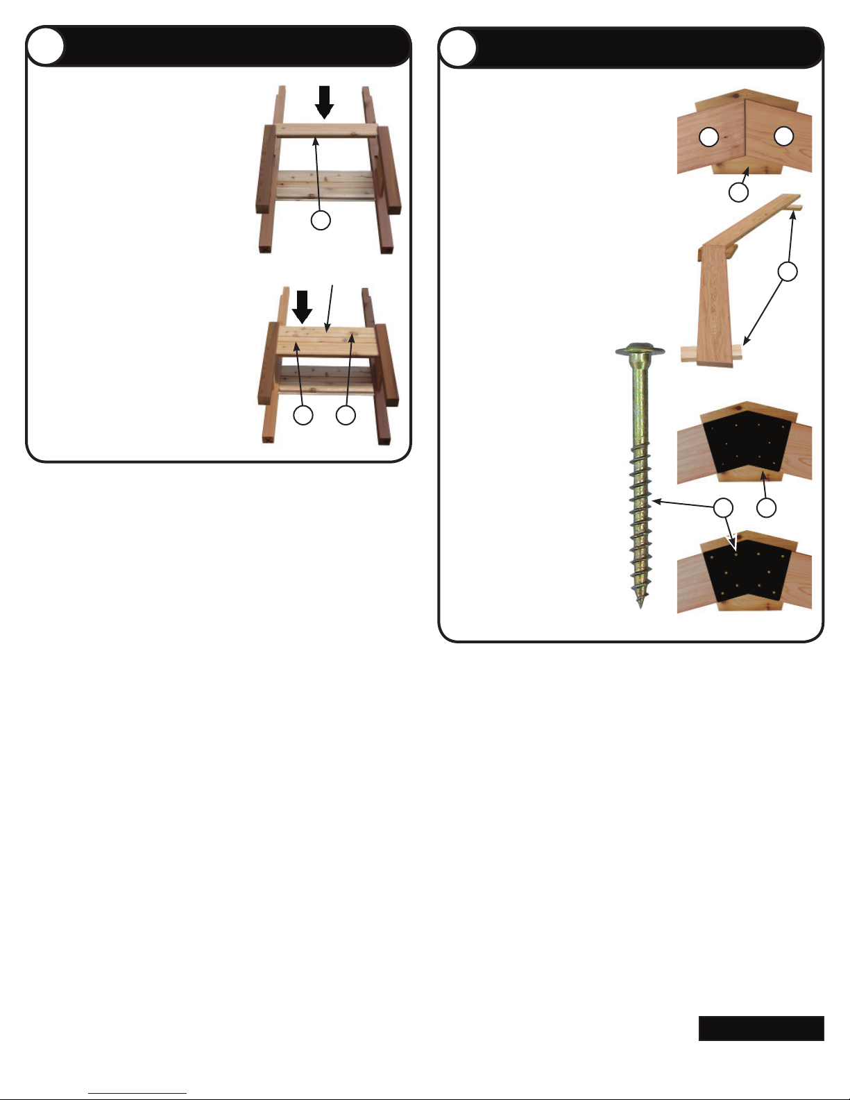
Locate and install one 31” x 5-1/2” side
rail w/cleat (Item 8) (cleat facing down)
into the upper (wide) part of the slot on
the two posts and slide down to the bottom of the slot.
Install one 31” x 2-1/2” narrow center side
rail (Item 7) and slide down and one 31” x
5-1/2” side rail w/Logo (Item 10) and slide
down.
Repeat step 4 - 6 for the second planter
box.
Logo
on top
10
Locate two 2” x 8” x 61-3/4” trusses (Item
18), one pentagon cap (Item 13) and one
support plate (Item 12). Place the
pentagon cap on the ground (face down).
Place the two trusses on the pentagon cap.
Adjust the trusses until centered left / right
and up / down on the pentagon cap. Place
one bottom board (Item 6) under each
truss. This will help level the trusses.
Place a support plate (Item 12)
onto the top of the two trusses.
Align the support plate with the
top and bottom of each truss.
Verify that the two trusses
are still contacting each other
under the support plate.
Install ten 5/16 x 2-3/4” screws
(Item 15).
18
15
13
12
18
Repeat procedure for second
truss assembly.
Continued
www.gronomics.com East Bethel, MN USA 763-753-7374
Page 5
16
16
6
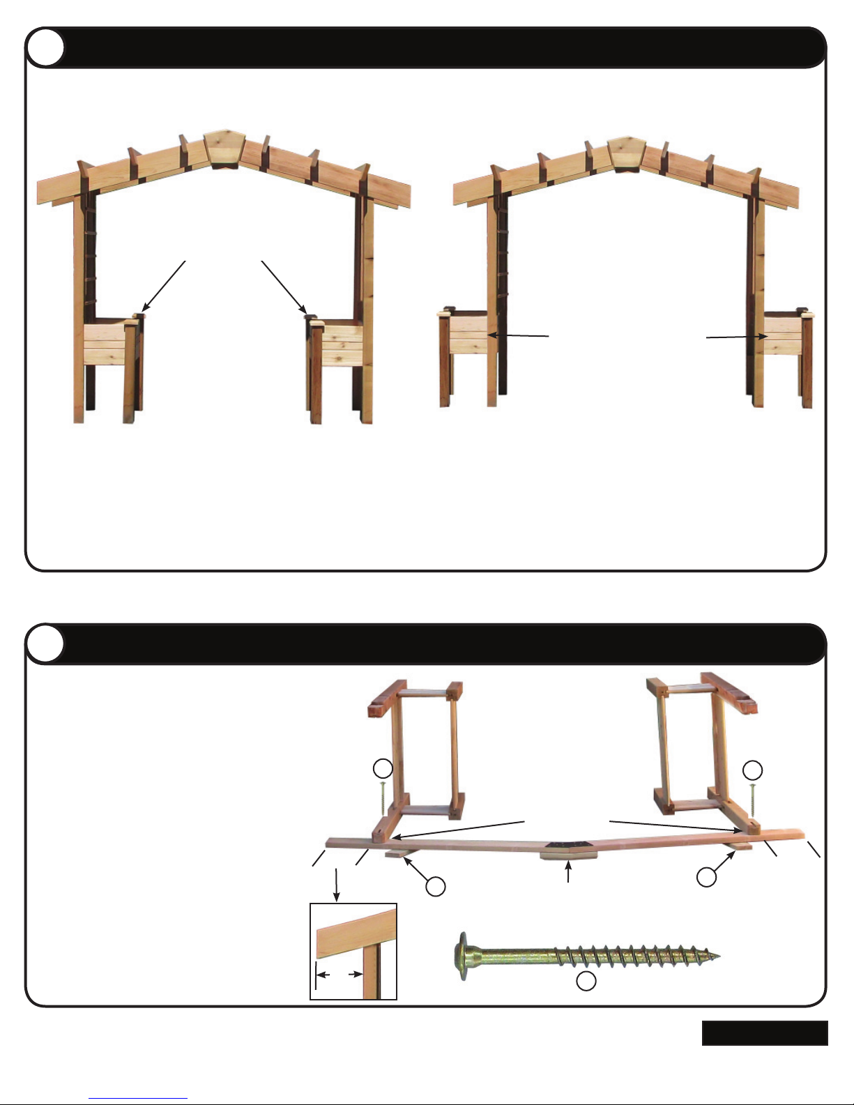
Planter Box Assembly Option
Assembled Pergola Planter with planter boxes facing in.
Assembled Pergola Planter with planter boxes facing out.
9
8
6
16
Assembled Pergola Planter with planter boxes facing in.
Planter Boxes Facing In
NOTE: The pergola planter boxes can be assembled
with the planter boxes facing in. If assembling the
planter boxes facing in, see steps 9 & 10.
Assembled Pergola Planter with planter boxes facing out.
Planter Boxes Facing Out
NOTE: The pergola planter boxes can be assembled
with the planter boxes facing out. If assembling the
planter boxes facing out, see steps 11 & 12.
Planter Box Installation (Facing In)
Place one truss assembly on the ground (pentagon
cap facing down).
Place one of the bottom boards (Item 6) under
each truss. This will help level the trusses. Place the
planter box assemblies onto the truss assembly (as
shown).
Verify that the truss assembly is contacting the
angled notch on both 80” posts.
The outside of the 4” x 4” x 80” post should be
approximately 11” from the end of the truss assembly.
Install two 5/16 x 2-3/4” (Item 16) screws through the
pre-drilled holes in the 80” posts and into the truss
assembly.
11”
11”
16
16
Angled Notch
11”
Pentagon Cap Facing Down
16
Continued
www.gronomics.com East Bethel, MN USA 763-753-7374
Page 6
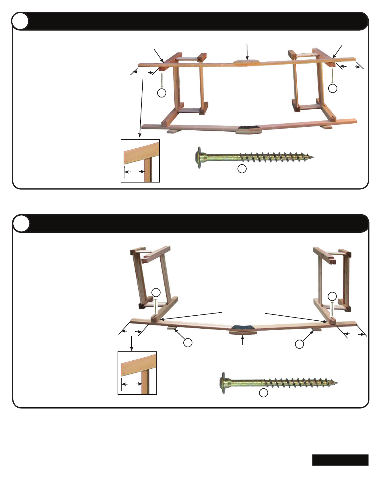
Planter Box Installation (Facing In) Continued
16
16
10
16
11
16
6
6
16
16
10
Place the second truss assembly on the top
of the planter box assemblies (pentagon cap
facing up).
Position the outside of the corner posts
approximately 11” from the end of the truss
assembly.
Verify that the truss assembly is contacting
the angled notch on both 80” posts.
Install two 5/16 x 2-3/4” (Item 16) screws
through the slot in the 80” post and into the
truss assembly.
Angled Notch
11”
11”
16
Pentagon Cap Facing Up
16
Angled Notch
11”
16
Planter Box Installation (Facing Out)
11
Place one truss assembly on the ground
(pentagon cap facing down).
Place one of the bottom boards (Item 6)
under each truss. This will help level the
trusses. Place the planter box assemblies
onto the truss assembly (as shown).
Verify that the truss assembly is contacting
the angled notch on both 80” posts.
The outside of the 4” x 4” x 80” post should
be approximately 18” from the end of the
truss assembly.
Install two 5/16 x 2-3/4” (Item 16) screws
through the pre-drilled holes in the 80” posts
and into the truss assembly.
18”
18”
16
16
Angled Notch
18”
Pentagon Cap Facing Down
16
Continued
www.gronomics.com East Bethel, MN USA 763-753-7374
Page 7
12
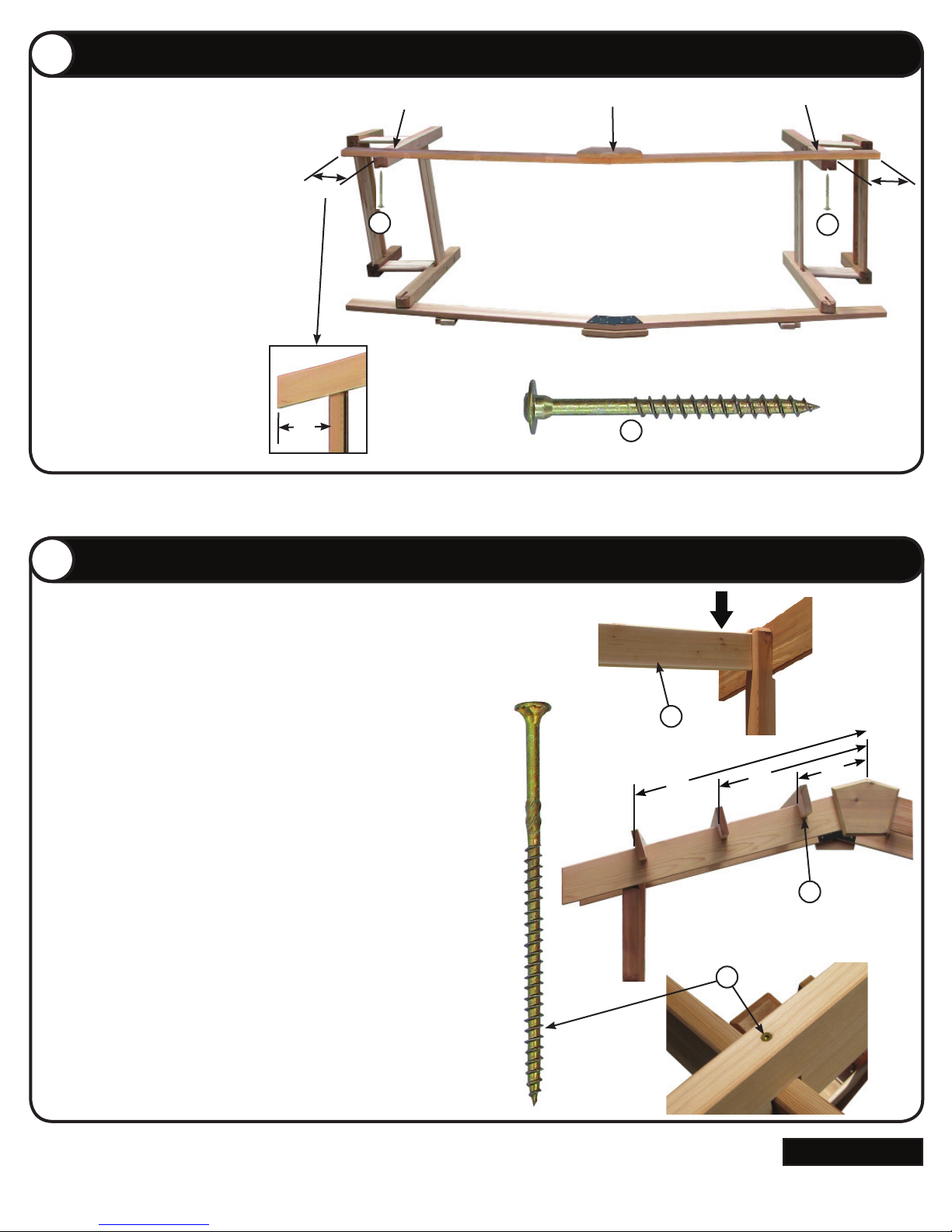
Planter Box Installation (Facing Out) Continued
16
16
16
13
9
17
19
12
Place the second truss assembly on the top
of the planter box assemblies (pentagon cap
facing up).
Position the outside of the 80” corner posts
approximately 18” from the end of the truss
assembly.
Verify that the truss assembly is contacting
the angled notch on both 80” posts.
Install two 5/16 x 2-3/4” (Item 16) screws
through the slot in the 80” post and into the
truss assembly.
18”
18”
Angled Notch
16
Pentagon Cap Facing Up
16
Angled Notch
16
18”
Securing Truss Assembly
13
Stand pergola up. Locate one 31” x 5-1/2” side rail (Item 9). Install the side
rail into the slot on the two 80” posts, securely fastening the two posts
together.
Repeat on opposite side.
Locate the six 2” x 6” x 60” truss cross pieces (Item 19). Place one truss
cross piece (notch down) onto the truss assemblies 16” from the middle
of the truss assembly. Slide down until it contacts the 80” posts. Install the
next truss cross piece 32” from the middle of the truss assemblies. Install
the next truss cross piece 48” from the end of the truss assemblies.
Fasten each truss cross piece in place with one 10 x 4” deck screw (Item
17) (both sides). When installing the deck screws, tighten the screw unit it
makes contact with the truss cross piece.
NOTE: If the screw is installed too deep, it may allow moisture to penetrate
the wood and may cause damage to the structure.
48”
17
32”
19
16”
Repeat procedure for opposite side of truss assemblies.
Continued
www.gronomics.com East Bethel, MN USA 763-753-7374
Page 8
14
14
2
15
4
6
16
20
14
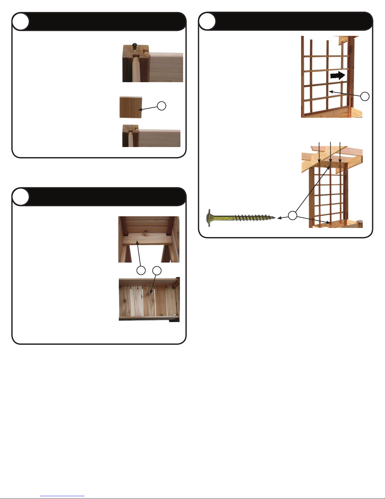
Cap Assembly
Trellis Assembly
16
Remove the rubber cap from the corner
posts studs of the planter boxes.
Align the hole of the 4” x 4” post cap (Item
2) with stud and tighten until the cap
makes contact with the post.
Planter Box Final Assembly
15
Locate two 15-1/2” x 4-1/2” corner notched
bottom boards (Item 4). Place the two
boards on each end of the planter box.
Locate the 29” x 52” trellis assemblies
(Item 20). Extend one trellis assembly.
Place the trellis assembly onto the top of
the planter box and slide over until all the
boards contact the 80” post. This will help
square up the trellis before installing.
20
Align the the top of the trellis on the
center of the top side rail, center the
trellis left and right and fasten with six 8 x
1-1/2” screws (Item 14) on top & bottom
of trellis.
Repeat this procedure on other side.
Align top of trellis on
center of side rail
14
Repeat for second planter box.
Locate four 15-1/2” x 5-1/2” bottom boards
(Item 6). Install into the bottom of planter
box.
Repeat for second planter box.
Locate the two pieces of fabric liner (Item
1). Place one piece in the bottom of each
planter box.
Soil Capacity: 6 Cubic Feet
Product Care & Maintenance
Western Red Cedar will turn a weathered grey if left
unfinished. Although no finish is required for
cedar products when used outdoors, a natural oil finish
applied regularly will help maintain the beauty and
minimize cracking and drying. It is
recommended to use Gronomics Garden Bed Oil
(Item # GBO-1Q), a non-toxic, food safe finish that is
very easy to apply.
www.gronomics.com East Bethel, MN USA 763-753-7374
 Loading...