

Page 1
INSTALLATION
MANUAL
www.gromaudio.com
www.gromaudio.com/support.html
NISK
Page 2

CONTENTS
Package contents......................................................................................................3
CHAPTER 1 — INSTALLATION. ................................................................................3
1.1 Before Installation 3
1.2 Tools 3
1.3 Vehicle Installation 3
1.4 Safety Guidelines & Appropriate Use 4
Connect VLine Interface Cable to factory headunit . ...........................................5
Display connections . . .............................................................................................6
Connecting to VLine..................................................................................................6
Routing the GPS Antenna. . . ....................................................................................7
Routing the Microphone. . .......................................................................................8
Mounting the VLine Module. . .................................................................................9
Understanding VLine Ports. ..................................................................................10
Chapter 2 — getting started. . ...............................................................................11
2.1 Initializing
2.2 Functions
SUPPORT. ........................................................................................................13
WARRANTY......................................................................................................13
18 MONTH (18) LIMITED WARRANTY
GRANT OF LICENSE........................................................................................14
OPERATIONAL WARNING AND SAFETY INSTRUCTIONS. ...........................15
Page 3
3
1.1 Before Installation
Before starting work with any wiring, please wait 90 seconds after turning the
Ignition to the OFF position and disconnecting the negative (-) terminal of the
battery. This is to ensure that no SRS airbags faults are triggered during the
installation when disassembling the vehicles panels and wiring connections
for the VLINE module installation.
Please review the entire manual to familiarize yourself of the VLINE module
and the installation requirements before installing the unit and using it.
1.2 Tools
Have Tools ready for disassembling the dashboard panels to remove the
stereo.
Some basic tools will be required for stereo removal and installation: plastic
prying tools, Phillips head screwdriver,10mm socket and ratchet. Additional
tools may be required depending on vehicle and installation preference.
1.3 Vehicle Installation
Each model vehicle disassembles differently. The removal of the stereo and
CHAPTER 1 — INSTALLATION
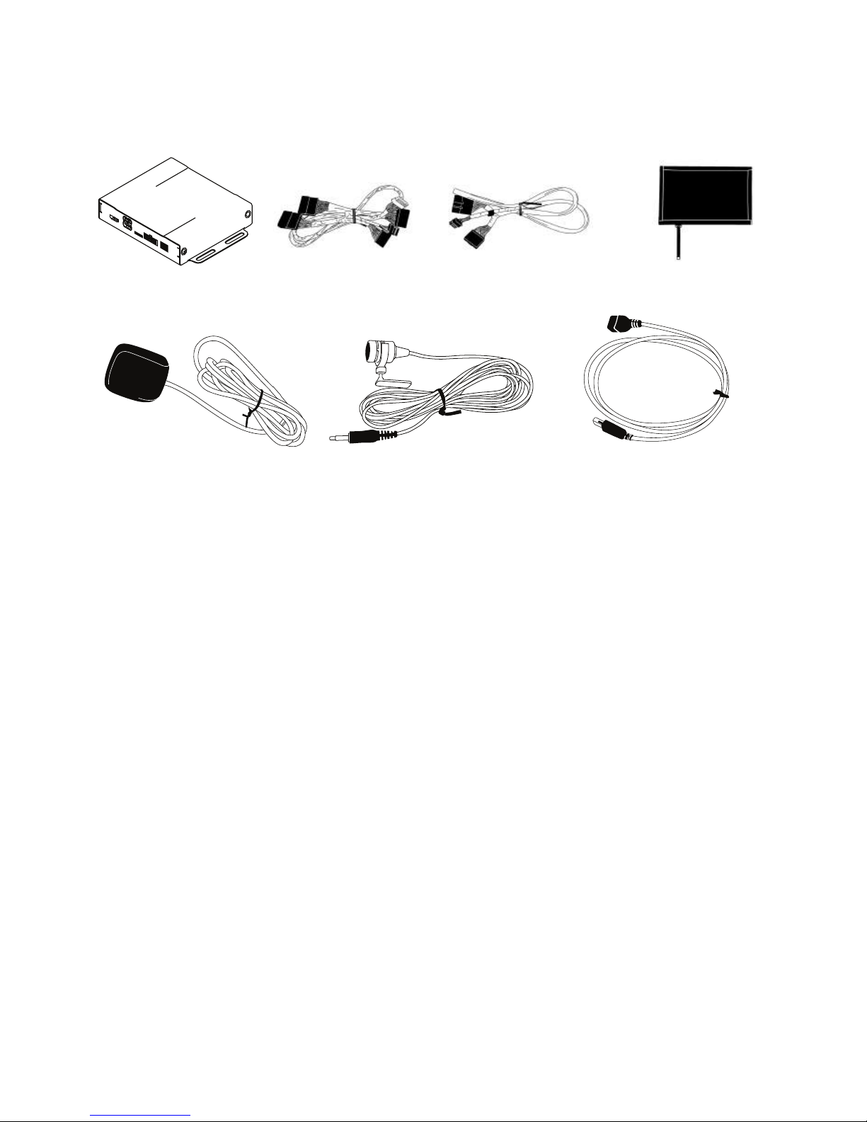
PACKAGE CONTENTS
GROM-VLINE SYSTEM
Microphone USB Extension cable
VLine module
GPS Antenna
MCFNISK Interface Cable VNISK Video Cable
V-NISKRTH Touch
Screen Assembly
Page 4

wiring requires special technical skills and experience. If you do not feel
comfortable doing the installation, please consult with your local car audio
shop or installation professional for instructions or assistance, if necessary.
Carefully remove the factory stereo and display out of the dash cavity with
proper tools.
It may be necessary to disconnect items surrounding the stereo and display
to remove them and gain access to the back of the stereo to make your
connections. Make sure to reconnect them back during the reassembly.
1.4 Safety Guidelines & Appropriate Use
By using VLine you agree:
• to operate VLine only when there are safe driving conditions;
• to follow any applicable state and traffic laws;
• to keep an eye on the road at all time while driving;
• do not attempt to play video (such as YouTube) on a display while the
vehicle is in motion;
• do not use VLine without running the engine for the extended period of
time as it can drain the battery.
Do not use Vline in a manner that would distract the driver or that may
otherwise cause injury or death to vehicle occupants or bystanders.
IT IS ILLEGAL IN MOST STATES OF THE UNITED STATES AND MAY BE ILLEGAL
IN OTHER JURISDICTIONS FOR ANY TELEVISION OR OTHER VIDEO DISPLAY,
STREAM, TRANSMISSION OR BROADCAST TO BE VISIBLE TO THE DRIVER
WHILE THE VEHICLE IS IN MOTION. YOU AGREE NOT TO USE ANY VISUAL
COMPONENT OF VLine WHILE IN CONTROL OF A MOVING VEHICLE WHERE
DOING SO WOULD BE ILLEGAL OR DANGEROUS TO VEHICLE OCCUPANTS OR
BYSTANDERS. DOING OTHERWISE CAN LEAD TO SERIOUS INJURY OR DEATH
TO YOU AND OTHERS. PLEASE FIND A SAFE PLACE TO PARK AND ENGAGE
THE PARKING BRAKE BEFORE VIEWING ANY VIDEO DISPLAYS, STREAMS,
TRANSMISSION, OR BROADCAST AVAILABLE THROUGH VLINE.
4
Page 5
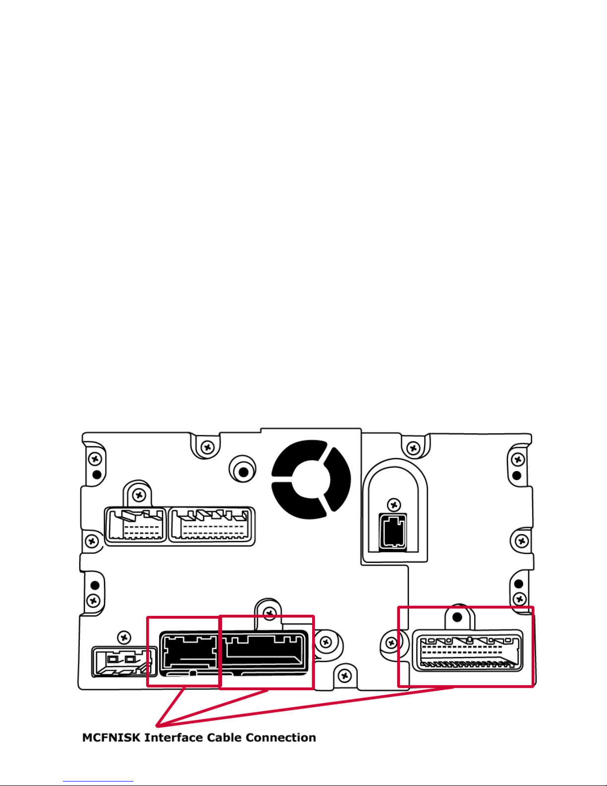
Step 2 - Connect VLine interface cable to factory headunit
Locate the 18-pin and 32-pin connectors behind the stereo headunit and
unplug them. Plug in supplied interface cable (MCFNISK). Reconnect back
what was disconnected from the rear of the stereo into the female plugs of
the supplied MCFNISK interface cable.
Locate the 12-pin port behind the stereo headunit. If there is already
connector plugged in, unplug it and plug MCFNISK 12-pin connector
instead. Leave what was unplugged from the rear of the stereo free and
disconnected. It will not be used.
*Please note that the factory XM/SAT will be disabled and no longer
function. The VLINE will take its place and emulate its functions.
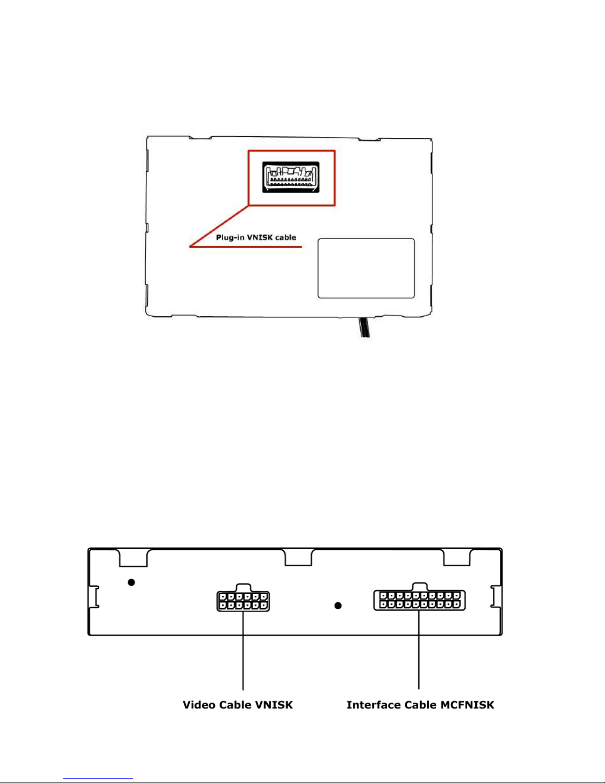
Step 1 - Install stereo touchscreen overlay
Take out the stereo screen and disconnect it from the 24-pin factory connector. Mark this connector for yourself as you will need to replug it back to VLine
video cable.
Take the screen assembly to the comfortable place where you can install the
touchscreen overlay. We recommend using a table. Refer to the manual that
came with your touchscreen overlay package (V-NISKRTH).
Page 6
6
Step 3 - Connect VLine video cable to factory display
Take stereo display with already installed touchscreen overlay (step 1).
Locate 24-pin port at the rear of the display and plug in the supplied video
cable (VNISK). Reconnect factory 24-pin connector back to VNISK female
plug of the supplied interface cable.
Step 4 - Connecting to VLine
Connect the MCFNISK and VNISK cables to the appropriate ports of VLine
module You will connect V-TOUCH display cable, with TSB1 board attached,
to the connector labeled “TOUCH” on the VAUX cable of GPS antenna
assembly (see next page).
Carefully route all VLine cables (VNISK, MCFNISK, V-TOUCH) to the glove
compartment, where you will connect them to VLine. Be extra carefull with VTOUCH cable!
Page 7

7
Step 5 - Routing the GPS Antenna
The GPS antenna package consists of the antenna connected to VAUX
cable. It also comes with the double-sided tape.
It can be mounted on the top of the dashboard or outside of the vehicle.
We recommend mounting it inside of the vehicle on the passenger side,
on top of the dashboard (see below). Do not leave GPS antenna inside of
the glove compartment, as it can affect the reception of GPS signal.
Plug the VAUX cable into the port labeled CAMERA AV1 on the VLine.
Plug the V-TOUCH cable, with TSB1 board attached, to the connector
labeled “TOUCH” on the VAUX cable with GPS antenna.
Page 8

Step 6 - Routing the Microphone
Route the microphone to a location where it will be able to pick up voice
clearly. We recommend to mount MIC nearby the rear view mirror but not
directly
on windshield glass. Avoid sticking to a hard surface as it will pick up more
noise.
Plug the microphone into the MIC port of the VLine module
8
Page 9

9
Step 7 - Mounting the VLine Module
Mount the module in a location free of any moving parts. We strongly recommend mounting the module in an easily accessible location such as the
glove compartment . It will provide easy access to the USB ports of VLine.
Securely mount and install VLine module in a location free from heat,
humidity, moving parts, or direct sunlight. Beware of hot-air flow from your
vehicle’s climate control system. The module should be secured in a suitable
location, free of sharp metal edges, using double-sided tape, Velcro, or wire
ties. The module’s operating temperature range is -30°C to +70°C (-24°F to
+158°F)
Page 10

10
USB1
iPhone connection
Any other USB device (Keyboard / Mouse)
USB2
USB flash drive
Any USB device (Android, Keyboard / Mouse)
MicroSD
Insert microSD card (*pin side up) to increase storage space for
Vline (up to 128GB supported). The microSD should be formatted
FAT32. File system format exFAT and NTFS are not supported.
HDMI IN
HDMI input connection to connect external video sources.
(add plugin to Dashlinq Launcher to use feature)
HDMI OUT
N/A, not used
MIC
Microphone input, Connect 3.5mm Mono Microphone
Understanding VLine Ports
HDMI IN
HDMI Input MicroSD Card
(Pin side up*)
Pin Side Up
N/A
Not Used
GPS / AV / Camera
Input
WiFi / Bluetooth
Antenna
Microphone
USB2
OTG/USB storage
MIC
CAMERA AV1
HDMI OUT
USB 2
USB 1
USB1
iPhone
Page 11

11
2.2 Initializing
After connecting the VLine module to the stereo and disconnecting the
XM/SAT tuner, an ignition cycle will have to be performed for the stereo to
discover Vline and allow Vline to self configure.
To INITIALIZE:
1. Put Ignition Switch to “ACC” or “ON” position
2. Wait up to 5 Seconds
3. Put Ignition Switch to “OFF” position
4. Wait 1 minute
5. Turn Ignition Switch back to “ACC” or “ON” Position
6. Press RADIO button until you are in XM Mode. NISK VLine model emu-
lates XM/SAT mode of your vehicle.
CHAPTER 2 — GETTING STARTED
2.1 Disconnect XM/SAT Tuner
Locate and disconnect XM tuner in your vehicle. Possible locations include:
under rear deck, under left or right trunk floor. The location of XM tuner in
your vehicle might be different, so please refer to your vehicle’s
documentation or contact us for help.
VLine will not work if you do not disconnect XM/SAT tuner in your
vehicle!
Page 12

12
User Manual
Please refer to the User Manual included with your purchase regarding to
the next steps required to set up your VLine Infotainment System.
2.3 Functions
No factory functions, except XM/SAT Radio, of the stereo will be
disabled. Factory Bluetooth, AM/FM Radio and CD player will remain
functional.
2.3.1 Selecting the VLINE mode:
Press the RADIO button until you are in XM/SAT mode of the stereo to enter
into VLINE interface mode.
For stereos with SAT button, press SAT button to activate VLine mode.
NOTE: Please note factory XM/SAT function is disabled when installing VLine.
2.3.2 Button Controls of the VLine Mode
Track selection can be done with the stereo’s Seek Track ^ and v buttons.
2.3.3 Programming Steering Wheel Control Buttons
You will need to program steering wheel controls if your stereo has [PRESET
AB-C] button:
1. Press [PRESET A-B-C] button until you are in preset C.
2. Press [RADIO] button until the stereo is in VLine mode.
3. Press and hold buttons/presets 1-6 one at a time until you hear a beep
sound.
If your stereo does not have [PRESET A-B-C] button, you do not need to
program steering wheel control buttons.
Page 13

13
TROUBLESHOOTING
Stereo is not “seeing” VLine, or there is interference with XM/SAT - what
can I do?
Make sure to locate and disconnect XM/SAT tuner installed in your vehicle.
I can’t get GPS signal - what can I do?
Make sure GPS antenna is installed in the location that is free from
obstacles or metal parts. We recommend installing on top of the dashboard, on the passenger side of the vehicle.
WARRANTY
Eighteen (18) Month Limited Warranty
This warranty covers any supplied or manufactured parts of the product
that, upon inspection by GROM Audio authorized personnel, is found to have
failed in normal use due to defects in the material or workmanship. This
warranty does not apply to the installation expenses. Attempting to service
or modify this unit, operating this unit under conditions other than the
recommended will render this warranty void.
Unless otherwise prescribed by law, GROM Audio shall not be liable for any
personal injury, property damage and or any incidental or consequential
damages of any kind (including water damage) resulting from malfunctions,
defects, misuse, improper installation or alteration of this product.
All parts of this product are guaranteed for a period of 18 month as follows:
Within the first 18 months from the date of purchase, subject to the
conditions above, GROM Audio will repair or replace the product at their
discretion, if it is defective in the material or workmanship.
SUPPORT
Technical support: http://gromaudio.com/support.html
Live chat: https://gromaudio.com
FAQ: www.gromaudio.com/support/faq.html
VLine Setup & Use Videos:
http://gromaudio.com/vline/ video.html
VLine installs:
https://gromaudio.com/installs/index.html
Page 14

14
BETWEEN YOU, AS “THE END USER”, AND GROM Audio (“GROM”). PLEASE
CAREFULLY READ THE TERMS AND CONDITIONS OF THIS AGREEMENT
BEFORE USING THE GROM PRODUCTS. BY USING THE GROM PRODUCT
AND THE SOFTWARE INSTALLED ON THE GROM PRODUCT, YOU ARE
AGREEING TO BE BOUND BY THE TERMS OF AGREEMENT. SINCE GROM
DOES NOT INSTALL THIS EQUIPMENT, GROM DISCLAIMS ANY LIABILITY FOR
IMPROPER INSTALLATION OF THE GROM PRODUCT. FURTHER, THE END
USER ACKNOWLEDGES THAT THE PRODUCT AND ITS SOFTWARE ARE NOT
INHERENTLY DANGEROUS AND DO NOT PROVIDE ANY INHERENT RISKS
AND THEREFORE POTENTIAL DAMAGES TO THE END-USER, OTHER THAN
‘Fitness for its Purpose’. As manufacturers continuously develop and modify
stereo receiver models, they may cause you to experience some technical
difficulties. If the product does not operate properly, please contact technical
department promptly at www.gromaudio.com/support.html
GRANT OF LICENSE
GROM grants to you a non-transferable, non-exclusive license to use the
GROM PRODUCT and its software installed on the GROM PRODUCT (the
“SOFTWARE”) and the related documentation solely for your own personal
use or for internal use by your business, only on such GROM PRODUCTS.
You shall not copy, reverse engineer, translate, port, modify or make derivat-
ive works of the Software contained in the PRODUCT. You shall
not loan, rent, disclose, publish, sell, assign, lease, sublicense, market or
LEGAL AGREEMENT and SAFETY DISCLAIMER
GROM AUDIO VLINE Infotainment Upgrade System (hereinafter referred to
as ‘GROM PRODUCT’) and its related software. THIS IS A LEGAL AGREEMENT
All customers should contact GROM Audio support team at http://
gromaudio. com/support.html and obtain an RMA number and Return
Instructions. All defective product returned to GROM Audio within
warranty period must
be accompanied by the original invoice (or copy). All shipping handling
charges are non-refundable. Warranty does not cover normal tear and
wear, damages due to negligence, improper installation, and operation.
WITHOUT RMA NUMBER THE RETURNS ARE NOT ACCEPTED!
Page 15

15
otherwise transfer the Software in the PRODUCT or use it in any manner not
expressly authorized by this agreement. You shall not derive or attempt to
derive the source code or structure of all or any portion of the Software in the
PRODUCT by reverse engineering, disassembly, recompilation, or any other
means. You shall not use the Software in the PRODUCT to operate a service
bureau or for any other use involving the processing of data for other persons
or entities. GROM and its licensor(s) shall retain all copyright, trade secret,
patent and other proprietary ownership rights to the Software in the
PRODUCT. You may transfer all of your license rights in the Software or the
PRODUCT, the related documentation and a copy of this License Agreement
And Warranty to another party, provided that the party reads and agrees to
accept the terms and conditions of this License Agreement And Warranty.
OPERATIONAL WARNING AND SAFETY INSTRUCTIONS
(A) EXCEPT AS OTHERWISE CONTAINED HEREIN, the PRODUCTS and related
documentation are provided to you, “AS IS”. IN NO EVENT SHALL GROM BE
LIABLE FOR ANY DAMAGES, CLAIM OR LOSS INCURRED BY YOU (INCLUDING
WITHOUT LIMITATION, COMPENSATORY, INCIDENTAL, INDIRECT, SPECIAL,
CONSEQUENTIAL, OR EXEMPLARY DAMAGES, LOST PROFITS, LOST
SALES OR BUSINESS EXPENDITURES, INVESTMENTS, OR COMMITMENTS
IN CONNECTION WITH ANY BUSINESS, LOSS OF ANY GOODWILL, OR DAMAGES. THE TERM ‘INCIDENTAL DAMAGES’ REFERS TO THE EXPENSES
OF TRANSPORTING THE PRODUCTS TO THE GROM AUDIO SERVICE CENTER,
LOSS OF THE END-USERS [ORIGINAL PURCHASER’S] TIME, LOSS OF THE USE
OF THE PRODUCT, BUS FARES, CAR RENTALS OR OTHER COSTS RELATED TO
THE CARE AND CUSTODY OF THE PRODUCT. THE TERM ‘CONSEQUENTIAL
DAMAGES’ REFERS TO THE COST OF REPAIRING OR REPLACING OTHER
PROPERTY, WHICH IS DAMAGED WHEN THIS PRODUCT DOES NOT WORK
PROPERLY, RESULTING FROM THE USE OR INABILITY TO USE THE PRODUCTS,
INCLUDING ANY DAMAGES INCURRED DUE TO THE NEGLIGENT OPERATION
OF A MOTOR VEHICLE, IN CONJUNCTION WITH THE USE OF SAID PRODUCTS.
THE END USER ACKNOWLEDGES ITS RESPONSIBILITY FOR THE USE OF
THE PRODUCT. THE ADDITION OF GROM PRODUCTS AND ANY AFTERMARKET
EQUIPMENT MAY ENHANCE THE VALUE OF A VEHICLE OR CAUSE
A THIRD-PARTY TO ILLEGALLY ATTEMPT TO REMOVE THE PRODUCTS AND
AFTER-MARKET EQUIPMENT. GROM DISCLAIMS ANY LIABILITY RELATED
TO SUCH THEFT AND POTENTIAL DAMAGE TO PROPERTY. IT IS THE ENDUSERS RESPONSIBILITY TO PROTECT ITS OWN PROPERTY. THE END-USER
FURTHER ACKNOWLEDGES THAT THE OPERATION OF A MOTOR VEHICLE
IS AN INHERENTLY DANGEROUS ACTIVITY, AND BY ITS USE OF GROM’S
PRODUCTS, ACKNOWLEDGES THAT THE PRODUCTS ARE REMOTELY
Page 16

RELATED TO SAID MOTOR VEHICLE OPERATION, AND THUS ANY DAMAGES
CAUSED TO THE DRIVER OF THE VEHICLE, THE VEHICLE ITSELF OR ANY
THIRD-PARTY AND ITS PROPERTY IS NOT THE RESPONSIBILITY OF GROM, ITS
AGENTS OR ITS PRINCIPALS AND IS THE SOLE RESPONSIBILITY OF THE
DRIVER OF SAID VEHICLE.
YOU, THE END-USER, OR ANY OTHER DRIVER OF THE VEHICLE, IS SOLELY
RESPONSIBLE FOR THE SAFE OPERATION OF THE VEHICLE AND THE SAFETY
OF BOTH YOU AND THE PASSENGERS. FOR SAFETY PURPOSES, THE
PRODUCT SHOULD NOT BE USED FOR THE DRIVER’S ENTERTAINMENT,
WHILE THE VEHICLE IS BEING DRIVEN. SUCH USE COULD BE A DISTRACTION
TO THE DRIVER, WHICH COULD CAUSE AN ACCIDENT LEADING TO SERIOUS
INJURY OR DEATH. IF YOU, THE END-USER ALLOW ANOTHER PERSON TO USE
THE VEHICLE, IT IS YOUR RESPONSIBILITY TO THOROUGHLY BRIEF THAT
OTHER USER, ON THE SAFETY REQUIREMENTS FOR OPERATING THE VEHICLE
AND THE PRODUCTS INSTALLED THEREIN.
(B) SAID DISCLAIMERS SHALL APPLY TO THE USE OF SAID PRODUCTS, EVEN
IF GROM HAS BEEN INFORMED OF, KNEW OF, OR SHOULD HAVE KNOWN
OF THE LIKELIHOOD OF SUCH DAMAGES. THIS LIMITATION APPLIES TO ALL
CAUSES OF ACTION IN THE AGGREGATE, INCLUDING WITHOUT LIMITATION:
BREACH OF CONTRACT, BREACH OF WARRANTY, NEGLIGENCE, STRICT
LIABILITY, MISREPRESENTATION AND OTHER TORTS. IF GROM’S WARRANTY
DISCLAIMER OR LIMITATION OF LIABILITY SET FORTH IN THIS AGREEMENT
SHALL, OR FOR ANY REASON WHATSOEVER, BE HELD UNENFORCEABLE
OR INAPPLICABLE, YOU AND ANY OTHER END USER AGREE THAT GROM’S
LIABILITY SHALL NOT EXCEED (70%) OF THE PRICE PAID FOR THE ENCLOSED
GROM PRODUCT.
Some states do not allow the exclusion or limitation of incidental or
consequential damages, so the above limitation or exclusion may not apply
to you. This Warranty Disclaimer and Limitation of Liability shall not be applicable to the extent that any federal, state, or local law, which cannot be
preempted, prohibits any provision of this Warranty.
Any use of the PRODUCTS where it is illegal to do so, may be used against
you as evidence of negligence in the event of an auto accident or other traffic
infraction.
By purchasing or otherwise obtaining GROM Product you agree:
- to operate GROM Products only when there are safe driving conditions;
16
Page 17

17
- to follow any applicable state and traffic laws;
- to keep an eye on the road at all time while driving;
- do not attempt to play video (such as YouTube) on a display while
the vehicle is in motion;
- do not use GROM Product without running the engine for the extended period of time as it can drain the battery.
You futher agree to use the GROM Product in:
- a manner consistent with all applicable laws and regulations
and this Agreement;
- a reasonable, safe and appropriate manner considering all the
circumstances associated with that use.
You agree not to use the GROM Product:
- for any illegal, non-personal or unauthorized purpose,
- in a manner that could damage or cause risk to GROM Audio business,
reputation, employees, customers, facilities, or to any third party,
- in a manner that would distract the driver or that may otherwise cause
injury or death to vehicle occupants or bystanders.
GROM Audio is not in any way responsible for any such use by you. In all
cases, GROM Audio may limit or revoke your use for any reason and at
any time. Use of some GROM Product features while a vehicle is in motion
may be against the laws of the jurisdiction in which you use the GROM
Product. Use of some GROM Product features by the driver or by the vehicle
occupants while a vehicle is in motion may also be distracting to the driver
and could cause serious injury or death to vehicle occupants or bystanders.
IT IS ILLEGAL IN MOST STATES OF THE UNITED STATES AND MAY BE ILLEGAL
IN OTHER JURISDICTIONS FOR ANY TELEVISION OR OTHER VIDEO DISPLAY,
STREAM, TRANSMISSION OR BROADCAST TO BE VISIBLE TO THE DRIVER
WHILE THE VEHICLE IS IN MOTION. YOU AGREE NOT TO USE ANY VISUAL
COMPONENT OF GROM Product WHILE IN CONTROL OF A MOVING VEHICLE
WHERE DOING SO WOULD BE ILLEGAL OR DANGEROUS TO VEHICLE OCCUPANTS OR BYSTANDERS. DOING OTHERWISE CAN LEAD TO SERIOUS INJURY
OR DEATH TO YOU AND OTHERS. PLEASE FIND A SAFE PLACE TO PARK AND
ENGAGE THE PARKING BRAKE BEFORE VIEWING ANY VIDEO DISPLAYS,
STREAMS, TRANSMISSION, OR BROADCAST AVAILABLE THROUGH GROM
Product.
Page 18

such Third Party Materials.
Third Party Materials may have their own terms of use and/or privacy policy,
and may have different practices and requirements to those operated
by GROM AUDIO with respect to GROM Product. You are responsible for
reviewing any terms of use, privacy policy or other terms governing your
use of these Third Party Materials, which you use at your own exclusive
responsibility and risk. By using the Third Party Materials, you agree to
comply with the use terms of the provider of such Third-Party Materials.
GROM AUDIO does not warrant or endorse and does not assume and will
not have any liability or responsibility to you or any other person for any
Third Party Materials or for any other materials, products, or services of third
parties. By using the Third Party Materials, you agree to comply with the use
terms of the provider of such Third-Party Materials.
LOCATION, MAPS, NAVIGATION AND TRAFFIC DATA
Location and traffic data provided by GROM Product is for basic navigational
purposes only and is not intended to be relied upon in situations where
precise location information is needed or where erroneous, inaccurate
or incomplete location data may lead to death, personal injury, property
or environmental damage. Real world traffic restrictions, advisories and
conditions are always more important than guidance given by third party
navigation/mapping data providers. Neither GROM Audio nor any of its
content providers, guarantees the availability, accuracy, completeness,
reliability, or timeliness of traffic information, navigation, or location data
provided by the GROM Product. Always excersize the caution and common
sence when using and relying on the navigation, location, maps and traffic
data with GROM Product.
18
THIRD PARTY MATERIALS
Through GROM Product, you can access third party websites, databases,
networks, servers, information, software, programs, systems, directories,
applications, products or services (collectively, “Third Party Materials”). GROM
AUDIO is not responsible for any Third Party Materials available through the
Services. You acknowledge and agree that GROM AUDIO does not have or
maintain any control over Third Party Materials and is not responsible for
examining or evaluating the content, accuracy, completeness, timeliness,
validity, copyright compliance, legality, decency, quality or any other aspect of
Page 19

19
A. INDEMNIFICATION OF GROM AUDIO, ITS AGENTS AND EMPLOYEES. By
Purchasing, Installing and Using the Products, You, the End- User, agree
to indemnify, defend and hold harmless, GROM AUDIO, and it s Affiliates,
Directors, Officers, Agents and Employees from any Liabilities, Damage, Loss,
Claim and Expense (including reasonable Attorney’s Fees) arising out of the
installation and use of the GROM Product.
B. EXCLUSION OF REMEDIES. TO THE MAXIMUM EXTENT PERMITTED UNDER
APPLICABLE LAW, IN NO EVENT WILL GROM AUDIO OR ITS EMPLOYEES,
DIRECTORS, OFFICERS AND OTHER REPRESENTATIVES BE LIABLE TO YOU
OR ANYONE ELSE FOR ANY INDIRECT, SPECIAL, INCIDENTAL, PUNITIVE,
EXEMPLARY OR CONSEQUENTIAL DAMAGES OF ANY KIND ARISING OUT OF
OR IN ANY WAY RELATING TO THIS AGREEMENT, INCLUDING YOUR USE OF
OR INABILITY TO USE THE VLINE OR ANY CLAIM MADE BY A THIRD PARTY
(INCLUDING, WITHOUT LIMITATION, LOSS OF REVENUE, PROFITS, DATA OR
GOODWILL OR OTHER COMMERCIAL OR ECONOMIC LOSS) REGARDLESS
OF THE CAUSE OF ACTION ON WHICH THE CLAIM IS BASED, EVEN IF GROM
AUDIO HAS OR YOU HAVE BEEN ADVISED OF THE POSSIBILITY OF SUCH
DAMAGES OR CLAIM.
C. GOVERNING LAW. THIS AGREEMENT and all Purchases hereunder shall be
governed by, and construed under the laws of the State of California, without
regard to conflicts of law rules. You agree that the Courts of California shall
have exclusive jurisdiction over the Parties, for all disputes.
D. FORCE MAJEURE. GROM shall not be liable for any delay or failure in
performance caused by or resulting from acts of God, fire, flood, storms,
earthquakes, tornado, other acts of nature, any accidents, riots, wars,
government intervention, embargoes, strikes, labor difficulties, equipment
failures, or any other causes beyond the control of GROM AUDIO. Quantities
are subject to availability.
OTHER PROVISIONS
By using GROM Product you acknowledge that the maps, location,
navigation and traffic data maybe inaccurate or outdated. You agree to
hold GROM Audio harmless from any claims caused by inaccurate maps,
location, navigation and traffic data. You further agree to use maps,
location, navigation and traffic applications when it is safe to the driver,
vehicle occupants and bypassers. GROM Audio is not responsible for any
mobile data charges resulted from using GROM Product.
Page 20

maintaining competitive pricing. We continuously work to test and develop
our product, however, in some cases; our interfaces may not be compatible
with your application. Due to the wide range of electronics / anomalies
found in car stereos, compatibility and/or controls may vary. Should you
experience incompatibility issues, you may contact us via our support page.
GROM Audio also carries a standard 30 day return policy.
ENGINE/SYSTEM NOISE DISCLAIMER
Engine / system noise may occur in some installations and is not easily
predictable. Should noise occur with your system, we will take commerciallyreasonable steps to diagnose the source of the noise. Depending on the
situation, noise suppressors and filters may need to be installed in order
to correct the problem. Due to the nature of electronics, noise may not be
correctable in all cases.
IF YOU DO NOT AGREE WITH THESE TERMS AND PURCHASED DIRECTLY
FROM GROM AUDIO PLEASE RETURN THE GROM PRODUCTS IN ORIGINAL
CONDITION AND IN ORIGINAL PACKAGE WITHIN FIVE (5) BUSINESS DAYS OF
RECEIPT OF THE PRODUCTS FOR A FULL REFUND OF THE PURCHASE PRICE
OF GROM PRODUCTS (SHIPPING COSTS NON REFUNDABLE).
All trademarks or registered trademarks used in this manual are for informational purposes
only, and in no way associated with GROM Audio.
Copyright © 2018 GROM Audiorev 1.0
GROM AUDIO COMPATIBILITY DISCLAIMER
GROM Audio strives to provide you with a high-quality product while
E. ENTIRE AGREEMENT. These terms and conditions constitute the entire
and exclusive agreement between you, the End-User and GROM AUDIO,
concerning the Products, and your purchase hereunder, and supersede all
statements or other agreements, whether oral or written, between you
and GROM AUDIO. No change in this Agreement shall be effective, unless
agreed to in writing by both, you, the end-user and GROM AUDIO.
 Loading...