

Page 1

38 778
Tectron
.....1
D
Tectron
Design & Quality Engineering GROHE Germany
99.180.131/ÄM 220991/05.11
GB
D
GB
.....5
.....1
.....5
I
NL
S
DK
....17
....21
....25
....29
N
FIN
PL
UAE
....33
....37
....41
....45
GR
CZ
H
P
....49
....53
....57
....61
TR
SK
SLO
HR
....65
....69
....73
....77
BG
EST
LV
LT
....81
....85
....89
....93
RO
CN
RUS
....97
...101
...105
Page 2
A B
1
B
Bitte diese Anleitung an den Benutzer der Armatur weitergeben!
Please pass these instructions on to the end user of the fitting!
S.v.p remettre cette instruction à l'utilisateur de la robinetterie!
2 3
E
A1
D
E1
F1
A
4
F
E
A1
F2
F
E2
H
I
G
J
A2
I
Page 3

A
B
5
7
N
1.
2.
3.
O
6
L
B
A
14
K2
15
B
16
S1
L
A
8
2.
1.
P
17a
180°
2.
9
V
V1
10
Q
11
C2
C
Q1
Q
S
S1
1.
3.
Q
17b
1312
Q
II
Page 4

D
Seiten ausklappen:
Elektrische Prüfdaten
• Software-Klasse A
• Verschmutzungsgrad 2
• Bemessungs-Stoßspannung 2500 V
• Temperatur der Kugeldruckprüfung 100 °C
Betriebserlaubnis
Das Produkt darf nur unter Berücksichtigung der nationalen
Vorschriften in den aufgeführten Ländern in Betrieb
genommen werden:
- Deutschland
-Österreich
Anwendungsbereich
Diese Funkelektronik ist zum Auslösen von Spülungen durch
einen Funksender oder zusätzlich einer manuellen Betätigung.
Für die manuelle Betätigung muss eine WC-Abdeckplatte für
senkrechte Montage verwendet werden. (Nicht im Lieferumfang enthalten)
Abdeckplatten mit Glas-, Holz- oder Lederoberfläche können
nicht verwendet werden.
Für die Betätigung über Funk ist der Funksender Best.Nr.: 38 758 (siehe Ersatzteile Klappseite I) zu verwenden.
Alternativ zu dem GROHE Funksender kann das Produkt auch
mit den Funksendern der Firmen Hewi, Keuco, Lehnen,
Normbau, Pressalit, AMS, Deubad, Erlau, FRELU und FSB
verwendet werden.
Der Einbau ist nur möglich bei:
- Spülkasten A: 6l-Spülkasten mit AV1, produziert ab 06.2008
- Spülkasten B: GD2 mit AV1
siehe Klappseite I.
Sicherheitsinformationen
• Die Installation darf nur in frostsicheren Räumen
vorgenommen werden.
• Die Steuerelektronik ist ausschließlich zum Gebrauch in
geschlossenen Räumen geeignet.
• Bei beschädigter äußerer Anschlussleitung des
Transformators muss diese von einem ElektroFachinstallateur ersetzt werden, um eine Gefährdung zu
vermeiden.
• Die 230 V AC dürfen nicht in den Spülkasten geführt und
der Transformator darf nicht in dem Spülkasten montiert
werden.
• Nur Originalersatz- und Zubehörteile verwenden. Die
Benutzung von anderen Teilen führt zum Erlöschen der
Garantie und der CE-Kennzeichnung.
Technische Daten der Elektronik
• Versorgungsspannung 230 V AC
(Transformator 230 V AC/12 V AC)
• Leistungsaufnahme 4 VA
• Empfangsfrequenz 868,4 MHz
• Spülmenge 3 - 6/9 l , einstellbar
(Werkseinstellung: 6 l)
• Automatische Spülung 72 Stunden
(Werkseinstellung: aktiviert)
• Schutzart
- Armatur IP 59K
- Transformator IP 55
Die Prüfung zur elektromagnetischen Verträglichkeit
(Störaussendungsprüfung) wurde mit der
Bemessungsspannung und dem Bemessungsstrom
durchgeführt.
Zulassung und Konformität
Dieses Produkt entspricht den Anforderungen der
entsprechenden EU-Richtlinien.
Die Übereinstimmungserklärungen können unter der
folgenden Adresse angefordert werden:
GROHE Deutschland Vertriebs GmbH
Zur Porta 9
D-32457 Porta Westfalica
Installation
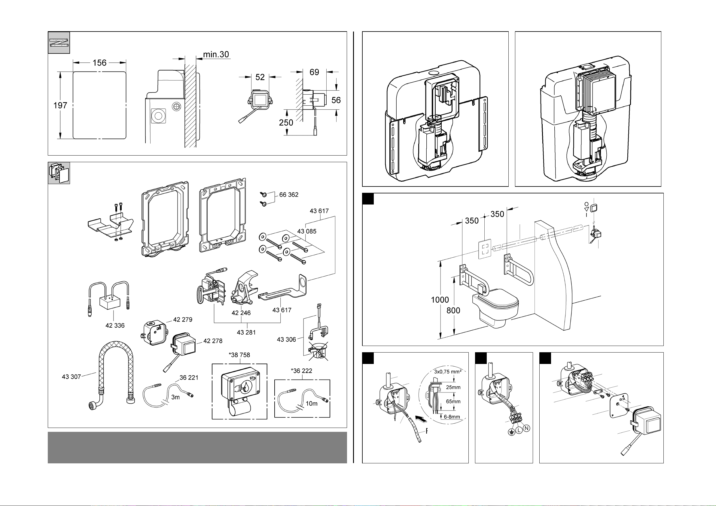
Für die Leitung zwischen Transformator (A) und Spülkasten ist
ein Leerrohr (B) mit 16mm Durchmesser erforderlich, siehe
Abb. [1].
Wand fertig verputzen und bis an Rohbauschutz verfliesen.
Elektroinstallation
Die Elektroinstallation darf nur von einem
Elektro-Fachinstallateur vorgenommen werden!
Dabei sind die Vorschriften nach
IEC 364-7-701-1984 (entspr. VDE 0100 Teil 701)
sowie alle nationalen und örtlichen Vorschriften
zu beachten!
• Es darf nur wasserbeständiges Rundkabel mit 6,0
bis 8,5mm Außendurchmesser verwendet werden.
• Die Spannungsversorgung muss separat schaltbar sein.
1. Unterteil (A1) des Transformators mit Schrauben (D)
befestigen, siehe Abb. [2].
2. 230 V-Anschlusskabel (E) in Unterteil (A1) einführen und
abisolieren.
3. Schlauch (F1) über die beiden stromführenden Adern (E1)
ziehen.
4. Lüsterklemme (F) montieren, Belegung beachten, siehe
Abb. [3].
5. Mit Kabelbinder (F2) alle drei Adern kurz vor der
Lüsterklemme (F) fixieren.
6. Kabel (E2) in einem Bogen verlegen und
Lüsterklemme (F) auf Fixierelemente im Unterteil (A1)
positionieren, siehe Abb. [4].
7. Kabel (E2) mit Schrauben (H) und Zugentlastung (G)
sichern.
8. Deckel (I) mit Schraube (J) im Unterteil (A1) befestigen.
9. Oberteil (A2) des Transformators aufstecken.
1
Page 5

Fertiginstallation
Vorbereitungen
Spülkasten A
1. Rohbauschutz (K1) vom Spülkasten nehmen, siehe
Abb. [5].
2. Verlängerungskabel (L) durch Leerrohr (B) in den
Spülkasten führen und mit Transformator (A) verbinden,
siehe Abb. [6].
3. Absperrung (N) schließen, siehe Abb. [7].
4. Vorhandenen Schlauch gegen Schlauch mit Bogen (O)
(Lieferumfang) austauschen, Absperrung (N) öffnen.
5. Zugstange (P) am Überlaufrohr befestigen, siehe Abb. [8].
6. Servomotor (V) in Halteblech (V1) einrasten, siehe
Abb. [9].
7. Rechte Lasche des Halters (Q) abtrennen, siehe Abb. [10].
8. Folie vom Klebestreifen (Q1) ziehen und Elektronikmodul (C) auf Halter (Q) befestigen, siehe Abb. [11].
Hinweis: Der Taster (C2) des Elektronikmoduls muss sich
links befinden.
9. Halter (Q) mit Schrauben (R1) und Muttern (R2) am
Rahmen (R) befestigen, siehe Abb. [12].
Hinweis: Richtigen Rahmen auswählen (durch Vergleichen
des Rahmens im Lieferumfang der Abdeckplatte).
10. Rahmen (R) aufsetzen, ausrichten und mit Scheiben und
langen Schrauben (U) am Spülkasten befestigen, siehe
Abb. [13].
Spülkasten B
1. Rohbauschutz (K2) bündig mit der Fliesenkante
abschneiden, siehe Abb. [14].
2. Verlängerungskabel (L) durch Leerrohr (B) in den
Spülkasten führen und mit Transformator (A) verbinden,
siehe Abb. [15].
3. Überlaufrohr (S1) vom Ablaufventil lösen, siehe Abb. [16].
4. a)Wasseranschluss mittig oder rechts:
Ablaufventil (S) herausziehen und um 180 ° gedreht
Rechte Lasche des Halters (Q) abtrennen.
Zugstange (P) am Überlaufrohr (S1) befestigen und
Überlaufrohr am Ablaufventil befestigen.
b)Wasseranschluss links:
Linke Lasche des Halters (Q) abtrennen, siehe
Abb. [17b].
Zugstange (P) am Überlaufrohr (S1) befestigen und
Überlaufrohr am Ablaufventil befestigen.
5. Absperrung (N) schließen, siehe Abb. [18].
6. Vorhandenen Schlauch gegen Schlauch mit Bogen (O)
(Lieferumfang) austauschen, Absperrung (N) öffnen.
7. Servomotor (V) in Halterung (V2) einrasten, siehe
Abb. [19].
8. Folie vom Klebestreifen (Q1) ziehen und
Elektronikmodul (C) auf Halte r (Q) befestigen, siehe
Abb. [20].
Hinweis: Der Taster (C2) des Elektronikmoduls muss sich
links befinden.
9. Halter (Q) mit Schrauben (R1) und Muttern (R2) am
Rahmen (R) befestigen, siehe Abb. [21].
Hinweis: Richtigen Rahmen auswählen (durch Vergleichen
des Rahmens im Lieferumfang der Abdeckplatte).
10. Rahmen (R) aufsetzen, ausrichten und mit kurzen
Schrauben (T) am Rohbauschutz befestigen, siehe
Abb. [22].
, siehe Klappseite II, Abb. [5 - 13]
, siehe Klappseite II und III, Abb. [14 - 22]
wieder einrasten, siehe Abb. [17a].
Servomotor kalibrieren
Hinweis: Der Servomotor muss außerhalb des Spülkastens
kalibriert werden!
1.Spannungsversorgung herstellen: Elektronikmodul (C) mit
Verlängerungskabel (L) verbinden, siehe Klappseite III,
Abb. [23]. Hierbei darf der Servomotor nicht angeschlossen
sein.
2.Die LED (C1) in der Elektronik beginnt zu blinken.
3.Servomotor (V) mit Elektronikmodul (C) verbinden, siehe
Abb. [24].
Nachdem der Servomotor an die Elektronik angeschlossen
wurde, hört die LED in der Elektronik auf zu blinken und der
Abgleich startet automatisch. Der Servomotor fährt dabei
die Abgleichpositionen an.
Hinweis: Es ist darauf zu achten, dass der Bewegungsablauf
nicht durch Hindernisse gestört wird!
Damit der Abgleich des Servomotors nicht verfälscht wird, darf
der Hebel (V3) nicht demontiert werden!
Die Kalibrierung ist beendet, wenn der Hebel (V3) bei
ungefähr 90 ° stehen bleibt und die LED in der Elektronik nicht
erneut blinkt, sonst siehe Kapitel: Störung / Ursache /
Abhilfe.
Hinweis: Nach der Kalibrierung die Verbindung zwischen
Servomotor und Elektronikmodul nicht mehr trennen!
Servomotor einbauen
Spülkasten A
1.Verbindung zwischen Elektronikmodul (C) und Verlängerungskabel (L) trennen, siehe Abb. [25].
2.Halteblech mit Servomotor (V) in Halterung (W) im
Spülkasten einrasten, siehe Abb. [26a].
3.Pneumatikschlauch (S2) in die Nut des Halteblechs (V1)
einklemmen.
4.Zugstange (P) von hinten in die Öffnung des Hebels (V3)
einfädeln, siehe Abb. [27].
5.Spannungsversorgung herstellen: Elektronikmodul (C) und
Verlängerungskabel (L) verbinden.
6.Einstellungen vornehmen.
Spülkasten B
1.Verbindung zwischen Elektronikmodul (C) und Verlängerungskabel (L) trennen, siehe Abb. [25].
2.Servomotor (V) in Traverse (Y) im Spülkasten einrasten,
siehe Abb. [26b].
Hinweis: Der Servomotor muss auf der Seite der Traverse
befestigt werden, die dem Füllventil gegenüber liegt.
3.Pneumatikschlauch (S2) in die Nut der Traverse (Y)
einklemmen.
4.Zugstange (P) von hinten in die Öffnung des Hebels (V3)
einfädeln, siehe Abb. [27].
Befindet sich der Servomotor auf der linken Seite der
Traverse, die Zugstange von vorne in die Öffnung des
Hebels einfädeln.
5.Spannungsversorgung herstellen: Elektronikmodul (C) und
Verlängerungskabel (L) verbinden.
6.Einstellungen vornehmen.
Platte montieren
1.V erlängerungskabel so weit in das Leerrohr zurückschieben,
dass die Steckverbindung nicht im Spülkasten hängt.
2.Pneumatikschlauch (S2) mit Betätigungsplatte verbinden,
siehe Abb. [28].
3.Kunststoff-Betätigungsplatte montieren, siehe Abb. [29a].
Metall-Betätigungsplatte montieren, siehe Abb. [29b].
, siehe Klappseite III und IV, Abb. [25 - 27]
, siehe Klappseite III und IV, Abb. [25 - 27]
2
Page 6

Einstellungen vornehmen
Kunststoff-Betätigungsplatte demontieren, siehe Abb. [30a].
Metall-Betätigungsplatte demontieren, siehe Abb. [30b].
Funksender anmelden
Es können max. 30 Funksender angemeldet werden.
Beim Anmelden eines Funksenders muss sichergestellt sein,
dass gleichzeitig kein weiterer Funksender betätigt wird.
1.Anmeldemodus durch Tasterbetätigung (C2) aktivieren,
Signalisierung 1 Blinkzeichen (C1), siehe Abb. [31].
2.Innerhalb der folgenden 30 s, den Funktaster (Z) betätigen,
mit dem eine Spülung ausgelöst werden soll.
3.Ein korrekt empfangenes Funksignal wird durch
3 Blinkzeichen (C1) signalisiert.
4.Die Codierung des betätigten Funksenders wird
gespeichert, der Funksender ist angemeldet. Der
Anmeldemodus ist beendet.
Die Steuerung befindet sich im Normalmodus.
Durch das erneute Betätigen des Funksenders wird nach
erfolgreicher Anmeldung (im Normalmodus) eine Spülung
ausgelöst.
Die Anmeldung weiterer Funksender erfolgt genauso, wie die
des ersten Funksenders.
Spülmenge der Handbetätigung einstellen (Spülkasten B)
1.Kleine Taste (nur möglich bei 2-Mengen-Betätigungen):
Die Einstellung erfolgt über den blauen Schwimmer (S3).
Bei einem Einstellmaß von 90mm beträgt die kleine
Spülmenge 3 Liter, siehe Abb. [32].
2.Große Taste (bei Spülkasten B):
- Für die Spülmenge 6 Liter muss der Restwasser schieber (S4) ganz nach oben geschoben werden.
- Für die Spülmenge 9 Liter muss der Restwasser schieber (S4) ganz nach unten geschoben werden.
Hinweis: Die Spülmenge der Funkauslösung muss auf die
gleiche Spülmenge eingestellt werden, siehe Spülmenge der
Funkauslösung einstellen.
Spülmenge der Funkauslösung einstellen
1.Anmeldemodus durch Tasterbetätigung aktivieren,
Signalisierung 1 Blinkzeichen.
2.Im Anmeldemodus Taster erneut drücken und halten.
Signalisierung: schnelles LED-Blinken.
Nach 5 s wird diese Signalisierung für 1 s unterbrochen.
3.Taster innerhalb von 2 s loslassen. Spülzeitverstellmodus ist
aktiviert.
4.Die Spülmenge wird durch Tasterbetätigungen ausgewählt
- erste Tasterbetätigung (innerhalb von 2 s):
3 Blinkzeichen = Spülmenge 3 Liter
- zweite Tasterbetätigung (innerhalb von 2 s):
4 Blinkzeichen = Spülmenge 4 Liter
- dritte Tasterbetätigung (innerhalb von 2 s):
5 Blinkzeichen = Spülmenge 5 Liter
- vierte Tasterbetätigung (innerhalb von 2 s):
6 Blinkzeichen = Spülmenge 6 Liter (Werkseinstellung)
- fünfte Tasterbetätigung (innerhalb von 2 s):
7 Blinkzeichen = Spülmenge 6 Liter (Spülkasten A)
Spülmenge 9 Liter (Spülkasten B)
Nach der Gruppe mit 7 Blinkzeichen beginnt der Durchlauf von
vorn.
5.Die Spülmenge ist ausgewählt, indem nach der
Signalisierung der gewünschten Spülmenge innerhalb von
2 s keine Tasterbetätigung mehr erfolgt.
6.Es folgt eine Spülung mit der eingestellten Menge mit
erneuter Signalisierung.
7.Die Spülmenge kann innerhalb von 20 s nach der Spülung
(bei Bedarf) durch eine erneute Tasterbetätigung verändert
werden. Die ausgewählte Spülung wird übernommen, wenn
innerhalb von 20 s nach einer Spülung keine
Tasterbetätigung mehr erfolgt.
Die Steuerung befindet sich im Normalmodus.
72-Stundenspülung ein- /ausschalten
(Voreinstellung: eingeschaltet)
1.Anmeldemodus durch Tasterbetätigung aktivieren.
Signalisierung 1 Blinkzeichen.
2.Im Anmeldemodus Taster erneut drücken und halten.
Signalisierung: schnelles LED-Blinken.
Nach 5 s wird die Signalisierung für 1 s unterbrochen.
3.Taster weiter gedrückt halten. Nach 5 s ist die LED für 2 s
aus, danach geht die LED in Dauerleuchten.
4.Taster loslassen.
5.Innerhalb der folgenden 2 s durch eine erneute
Tasterbetätigung die 72 Stundenspülung jeweils ein- oder
ausschalten.
- 4 kurze Blinkzeichen nach der Tasterbetätigung =
72 Stundenspülung ist eingeschaltet
- 2 lange Blinkzeichen nach der Tasterbetätigung =
72 Stundenspülung ist ausgeschaltet.
6.Jede Tasterbetätigung schaltet zwischen den beiden
Zuständen um.
7.Wenn 10 s keine Tasterbetätigung mehr erfolgt befindet sich
die Steuerung im Normalmodus.
Funksender löschen
1.Taster (C2) drücken (Signalisierung 1 kurzes Blinkzeichen)
und 8 s halten.
2.Nach 8 s Dauertasterdruck sind alle angemeldeten
Funksender gelöscht (Signalisierung 1 kurzes Blinkzeichen)
Die Steuerung befindet sich im Normalmodus.
Wartung
Alle Teile prüfen, reinigen, evtl. austauschen.
Zur Wartung der Spülkastenteile, siehe Anleitung des
Spülkastens.
Transformator austauschen, siehe Klappseite IV
1.Spannungsversorgung ausschalten, siehe Abb. [33].
2.Verlängerungskabel (L) vom Oberteil (A2) trennen und
vorhandenes Oberteil (A2) des Transformators ausrasten,
siehe Abb. [34].
3.Neues Oberteil aufstecken und einrasten.
4.Neues Oberteil (A2) und Verlängerungskabel (L) verbinden.
5.Spannungsversorgung einschalten, siehe Abb. [33]
(Einstellmodus ist für 3 min aktiv).
Wasserzufuhr absperren!
Servomotor austauschen, siehe Klappseite IV
1.Kunststoff-Betätigungsplatte demontieren, siehe Abb. [30a].
Metall-Betätigungsplatte demontieren, siehe Abb. [30b].
2.Zugstange (P) aus Hebel (V3) ausfädeln, siehe Abb. [35a]
oder [35b].
3.Halterung mit Servomotor (V) abnehmen.
4.Steckverbindung vom Elektronikmodul (C) zum
Verlängerungskabel (L) und zum Servomotor (V) trennen,
siehe Abb. [36].
5.Neuen Servomotor kalibrieren, siehe Servomotor
kalibrieren.
6.Neuen Servomotor einbauen, siehe Servomotor einbauen.
7.Betätigungsplatte montieren, siehe Platte montieren.
3
Page 7

Elektronik austauschen, siehe Klappseite IV
1.Kunststoff-Betätigungsplatte demontieren, siehe Abb. [30a].
Metall-Betätigungsplatte demontieren, siehe Abb. [30b].
2.Zugstange (P) aus Hebel (V3) ausfädeln, siehe Abb. [35a]
oder [35b].
3.Halterung mit Servomotor (V) abnehmen.
4.Steckverbindung vom Elektronikmodul (C) zum
Verlängerungskabel (L) und zum Servomotor (V) trennen,
siehe Abb. [36].
5.Altes Elektronikmodul (C) vom Halter (Q) ziehen und durch
neues Elektronikmodul ersetzen, siehe Abb. [37].
6.Servomotor kalibrieren, siehe Servomotor kalibrieren.
7.Servomotor einbauen, siehe Servomotor einbauen.
8.Funksender anmelden, siehe Funksender anmelden.
9.Betätigungsplatte montieren, siehe Platte montieren.
Ersatzteile, siehe Klappseite I ( * = Sonderzubehör).
Pflege
Die Hinweise zur Pflege dieser Armatur sind der beiliegenden
Pflegeanleitung zu entnehmen.
Störung / Ursache / Abhilfe
Störung Ursache Abhilfe
Kontrollleuchte in der Elektronik
blinkt ständig nach der
Kalibrierung
Keine Spülung nach
Tasterbetätigung
Wasser fließt ununterbrochen • Ablaufventil schließt nicht - Servomotorstellung abgleichen, siehe
Ungewollte Spülung • Ein benachbarter Funksender ist
Spülmenge zu gering • Spülmenge zu gering eingestellt - Spülmenge einstellen, siehe Spülmenge
Spülmenge zu groß • Spülmenge zu groß eingestellt - Spülmenge einstellen, siehe Spülmenge
• Kalibrierung fehlerhaft
• Hindernis beim Kalibrieren
• Servomotor defekt - Servomotor austauschen, siehe
• Wasserzufuhr unterbrochen - Vorabsperrung im Spülkasten öffnen
• Funksender ist nicht angemeldet - Funksender anmelden, siehe
• Elektronik defekt (Kontrollleuchte blinkt
nicht bei Tastendruck)
• Servomotor defekt (Drehung wird nicht
ausgeführt)
• Steckverbinder ohne Kontakt oder nicht
verbunden
• Entfernung zum Funksender ist zu groß - Funksender näher an Spülkasten
• keine Spannung - Spannungsversorgung einschalten
• Transformator defekt - Transformator austauschen, siehe
• Batterie im Funksender leer - Batterie austauschen, siehe Batterie
• Betätigungsplatte ist nicht geeignet - Betätigungsplatte austauschen
ungewollt angemeldet
• Das Ablaufventil hebt nicht vollständig
aus
• Servomotor defekt (Drehung wird nicht
komplett ausgeführt)
• Restwassermenge zu hoch - Restwasserschieber am Ablaufventil
• Wassermenge in Spülkasten zu gering - Schwimmer des Füllventils nach oben
- Kalibrierung erneut durchführen, dabei
sicherstellen, dass sich kein Hindernis im
Verstellbereich des Servomotors
befindet, siehe Servomotor kalibrieren
Wartung Servomotor austauschen
Funksender anmelden
- Elektronik austauschen, siehe Wartung
Abdeckplatte mit Elektronik austauschen
- Servomotor austauschen, siehe
Wartung Servomotor austauschen
- Steckverbinder zusammenstecken
montieren
Wartung Transformator austauschen
austauschen, Anleitung: 96.484.XXX
Servomotor kalibrieren oder Ablaufventil
defekt (reparieren, austauschen), siehe
Anleitung Spülkasten
- alle Funksender löschen, siehe
Funksender löschen und die korrekten
Funksender neu anmelden, siehe
Funksender anmelden
einstellen
- Servomotorstellung abgleichen, siehe
Servomotor kalibrieren
- Servomotor austauschen, siehe
Wartung Servomotor austauschen
nach unten schieben, siehe Spülmenge
der Handbetätigung einstellen
drehen
einstellen
4
Page 8

GB
Fold out pages:
Electrical test data
• Software class A
• Contamination class 2
• Rated surge voltage 2500 V
• Temperature for ball impact test 100 °C
Type approvals
The product may only be operated in compliance with national
regulations in the listed countries:
- Germany
-Austria
Applications
These wireless electronics trigger flushing via radio transmitter
or additionally via manual actuation.
For manual actuation, a WC cover plate for vertical installation
must be used. (Not included in the delivery specification)
Cover plates with glass, wood or leather surfaces must not be
used.
For radio actuation, the radio transmitter Prod. no. 38 758 (see
Replacement parts, fold-out page I) must be used. As an
alternative to the GROHE radio transmitter, the product can
also be used with radio transmitters from Hewi, Keuco,
Lehnen, Normbau, Pressalit, AMS, Deubad, Erlau, FRELU
and FSB.
Only suitable for installation with:
- cistern A: 6-litre cistern with AV1, produced from 06.2008
- cistern B: GD2 with AV1
see fold-out page I.
The test for electromagnetic compatibility (interference
emission test) was performed at the rated voltage and rated
current.
Approval and conformity
This product conforms to the requirements of the
relevant EU guidelines.
The conformity declarations can be obtained from the following
address:
GROHE Deutschland Vertriebs GmbH
Zur Porta 9
D-32457 Porta Westfalica
Installation
A vacant tube (B) with diameter of 16mm is required for the
line between transformer (A) and cistern, see Fig. [1].
Plaster and tile the wall, excluding the area of the structural
shell protection.
Electrical installation
Safety notes
• Installation is only possible in frost-free rooms.
• The control electronics are only suitable for indoor use.
• In the case of damage to the external transformer
connection cable, this must be replaced by a qualified
electrician in order to prevent a hazard.
• The 230 V AC supply must not be fed into the cistern and
the transformer must not be installed in the cistern.
• Use only genuine replacement parts and accessories. The
use of other parts will result in voiding of the warranty and
the CE identification.
Technical Data for electronic
• Supply voltage 230 V AC
(transformer 230 V AC/12 V AC)
• Power consumption 4 VA
• Reception frequency 868.4 MHz
• Flow volume 6/9 l, adjustable
(factory setting: 6 l)
• Automatic flush 72 hours
(factory setting: activated)
• Type of protection
- Fitting IP 59K
- Transformer IP 55
Electrical installation work must only be
performed by a qualified electrician. This work
must be carried out in accordance with the
regulations to IEC 364-7-701-1984 (corresponding
to VDE 0100 Part 701) as well as all national and
local regulations.
• Only water-resistant round cables with max. outside
diameter of 6.0 to 8.5mm may be used.
• The voltage supply must be separately switchable.
1. Fasten base (A1) of transformer using screws (D), see
Fig. [2].
2. Insert 230V connection cable (E) into base (A1) and strip
insulation.
3. Pull sleeve (F1) over the two current-carrying wires (E1).
4. Attach lustre terminal (F); observe assignment, see
Fig. [3].
5. Secure all three wires with cable tie (F2), just in front of the
lustre terminal (F).
6. Route strand (E2) in an arc and position lustre terminal (F)
on locators in base (A1), see Fig. [4].
7. Secure cable (E2) using screws (H) and strain relief (G).
8. Fasten cover (I) in base (A1) using screw (J).
9. Attach upper part (A2) of transformer.
5
Page 9

Final installation
Preparations
Cistern A
1. Remove structural shell protection (K1) from the cistern,
2. Feed extension cable (L) through vacant tube (B) into the
3. Close shut-off device (N), see Fig. [7].
4. Replace existing hose with hose with elbow (O) (scope of
5. Fasten lift rod (P) to overflow pipe, see Fig. [8].
6. Engage servo motor (V) in retaining plate (V1), see Fig. [9].
7. Cut off the right tab of bracket (Q), see fig [10].
8. Detach foil from adhesive strip (Q1) and fasten electronic
Note: Button (C2) of the electronic module must be on the left.
9. Fasten bracket (Q) to frame (R) using screws (R1) and
Note: Select the correct frame (by comparing with the frame in
the cover plate delivery specification)
10.Locate frame (R), align and fasten to cistern using washers
Cistern B
1. Cut off structural shell protection (K2) flush with the tile
2. Feed extension cable (L) through vacant tube (B) into
3. Detach the overflow pipe (S) from the waste valve, see
4. a)Water connection centre or right:
5. Close shut-off device (N), see Fig. [18].
6. Replace existing hose with hose with elbow (O) (scope of
7. Engage servo motor (V) in bracket (V2), see Fig. [19].
8. Detach foil from adhesive strip (Q1) and fasten electronic
Note: Button (C2) of the electronic module must be on the left.
9. Fasten bracket (Q) to frame (R) using screws (R1) and
Note: Select the correct frame (by comparing with the frame in
the cover plate delivery specification)
10. Fit frame (R), align and fasten to structural shell protection
, see fold-out page II, Figs. [5 - 13]:
see Fig. [5].
cistern and connect to transformer (A), see Fig. [6].
delivery), open shut-off device (N).
module (C) to bracket (Q), see Fig. [11].
nuts (R2), see Fig. [12].
and long screws (U), see Fig. [13].
, see fold-out page II and III, Figs. [14 - 22]
surface, see Fig. [14].
cistern and connect to transformer (A), see Fig. [15].
Fig. [16].
Pull out waste (S), turn through 180° and reengage, see
Fig. [17a].
Cut off the right tab of bracket (Q).
Fasten lift rod (P) to overflow pipe (S1) and fasten the
overflow pipe to the waste.
b)Water connection left:
Cut off left tab of bracket (Q), see Fig. [17b].
Fasten lift rod (P) to overflow pipe (S1) and fasten the
overflow pipe to the waste.
delivery), open shut-off device (N).
module (C) to bracket (Q), see Fig. [20].
nuts (R2), see Fig. [21].
using short screws (T), see Fig. [22].
Calibrating the servo motor
Note: The servo motor must be calibrated outside the cistern.
1.Connect the voltage supply: Connect the electronic
module (C) with the extension cable (L), see fold-out
page III, Fig. [23]. The servo motor must not be connected
when performing this operation.
2.The LED (C1) in the electronics begins to flash.
3.Connect servo motor (V) to electronic module (C), see
Fig. [24].
The LED in the electronics ceases to flash and adjustment
automatically starts once the servo motor has been
connected to the electronics. The servo motor moves to the
adjustment positions.
Note: It must be ensured that the movement is not disrupted
by obstacles.
To prevent falsification of the servo motor adjustment,
lever (V3) must not be removed.
Calibration has been completed when lever (V3) is at
approx. 90° and the LED in the electronics does not flash,
otherwise see section: Fault / cause / remedy.
Note: Do not disconnect the servo motor from the electronic
module following calibration.
Installing the servo motor
Cistern A
1.Disconnect electronic module (C) from extension cable (L),
2.Engage retaining plate with servo motor (V) in the
3.Clamp pneumatic hose (S2) in the groove of the retaining
4.Insert lift rod (P) through opening in lever (V3) from the rear,
5.Connect the voltage supply: connect electronic module (C)
6.Make settings.
Cistern B
1.Disconnect electronic module (C) from extension cable (L),
2.Engage servo motor (V) in crossrail (Y) in the cistern, see
Note: The servo motor must be fastened to the side of the
crossrail which is opposite the filler valve.
3.Clamp pneumatic hose (S2) in the groove of the
4.Insert lift rod (P) through opening in lever (V3) from the rear,
5.Connect the voltage supply: connect electronic module (C)
6.Make settings.
, see fold-out page III and IV, Figs. [25 - 27]
see Fig. [25].
bracket (W) in the cistern, see Fig.[26a].
plate (V1).
see Fig. [27].
and extension cable (L).
, see fold-out page III and IV, Figs [25 - 27]
see Fig. [25].
Fig. [26b].
crossrail (Y).
see Fig. [27].
If the servo motor is located on the left side of the crossrail,
insert the lift rod through the opening in lever from the front.
and extension cable (L).
Installing the plate
1.Push the extension cable into the vacant tube until the plug
connection no longer protrudes into the cistern.
2.Connect pneumatic hose (S2) to the actuation plate, see
Fig. [28].
3.Install plastic plate, see Fig. [29a].
Install metal plate, see Fig. [29b].
6
Page 10

Making settings
Disassemble plastic plate, see Fig. [30a].
Disassemble metal plate, see Fig. [30b].
Registering a radio transmitter
A maximum of 30 radio transmitters may be registered.
When registering a radio transmitter, make sure that no other
radio transmitters are being operated at the same time.
1.Activate registration mode by pressing button (C2);
(C1) flashes once in confirmation, see Fig. [31].
2.Within 30 seconds, press the transmitter button (Z) for
triggering flushing.
3.(C1) flashes three times to confirm correct receipt of a radio
signal.
4.The coding of the particular radio transmitter is stored and
the radio transmitter is then registered. Registration mode is
terminated.
Control reverts to normal mode.
Pressing the radio transmitter again following successful
registration (in normal mode) triggers flushing.
Further radio transmitters are registered as described above.
Setting the flow volume for manual actuation (cistern B)
1.Small button (only possible with dual-flush actuation):
Setting is via the blue float (S3). For a setting dimension of
90mm, the low flow volume is 3 litres, see Fig. [32].
2.Large button:
- For a flow volume of 6 litres, residual flow slider (S4)
must be pushed fully upwards.
- For a flow volume of 9 litres, residual flow slider (S4)
must be pushed fully downwards.
Note: The flow volume for radio triggering must be set to the
same flow volume, see Setting the flow volume for radio
triggering.
Setting the flow volume for radio triggering
1.Activate registration mode by pressing the button;
(C1) flashes once in confirmation.
2.Press and hold the button again in registration mode.
(C1) flashes rapidly in confirmation.
This flashing signal is interrupted for 1 second
after 5 seconds.
3.Release the button within 2 seconds. Flush duration
adjustment mode is activated.
4.The flow volume is selected by pressing the button
- button pressed for first time (within 2 seconds):
3 flashing signals = flow volume 3 litres
- button pressed for second time (within 2 seconds):
4 flashing signals = flow volume 4 litres
- button pressed for third time (within 2 seconds):
5 flashing signals = flow volume 5 litres
- button pressed for fourth time (within 2 seconds):
6 flashing signals = flow volume 6 litres (factory setting)
- button pressed for fifth time (within 2 seconds):
7 flashing signals = flow volume 6 litres (cistern A)
flow volume 9 litres (cistern B)
After the group with 7 flashing signals, the routine starts from
the beginning.
5.The flow volume is selected by refraining from pressing the
button within 2 seconds after the desired flow volume is
signalled.
6.One flush is performed at the set volume with the signal
flashing once more.
7.The flow volume can be changed within 20 seconds of
flushing (if necessary) by pressing the button again. The
selected flush setting is stored if the button is not pressed
again within 20 seconds of flushing.
Control reverts to normal mode.
Switching 72-hour flush on and off
(factory setting: switched on)
1.Activate registration mode by pressing the button.
(C1) flashes once in confirmation.
2.Press and hold the button again in registration mode.
(C1) flashes rapidly in confirmation.
The signal is interrupted for 1 second after 5 seconds.
3.Keep the button pressed. After 5 seconds, the LED
extinguishes for 2 seconds. The LED then illuminates
continuously.
4.Release the button.
5.Switch the 72-hour flush on or off by pressing the button
again within the following 2 seconds.
- 4 short flashing signals after the button is pressed =
72-hour flush is switched on.
- 2 long flashing signals after the button is pressed =
72-hour flush is switched off.
6.Each press of the button switches between the two states.
7.If the button is not pressed again within 10 seconds, control
reverts to normal mode.
Deleting a radio transmitter
1.Press button (C2) (C1 flashes once briefly in confirmation)
and hold for 8 seconds.
2.Holding the button continuously for 8 seconds deletes all
registered radio transmitters; (C1) flashes once briefly in
confirmation.
Control reverts to normal mode.
Maintenance
Inspect and clean all components and replace if necessary.
For maintenance of the cistern parts, see cistern
instructions.
Replacing the transformer, see fold-out page IV
1.Switch off voltage supply, see Fig. [33].
2.Disconnect extension cable (L) from upper part (A2) and
disengage existing upper part of transformer (A2), see
Fig. [34].
3.Locate and engage new upper part.
4.Connect new upper part (A2) to extension cable (L).
5.Switch on voltage supply, see Fig. [33] (setting mode is
activated for 3 minutes).
Shut off water supply.
Replacing the servo motor, see fold-out page IV
1.Disassemble plastic plate, see Fig. [30a].
Disassemble metal plate, see Fig. [30b].
2.Detach lift rod (P) from lever (V3), see Fig. [35a] or [35b].
3.Remove bracket with servo motor (V).
4.Disconnect plug connection from electronic module (C) to
extension cable (L) and to servo motor (V), see Fig. [36].
5.Calibrate new servo motor, see Calibrating the servo
motor.
6.Install new servo motor, see Installing the servo motor.
7.Install wall plate, see Installing the plate.
7
Page 11

Replacing the electronics, see fold-out page IV
1.Disassemble plastic plate, see Fig. [30a].
Disassemble metal plate, see Fig. [30b].
2.Detach lift rod (P) from lever (V3), see Fig. [35a] or [35b].
3.Remove bracket with servo motor (V).
4.Disconnect plug connections from electronic module (C) to
extension cable (L) and to servo motor (V), see Fig. [36].
5.Pull old electronic module (C) out of bracket (Q) and replace
electronic module, see Fig. [37].
6.Calibrate servo motor, see Calibrating the servo motor.
7.Install servo motor, see Installing the servo motor.
8.Register radio transmitter, see Registering a radio
transmitter.
9.Install actuation plate, see Installing the plate.
Replacement parts, see fold-out page I (* = special
accessory).
Care
For directions on the care of this fitting, refer to the
accompanying Care Instructions.
Fault/ cause/ remedy
Fault Cause Remedy
Indicator lamp in electronics
flashing continuously after
calibration
No flushing after pressing the
button
Water flowing continuously • Waste valve not closing - Adjust servo motor position, see
Undesired flushing • Adjacent radio transmitter unintentionally
Flow volume too low • Flow volume set too low - Adjust flow volume, see Setting the flow
Flow volume too high • Flow volume set too high - Adjust flow volume, see Setting the flow
• Calibration incorrect
• Obstacle during calibration
• Servo motor defective - Replace servo motor, see Maintenance
• Water supply interrupted - Open isolating valve in cistern
• Radio transmitter not registered - Register radio transmitter, see
• Electronics defective (indicator lamp
does not flash when button is pressed)
• Servo motor defective (no rotation) - Replace servo motor, see Maintenance
• Plug-in connector without contact or not
connected
• Radio transmitter too far away - Install radio transmitter closer to cistern
• No voltage - Switch on voltage supply
• Transformer defective - Replace transformer, see Maintenance
• Battery in radio transmitter discharged - Replace battery, see Replacing the
• Actuation plate is not suitable - Replace actuation plate
registered
• Outlet valve does not lift fully out - Adjust servo motor position, see
• Servo motor defective (incomplete
rotation)
• Residual flow rate too high - Push residual flow slider downwards, see
• Flow rate in cistern too low - Turn float of filler valve further upwards
- Perform calibration again, ensuring there
is no obstacle in the adjustment range of
the servo motor, see Calibrating the
servo motor
Replacing the servo motor
Registering a radio transmitter
- Replace electronics, see Maintenance
Replacing the wall plate with electronics
Replacing the servo motor
- Attach plug-in connector
Replacing the transformer
battery, instruction: 96.485.XXX
Calibrating the servo motor, or waste
valve defective (repair, replace), see
Cistern instructions
- Delete all radio transmitters, see Deleting
a radio transmitter, and re-register the
correct radio transmitters, see
Registering a radio transmitter
volume
Calibrating the servo motor
- Replace servo motor, see Maintenance
Replacing the servo motor
Setting the flow volume for manual
actuation
volume
8
Page 12

Page 13

Page 14

18
19
25
20
21
C2
C
Q1
Q
22
V
V2
R
26a
W
1.
V
V1
2.
23
C
C1
A
S2
T
B
24
1.
2.
L
V3
V
C
26b
III
Page 15

27
28
S2
31
32
S4
S3
33
34
230 V AC
29a
30a
1.
2.
1.
29b
30b
3.
1.
35a 35b
2.
3.
2
m
m
36 37
2.
IV
2.
1.
2
m
m
Page 16

 Loading...