

Page 1

D
.....1
I
.....5
N
.....9
GR
.....1
3
TR
.....1
7
BG
.....2
1
RO
.....2
5
GB
.....2
NL
.....6
FIN
.....1
0
CZ
.....1
4
SK
.....1
8
EST
.....2
2
CN
.....2
6
F
.....3
S
.....7
PL
.....1
1
H
.....1
5
SLO
.....1
9
LV
.....2
3
RUS .....27
Design & Quality Engineering GROHE Germany
GROHE Blue® Starter Kit
GROHE Blue
®
Starter Kit
99.083.031/ÄM 217520/02.10
31 087
GB
Technical product information.............2
Page 2

III
19mm
13mm, 17mm, 32mm
3mm, 4mm
1
2
3
4
5
1
4mm
1
2
3
X
X
13mm
13mm
X = max. 45mm
X = 30 - max. 60mm
1
2
3
4
5
6
7
8
9
11
1
1 2
3
4 5
Page 3

III IV
6
5
4
3
2
1
1
7
m
m
1
2
3
4
5
6
3
2
m
m
3
m
m
1
2
3
1
2
19mm
1
2
3
1
3
2
6 11107
8 9 12 13
Carbonate hardness
(°dH)
Carbonate hardness
(mval/l)
Carbonate hardness
(mmol/l)
Bypass setting
7 – 9 2,50 – 3,38 1,25 – 1,69 70 %
10 – 11 3,39 – 4,09 1,70 – 2,05 60 %
12 – 13 4,10 – 4,82 2,06 – 2,41 50 %
14 – 17 4,83 – 6,25 2,42 – 3,12 40 %
18 – 24 6,26 – 8,75 3,13 – 4,37 30 %
25 – 35 8,76 – 12,50 4,38 – 6,24 20 %
Page 4

2
GB
Fold out pages:
Please pass this Technical Product Information
and the user manual for the filter cartridge on to
the kitchen fitting user.
– Kitchen fitting (1)
– Wall holder (2)
– Filter head (3)
– Filter cartridge (4)
– User manual for filter cartridge (5)
– Escutcheon (6)
– Connection tube (7)
– Bag with installation materials (8)
– Control unit (9)
– Gl ass decanter (10)
– Technical Product Information (TPI) (11)
Tools required:
Open-end spanner, socket spanner, Allen key,
screwdriver, possibly al so drill (depending on
substrate).
Screws and plugs are not included.
The kitchen fitting supplies filtered GROHE Blue
®
water in addition to hot and cold tap water. Filtered
and unfiltered water flows into the GROHE Blue
®
kitchen fitting through two separate pipes and
through two separate areas of the mousseur.
The filter cartridge reduces the water hardness of
the GROHE Blue
®
water as a function of the
hardness of the tap water. The proportion of
unsoftened water can be set using the integrated
bypass. Furthermore the cartridge binds heavy
metal ions such as lead, copper and cadmium.
It also reduces cloudiness as well as organic and
taste-impairing constituents and chlorine residues.
The filter head is fitted with a type-tested
non-return valve.
The water filtrate is classified as Category 2
per EN 1717.
The filter fitting can be operated in conjunction with:
– pressurised storage heaters,
– thermally controlled instantaneous heaters,
– hydraulically controlled instantaneous heaters,
Operation with unpressurised storage heaters is
not possible.
• Avoid dangers resulting from damaged power
cords. If damaged, the control unit must be
replaced.
• The plug-in connectors for the control unit must
not be directly or indirectly sprayed with water
when cleaning.
• The fitting must be connected to a permanent
power supply with a dedicated power switch.
• For hygiene reasons, the filter system must be
flushed before using for the first time. It is only
permitted to operate the filter system with cold
water of fooodstuff grade.
• At the installation location the filter system must
be protected from mechanical damage and heat
(e.g. from sunlight). Do not install near heat
sources or an open fire.
• Flow pressure:
min. 1 bar/recommended 2 – 5 bar
• Operating pressure
– Fitting: max. 8.6 bar
– Filter cartridge and filter head: 2 – 8.6 bar
• Test pressure of fitting: 16 bar
A pressure-reducing valve must be fitted if static
pressures exceed 5 bar.
Avoid major pressure differences between the hot
and cold water supply.
• Flow rate at 3 bar flow pressure
– Fitting (tap water): approx. 9 l/min
– Filter cartridge
(GROHE Blue
®
water): approx. 4 l/min
• Ambient temperature: 4 – 30 °C
• Temperature
– Hot water supply: max. 70 °C
– Recommended (energy saving): 60 °C
• Voltage supply: 100 - 240 V AC,
50/60 Hz
• Power consumption: 9 W
• Type of protection
– Control unit: IP 65
– Mains plug: IP 40
• Adjustable bypass, factory setting: 30 %
• Filter capacity: max. 500 litres
or max. 6 months
• Water connection: cold – blue
hot – red
Delivery specification
(see fold-out page I)
Applications
Safety notes
Technical data
Page 5

3
• Software class: A
• Contamination class: 2
• Rated surge voltage: 2500 V
• Temperature for ball impact test: 100 °C
The test for electromagnetic compatibility
(interference emission test) was performed at the
rated voltage and rated current.
The conformity declarations can be obtained from
the following address:
GROHE Deutschland Vertriebs GmbH
Zur Porta 9
D-32457 Porta Westfalica (Germany)
Important:
Risk of damage:
– Installation of the fitting and filter
cartridge is only permitted in frost-free
rooms.
– Flush pipes thoroughly before and after
installation in compliance with EN 806.
– The control unit is only suitable for
indoor use.
» Install kitchen fitting, see Figs. 1 and 2 on
fold-out page II.
When installing on the sink, use the enclosed
support plate (1), see Fig. 1. Insert fitting into
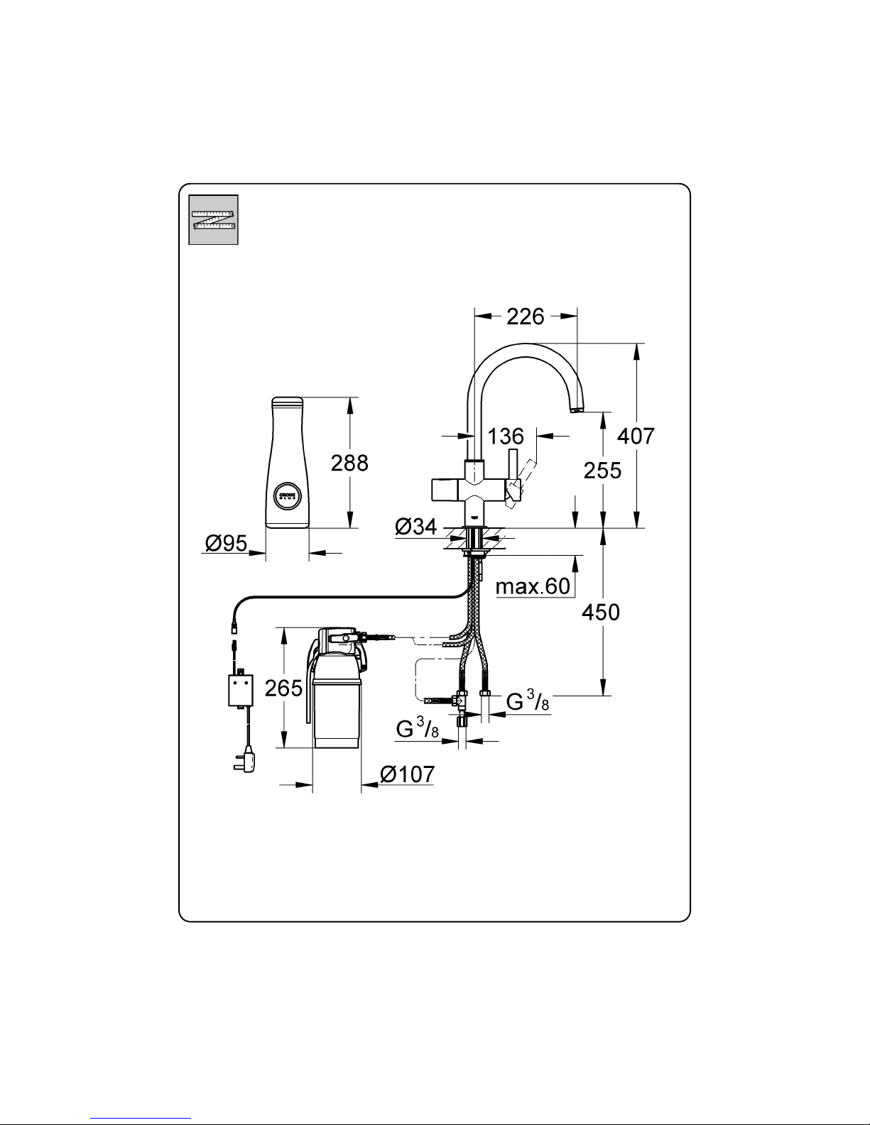
sink (for hole diameter see fold-out page VI).
Feed through hoses one at a time. Do not
damage hoses, see Fig. 2.
» Install wall holder, see (1) in Fig. 3.
Choose suitable screws and plugs if necessary.
» Set water hardness at filter head, see (1) in
Fig. 4.
Set water harness at bypass setting to local
conditions, see table on fold-out page IV. The
relevant water supplier can provide information
on the water hardness.
» Insert filter head, see (2) in Fig. 4.
» Insert filter cartridge, see Fig. 5:
The filter head (2) can be swivelled forwards by
up to 90° in the wall holder (1) to install the
cartridge.
1. Remove protective cover (5) and insert filter
cartridge (4) into filter head to the stop. Note
the installation position of the filter cartridge.
2. Turn locking handle (3) until filter cartridge is
felt locking into place.
» Install control unit, see Fig. 6 on fold-out
page III.
» Connect plug-in connector of fitting to
plug-in connector of control unit, see Fig. 7.
» Connect fitti ng, see Figs. 2 and 8:
1. Connect the pressure hose marked red to the
left service valve (hot water).
2. Fit connector (2) onto service valve on right
(cold water).
3. Connect the two short pressure hoses marked
blue (arrows point towards the fitting) to
connector.
4. Connect the long pressure hose marked blue
(arrow points towards the filter) to filter
head (1) [IN].
5. Connect the long pressure hose marked blue
(arrow points away from the filter towards
the fitting) to filter head (1) [OUT].
» Open hot and cold water supply and check
that connections are watertight.
» Flush filter cartridge, see Fig. 9:
1. Place collecting vessel (at least 2-litre
capacity) under filter to collect the water
flowing out of the hose (3).
2. Open rotation handle (1).
3. Press flush valve (2) on filter head and flush
filter system.
4. Continue flushing until the water emerging
from the hose is clear and free of bubbles
(at least 2 litres).
5. Close rotation handle.
» Connect power supp ly, see Fig. 10 on fold-out
page IV.
The red and green indicator lamps flash on and
off a number of times and then remain on.
Electrical test data
Approval and conformity
Installation
This product conforms to the requirements
of the relevant EU guidelines.
Putting into service
Page 6

4
» Set the flow rate (factory setting: 4.5 l/mi n), see
Fig. 10:
1. Place measuring beaker (1 litre) under the
spout.
2. With a finger, cover red (2) and green (3)
indicator lamps on control unit simultane ously
for 6 seconds.
The indicator in the rotation handle (1) of the
fitting flashes red.
3. Open rotation handle fully within 2 minut es
and draw off exactly 1.0 litre of filtered water.
4. Close rotation handle.
5. Quickly tap one of the two indicator lamps
twice with a finger.
Both indicator lamps flash on and off 4 t imes and
then remain on.
Repeat the entire process if the indicator lamps do
not flash on and off. Possible causes:
– Time expired (2 minutes)
– Flow rate too slow or too fast
(< 1 l/min or > 6 l/min)
– Tapping did not register
The fitting is now fully installed and ready for
operation.
»Open lever (3) to draw mixed water.
» Ope n rotation handle (1) to draw off filtered
water. The indicator in the rotation handle
indicates the filter capacity:
Filter capacity indicator (2) in rotation handle:
Note:
Replacement filter cartridges can be ordered at
www.grohe.com or from your supplier.
Inspect and clean all components and replace if
necessary.
Important:
Risk of damage:
Always disconnect the power supply before
carrying out maintenance work on the fitting.
The plug-in connectors can then be disconnected, see Fig. 7 on fold-out page III.
Cartridge, see Fig. 12 on fold-out page IV.
1. Shut off hot and cold water supply.
2. Lever out plug (6) and remove set screw (5).
3. Remove lever (4) and cap (3).
4. Remove screw coupling (2) and take out
cartridge (1).
When installing the cartridge, ensure t hat the seals
are correctly seated. Screw in screw coupling and
tighten.
Ceramic headpart, see Fig. 13 on fold-out
page IV.
1. Shut off hot and cold water supply.
2. Close rotation handle (1) and remove.
3. Remove display component (6).
4. Remove snap insert (2) and stop (3).
5. Replace complete ceramic headpart (5)
or O-ring (4).
Assemble in reverse order. Note th e installation
position of the stop.
Mousseur
Remove and clean mousseur (64 374), see
fold-out page V.
Power supply fuse of control unit:
Remove and replace fuse (3A) if the red and green
indicator lamps does not light, see fold-out page V
(available from electrical retailers).
Replacement parts, see fold-out p age V.
Operation, see Fig. 11
Flashing signal Meaning
Filter capacity of more
than 10%
Filter capacity of less
than 10%
» Order filter car tridge
Filter capacity of less
than 1%
» Change filter cartridge
soon
» No filter capacity
» Change filter cartridge
immediately
Maintenance
Replacement parts
Page 7

V
Page 8
VI
Page 9

Page 10

Page 11
 Loading...