

Page 1
956212.book Seite 1 Mittwoch, 19. Dezember 2001 8:04 08
Avensys
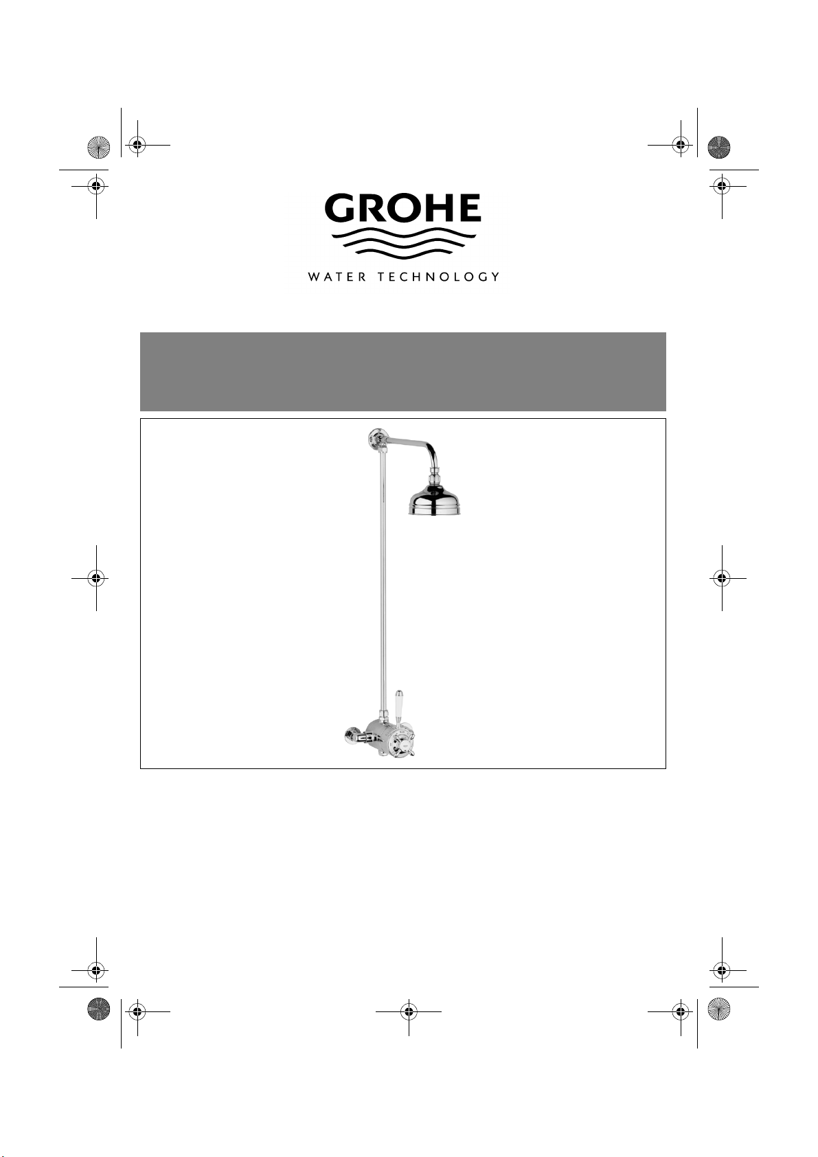
Exposed Dual Thermostat Mixing Valve
34 042
Installation Instructions and Operating Guide
Please leave this document with the user after finishing installation!
95.621.231/ÄM 41 385/12.01
Page 2
kl956212.fm Seite 1 Montag, 17. Dezember 2001 5:45 17
Table Of Contents
Wallplugs
Outlet
Nipple
Wallplugs
Screws
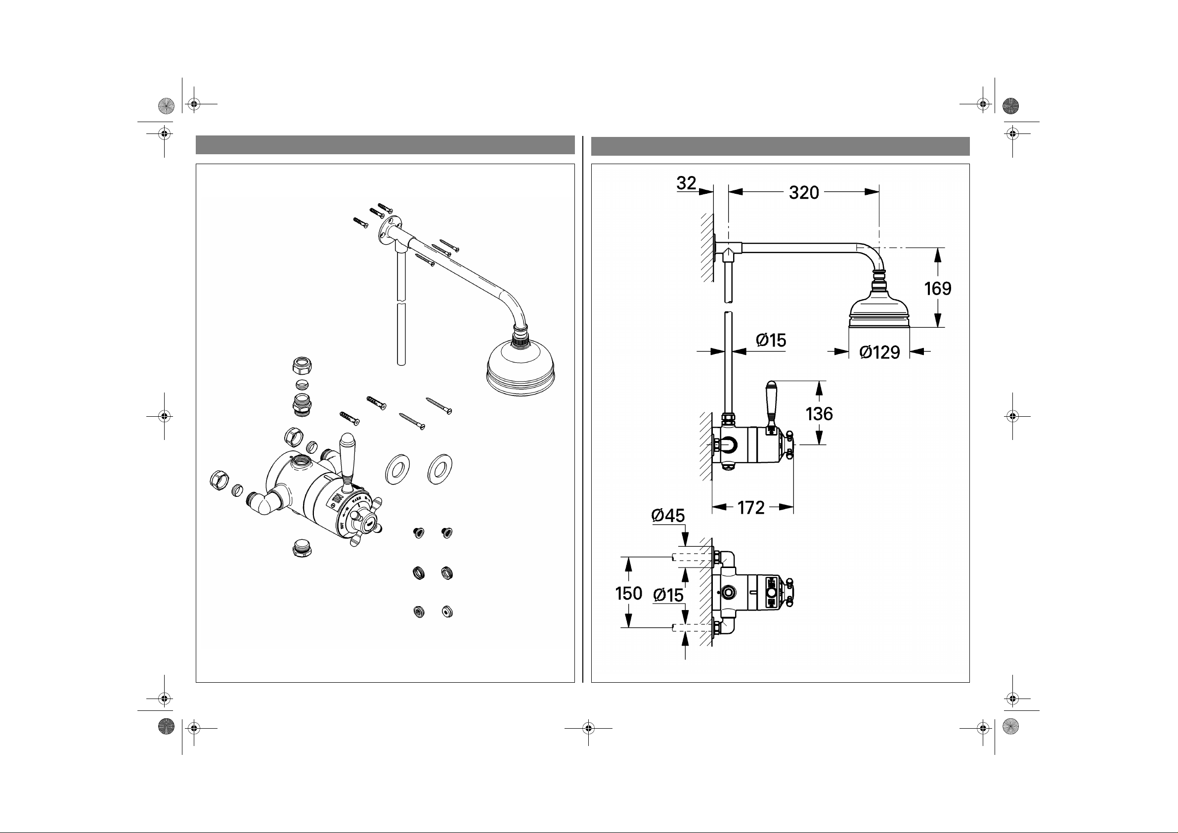
Installation Dimensions (mm)
34 042
Screws
Headshower
Backplate
Valve Body
Plug
Escutcheons
Filters
Threaded Rings
Flow Limiters
1 2
I
Page 3
kl956212.fm Seite 2 Montag, 17. Dezember 2001 5:45 17
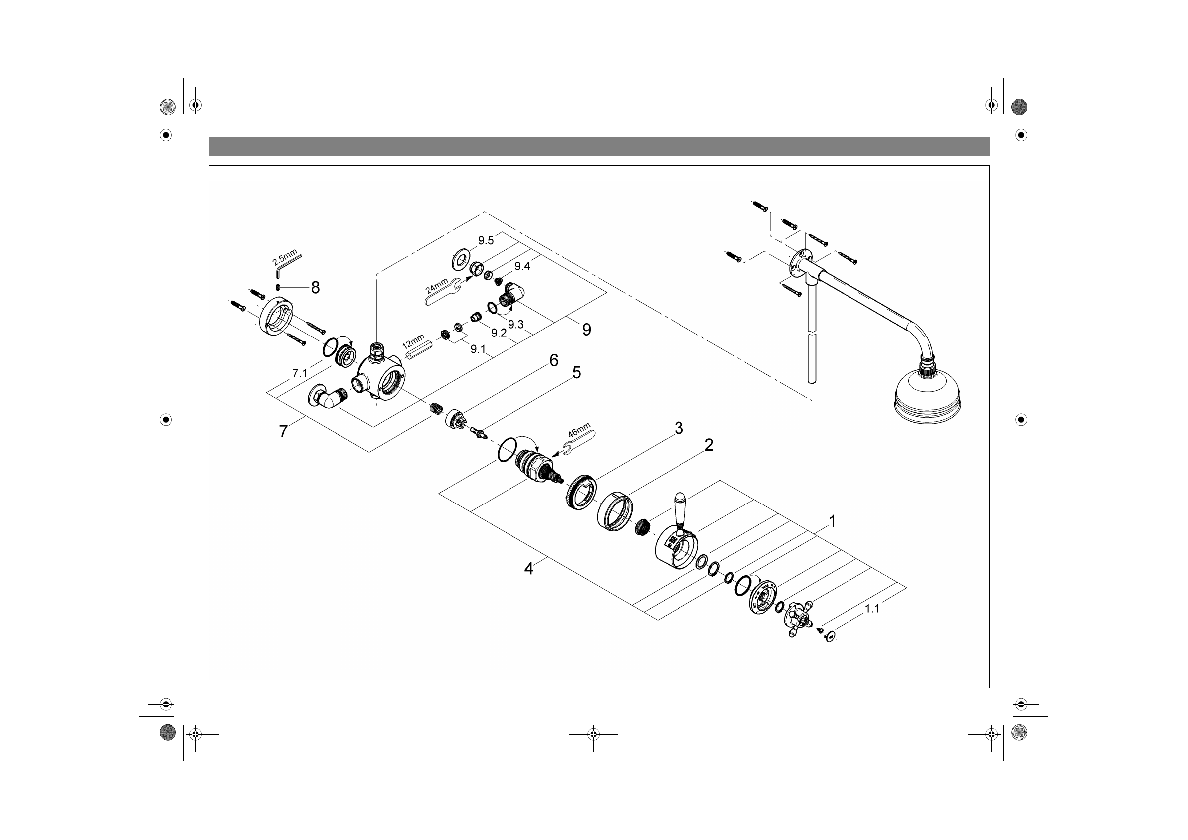
Spare Parts
II
3 4
Page 4
T
I
S
S
T
I
M
C
T
G
956212.book Seite 5 Mittwoch, 19. Dezember 2001 8:04 08
able Of Contents . . . . . . . . . . . . . . . . . 1
nstallation Dimensions . . . . . . . . . . . . 2
pare Parts Drawing. . . . . . . . . . . . 3 + 4
Index
pare Parts List. . . . . . . . . . . . . . . . . . . 5
echnical Data. . . . . . . . . . . . . . . . . . . . 6
nstallation. . . . . . . . . . . . . . . . . . . . . . . 7
Exposed Installation. . . . . . . . . . . . . . . 7
Shower Connection . . . . . . . . . . . . . . . 9
Adjustment. . . . . . . . . . . . . . . . . . . . . 10
aintenance . . . . . . . . . . . . . . . . . . . . 11
are . . . . . . . . . . . . . . . . . . . . . . . . . . . 13
rouble Shooting . . . . . . . . . . . . . . . . 13
uarantee . . . . . . . . . . . . . . . . . . . . . . 15
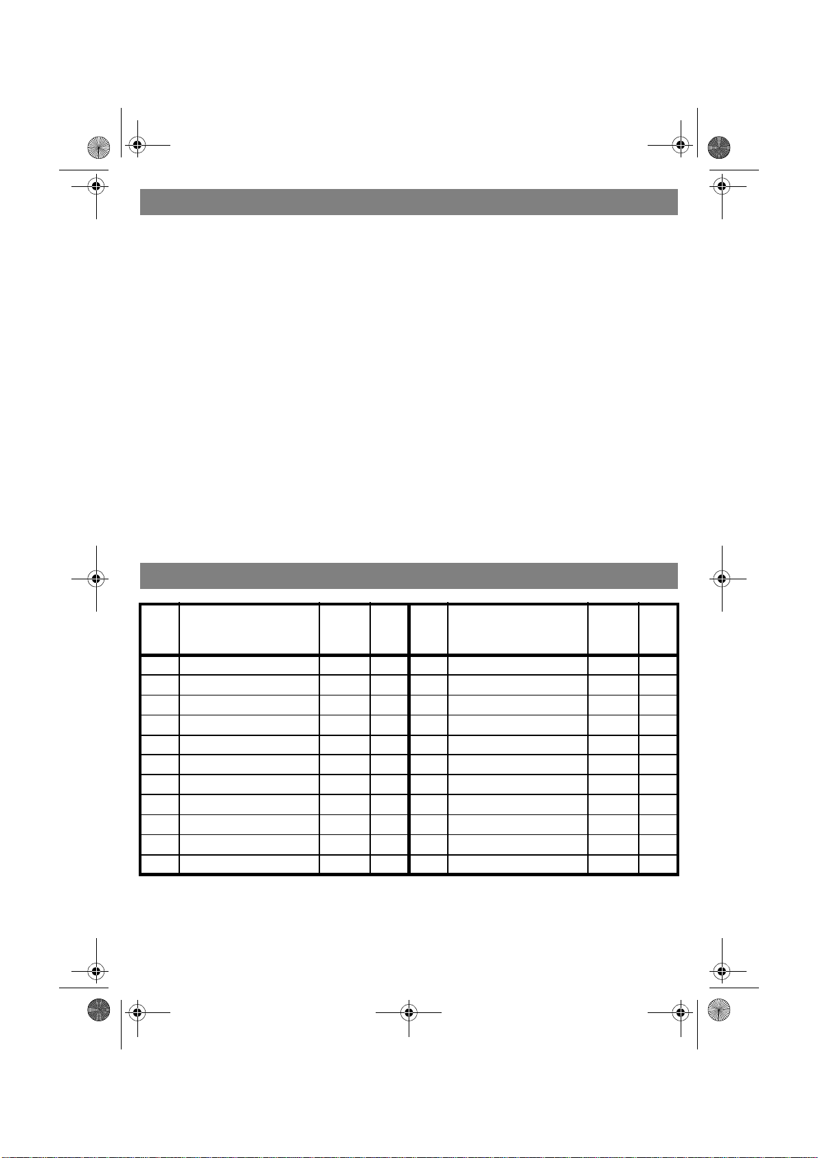
Spare Parts
No. Description Cat.-No.
1 Lever complete 47 599 1
1.1 Cap 00 090 1
2 Cover Ring 00 565 1
3 Stop ring 47 593 1
4 Control unit 47 598 1
5 Wax element 00 798 1
6 Slider 07 587 1
7 Seat with spring 47 594 1
7.1 O - ring seal 03 169 5
Dear Customer,
Thank you for choosing a GROHE product.
Please follow these instructions carefully
and you will enjoy many years of reliable
service from this fitting.
Pack-
No. Description Cat.-No.
ing
unit
8 Set screw M5x12 02 125 5
9 Connection elbow 12 111 2
9.1 Flow limiter set 46 428 1
9.2 Non-return valve 06 544 2
9.3 O - ring seal 01 287 10
9.4 Filter 06 768 5
9.5 Escutcheon 00 197 2
Packing
unit
5
Page 5

Technical Data
F
T
m
o
o
p
d
h
T
ø
l
p
P
T
i
S
E
f
G
v
s
N
T
c
c
b
r
r
r
n
r
r
C
C
H
H
unctioning Principle
his Avensys mix ing valve is a thermostatic
ixer with wax cartridge. Turning the shutff lever in a counter-clockwise direction
pens the water flow. Turning the temerature cross handle in a counter-clockwise
irection sets the temperature from cold to
ot.
his product is supplied with connectors to fit
15mm pipework. Connection should be hot
eft, cold right as viewed from the operating
osition. The product is preassembled.
lumbing Systems
his thermostatic mixing valve is sui t able f or
nstallation with:
x Gravity-fed plumbing systems with an
open vented hot water cylinder
x Cold water storage cistern
x Mains pressure unvented and instantan-
eous thermal hot water storage systems
x Multi-point gas water heaters
x Combination boilers with a modulating hot
water output
upply Pipework
nsure the supply pipework is thoroughly
lushed before installing the mixing valve.
ROHE recommends installing isolating
alves upstream of the mixing valve for
ervicing purposes.
Specification
x Exposed thermostatic shower mixing
valve, concealed or exposed supplies
x Flow pressure
- Low pressure 0.1 - 1 ba
- High pressure 1 - 10 ba
x Avoid major pressure differences betwee
hot and cold water supply:
For different supply pressures use
enclosed flow limiters, see chapter
“Exposed Installation” on page 7.
x Max. operating pressure 10 ba
x Max. test pressure 16 ba
x Mixed water flow rate without downstream
resistance:
Pressure 0.1 0.2 0.3 0.4 0.5 0.6 bar
Flow rate 5 7.2 9.2 10.6 11.9 13.0 l/min
x Temperature
- Max. (hot water inlet) 80 q
- Recommended (for economy) 60 q
- Maximum temperature is reached when
the temperature cross handle is rotated
270q in a counter-clockwise direction.
x Water connection cold - R
hot - L
ew Water Regulations
his GROHE-product should be installed to
omply with the New Water Regulations
overing backflow prevention. It must also
e installed in accordance with local bye-law
equirements.
6
Page 6
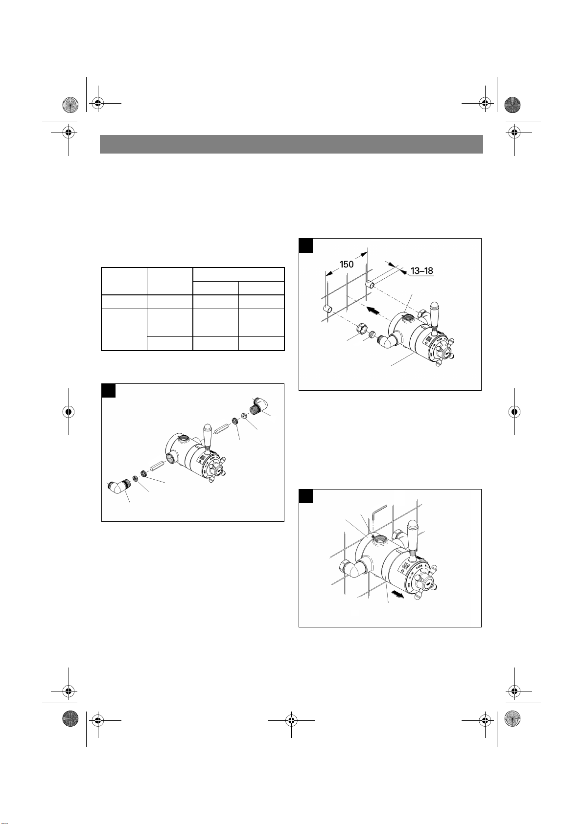
Exposed Installation
T
b
w
I
t
a
c
T
w
s
a
v
s
)
s
956212.book Seite 7 Mittwoch, 19. Dezember 2001 8:04 08
Installation
his thermostatic shower mixing valve is to
e installed with the outlet at the top for use
ith the headshower.
f there is a pressure differences between
he hot and cold water supply install
ttached flow limiters in the water
onnection elbows, see table below.
Cold Water
Inlet
0.1 - 1 bar 0.1 - 1 bar without without
1 - 5 bar 1 - 5 bar 7 l (green) 5 l (yellow)
1.5 - 10 bar 0.1 - 0.5 bar 7 l (green) without
x Screw out connection elbows (A), see
Fig. [1].
1
Warm Wa-
ter Inlet
> 0.5 bar 7 l (green) 5 l (yellow)
m
m
2
1
Connection
Cold Warm
2
1
C
B
A
m
m
B
C
In case of exposed installation with supply
pipes from above or below rotate inlet
elbows 90q and connect to 15mm supply
pipes.
1.Loosely screw on nuts (A1) with compression rings (A2), see Fig. [2].
2
D
A1
A2
E
2.Ensure that the projections of the supply
A
pipes, (i.e. exposed beyond the wall surface) have the correct length (13 - 18mm
and distance (150mm).
3.Place the valve body (E) with the elbows
and backplate (D) to the supply pipes.
4.Loosen set screw (D1), see Fig. [3].
3
D1
D
m
m
5
.
2
x Install flow limiters (B) in accordance to
table above with threaded rings (C) by
using a 12mm socket spanner.
he thermostatic mixing valve is fixed to the
all via the backplate and connected to the
upply pipes by a pair of elbows. The elbows
re preassembled to the valve body. The
E
alve body is fixed to the backplate by a set
crew.
5.Remove valve body (E) from supply pipe
and hold backplate (D) in position.
7
Page 7
6
7
8
d
If
956212.book Seite 8 Mittwoch, 19. Dezember 2001 8:04 08
Installation
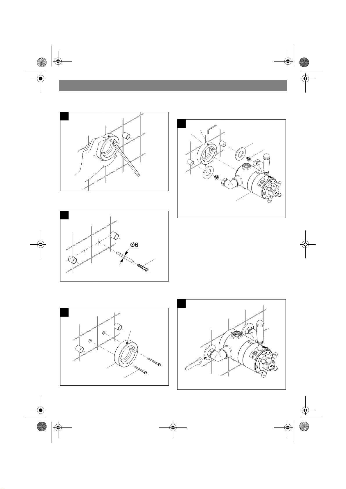
.Mark the holes in the backplate for wall-
plugs, see Fig. [4].
4
9.Slide the escutcheons (H) over the
supply pipes and install filters (J), see
Fig. [7].
7
D1
D
m
m
5
.
2
H
J
.Drill the holes (6mm) for the wallplugs (F)
and fit them into the wall, see Fig. [5].
E
5
10.S lide the valve body (E) with elbows an
compression nuts loosely over the
supply pipes.
The body must touch the backplate.
not, check pipes for length again.
F
.Fix the backplate (D) with set screw (D1)
on top or bottom to the wall with
screws (G), see Fig. [6].
6
11.Fix the valve body (E) to the back-
plate (D) by tightening set screw (D1).
Do not use excessive force to tighten
the set screw (D1).
12.Tighten the compression nuts (torque
min. 20 Nm), see Fig. [8].
8
D1
m
m
4
2
D
G
8
Page 8
S
1
2
3
Open hot and cold water supply.
.
956212.book Seite 9 Mittwoch, 19. Dezember 2001 8:04 08
Installation
hower Connection
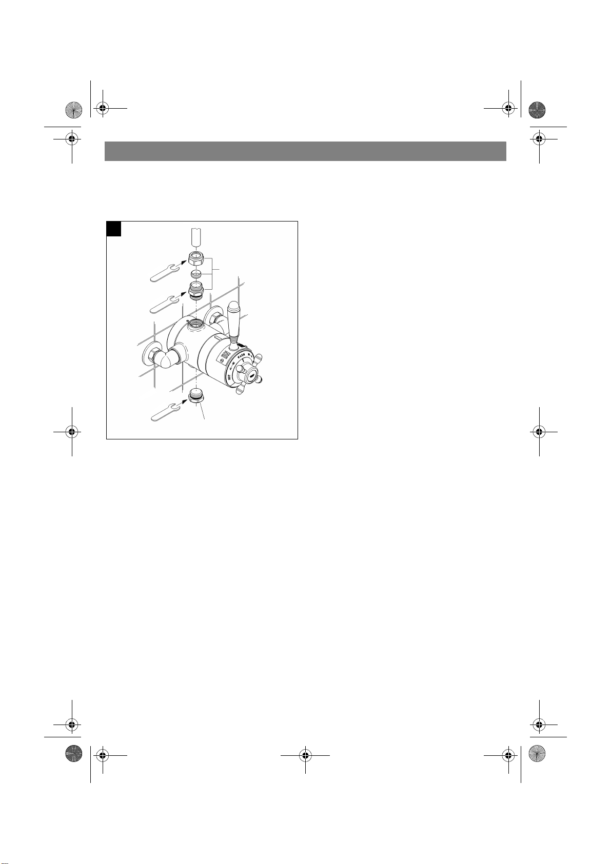
.Close bottom outlet with plug (K),
see Fig. [9].
Check the pipework and connections to the
thermostat mixing valve for leaks.
9
m
m
4
2
m
m
4
2
m
m
4
2
.Thread the outlet nipple (L) with the O-ring
seal into the valve body outlet.
.Insert pipe and tighten outlet nipple (L).
L
For reversed supplies installation the
complete mixing valve must be rotated 180q
Therefore shut-off lever, temperature cross
handle, cover ring and stop ring must be
dismounted, rotated 180q and reinstalled.
K
9
Page 9
Adjustment
T
f
m
F
p
1
2
3
r
d
956212.book Seite 10 Mittwoch, 19. Dezember 2001 8:04 08
Installation
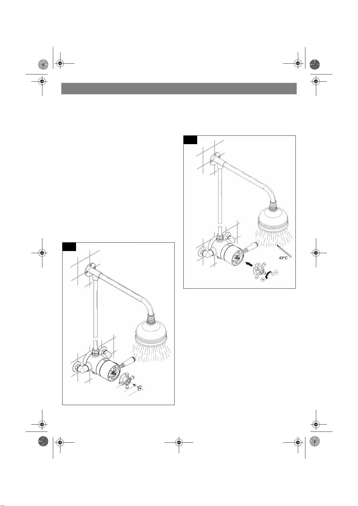
he temperature of the outflowing water is
actory set to 43 qC. A temperature adjust-
ent is necessary if:
x The maximum water temperature
measured at the outlet varies from
the factory set temperature.
x After any maintenance operation on the
thermostatic cartridge.
or temperature adjustment please
roceed as follows:
.Turn the shut-off lever counter-clockwise
to fully open position and open water flow.
.Turn the temperature cross handle
counter-clockwise to maximum hot water
temperature.
.Lever out cap (M), see fig. [10].
4.Unscrew screw (N).
5.Pull off temperature cross handle (O).
6.Check the temperature of the outflowing
water with a thermometer, see Fig. [11].
11
10
7.Push on temperature cross handle and
O
N
M
adjust temperature to 43 qC.
Turn clockwise (to reduce temperature) o
counter-clockwise (to increase
temperature).
8.Pull off temperature cross handle (O) and
reinstall in hot water position as describe
in Fig. [10] in reversed direction.
10
Page 10
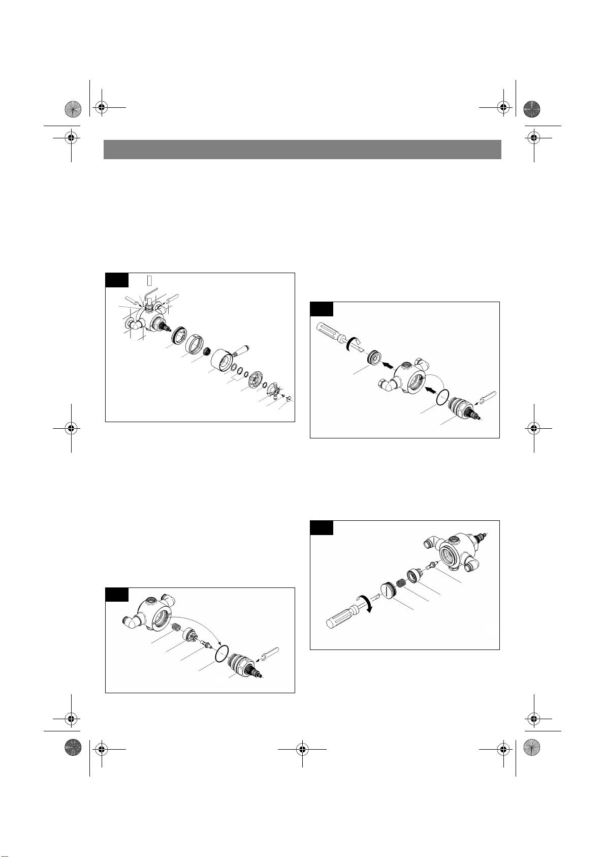
I. Control Unit
d
e
m
956212.book Seite 11 Mittwoch, 19. Dezember 2001 8:04 08
Maintenance
1.Shut off hot and cold water supply!
2.T urn the shut-off lever counter-clockwise
to fully open position and open water
flow.
3.Turn the temperature cross handle
counter-clockwise to maximum hot
water temperature.
4.Lever out cap (M), see Fig. [12].
12
D1
2
4
m
m
L
5.Unscrew screw (N).
6.Pull off temperature cross handle (O).
7.Remove circlip (P1) and pull off scale
ring (P).
8.Remove circlips (Q1), washer (Q2) and
pull off shut-off lever (Q).
9.Pull off adapter (R).
10.Pull off cover ring (S) and stop ring (T).
11.Loosen outlet nipple (L) and reinstall
shower.
12.Loosen set screw (D1).
13.Unscrew connections and take valve
from the supplies.
14.Screw out control unit (U), see Fig. [13].
13
m
5
.
2
m
m
4
2
T
S
R
Q
Q2
Q1
P
P1
O
N
M
15.Ta ke out O-ring seal (U1).
16.Take out wax element (V), slider (W) an
spring (X).
Inspect and clean all parts, replace if
necessary and grease with special valve
grease (ref. No. 18 012).
Reinstall control unit
1.Unscrew seat (Y) with O-ring, see
Fig. [14].
14
Y
m
6
4
U1
U
2.Reinstall O-ring seal (U1).
3.By turning the unit stem counter-clockwis
make sure the control unit (U) is in open
position and screw in.
4.Reinstall wax element (V), slider (W) and
spring (X) from behind, see Fig. [15].
15
V
W
X
Y
m
m
m
X
W
V
U1
U
6
4
5.Close control unit (U) by turning the unit
stem clockwise to closed position.
6.Tighten seat (Y) in the valve body.
11
Page 11
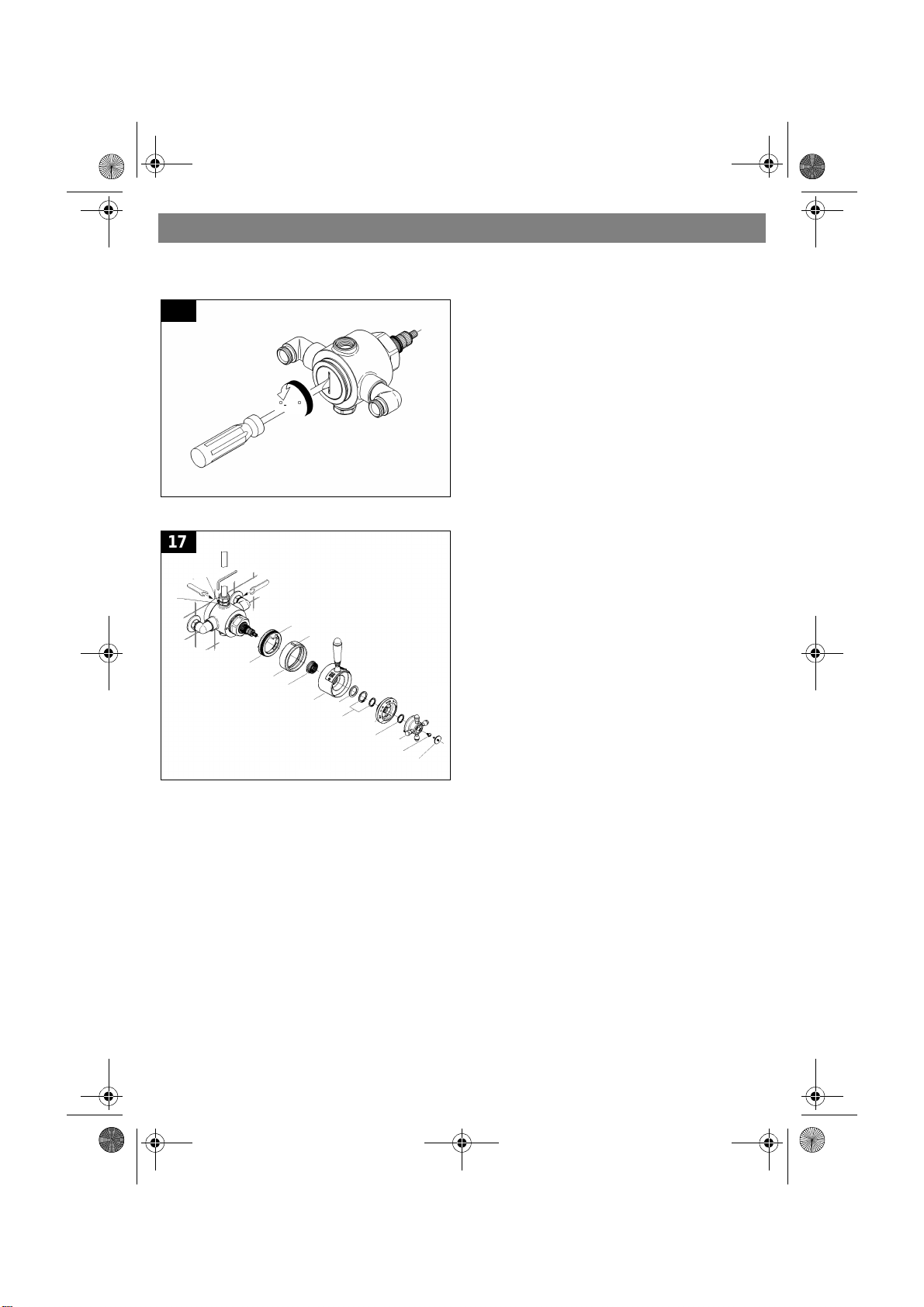
956212.book Seite 12 Mittwoch, 19. Dezember 2001 8:04 08
Maintenance
7.Unscrew seat 1/8 to 1/6 turn (45qto
60q), see Fig. [16].
16
14.Push on shut-off lever (Q) in closed
position.
15.Reinstall washer (Q2) and fix with circlips (Q1), the smaller one is to be
placed in the middle of the unit stem.
16.Push on scale ring (P) with WARM on
top and fix with clip (P1).
45q-60
q
17.Reinstall the temperature cross
handle (O) in position hot water.
18.Fix temperature cross handle with
screw (N) and cover with cap (M).
Readjustment is necessary after every
maintenance operation on the control unit,
see chapter “Adjustment” on page 10.
8.Slide valve on the supplies, see Fig. [17]
17
D1
2
4
m
m
L
m
m
5
.
2
m
m
4
2
II.Non-return valve, see spare parts
T1
S1
T
S
R
Q2
Q
Q1
P
P1
P1
O
N
M
drawing on page 3, 4 and Fig. [12].
1.Same procedure as for control unit, see
Fig. [12], points 1, 11 and 12.
2.Unscrew elbow, see spare parts drawing
on page 3 and 4.
3.Remove threaded ring with flow
limiter (9.1) if installed.
4.Take out and replace non-return
9.Tighten set screw (D1) and compression
nuts.
valve (9.2).
Reassemble in reverse order.
10.Install shower and tighten outlet
nipple (L).
11.Push on stop ring (T) with catch (T1)
on top.
12.Reinstall cover ring (S) with mark (S1)
on top.
13.Push on adapter (R).
Only genuine GROHE replacement parts
must be used.
12
Page 12
W
s
f
c
s
f
o
D
r
t
a
a
a
g
t
.
g
956212.book Seite 13 Mittwoch, 19. Dezember 2001 8:04 08
Care
e want to ensure that you get long-lasting
atisfaction and pleasure from your GROHE
itting. Therefore, please read the following
are instructions because damage to the
urface and underlying material resulting
your fitting dull and scratched. As the formulations of commercially available cleanin
agents frequently change, we cannot guarantee they will provide the gentle care our
fitting deserves.
rom improper treatment is not covered by
ur guarantee.
Clean the fitting with a little soap and a mois
cloth only , then simply rinse off and wipe dry
o not use any abrasive sponges or scouing agents for cleaning. We also advise not
o use cleaning agents containing solvent or
cid, limescale removers, household vinegar
nd cleaning agents with acetic acid. They
re aggressive to the surface and will leave
You can avoid lime spots by drying the fittin
each time it is used. If lime deposits do occur, remove them with Grohclean (ref. no.
18 078), our environment-friendly cleaning
liquid. Grohclean is specially formulated to
gently clean the surface of our fittings.
Trouble Shooting
Problem Cause Remedy
Thermostatic valve
opens through hot
Range of temperature
adjustment restricted
Hot and cold water supplies have
been connected in reverse
High pressure difference between
hot and cold water supply
Rotate the thermostatic mixing
valve
Install flow limiter see chapter
Exposed Installation
Shower insufficiently
cold or hot
No flow of hot or cold
water
Hot water emerges to
cold water supply or
vice versa
Adjustment incorrectly set
Hot water supply temperature too
low
Either the hot or cold side is not
fully pressurized
Debris caught inside the inlet of
the control unit
Non return valves are damaged in
cause of lime
13
Refer to the instructions in chapter
Adjustment
Check hot water source temperature setting
Replace non-return valve, refer to
chapter Maintenance
Remove mixing valv e and flush out
or remove any debris lodged inside the hot or cold inlets or filters
Replace non-return valve, refer to
chapter Maintenance
Page 13
956212.book Seite 14 Mittwoch, 19. Dezember 2001 8:04 08
14
Page 14
Guarantee declaration
O
n
t
g
p
t
w
r
G
-
-
T
c
T
c
r
g
i
Guarantee performance
ll
y
ll
.
,
e
t
e
y
e
r
d
956212.book Seite 15 Mittwoch, 19. Dezember 2001 8:04 08
Guarantee
ur products correspond to the valid tech-
ical and water supply standards as well as
he relevant approvals requirements. We
uarantee them to be free of design and
roduction faults at the time of delivery and
hat with correct use and care in accordance
ith our printed instructions they will function
eliably.
uarantee period
The guarantee is valid in private homes for
5 years from the purchase date. Proof of
purchase has to be provided when making
a guarantee claim.
By use in commercial or institutional appli-
cations the guarantee is valid for 1 year
after first use. An extension of the
guarantee up to 5 years can be achieved
by showing that the product is
professionally maintained each year.
o make a guarantee claim, proof of purhase or, the beginning of use is required.
he guarantee period is not renewed or in-
reased through supply of spare parts or
epair during the guarantee period. The
uarantee period for purchased spare parts
s the same as for original products.
Please enter date of purchase and installation here.
A)During the whole guarantee period we wi
correct all functional defects for which we
are responsible (limitations see E + F).
B)It is our option if we correct the defects b
repair or replacement.
C)During the above guarantee period we wi
not charge for the cost of parts, travel,
working time, freight and packaging
needed to effect the correction of defects
D)If we are not able to correct the defect we
are prepared to supply a replacement
product.
E)Deliberate or careless damage is not co-
vered by this guarantee. If the installation
assembly or care instructions that were
valid at the time of installation are not followed or the product is used for a purpos
other than that given in the written information the guarantee declaration does no
apply . Problems caused by dirt, lime-scal
or aggressive cleaners are not covered b
the guarantee.
F)The guarantee becomes void if repairs ar
not carried out competently or spare parts
of non GROHE origin are used.
G)Replaced parts become the property of
GROHE and are to be surrendered to ou
service personnel or sent to our registere
offices.
Our address
GROHE Limited
1, River Road
Barking,
Essex, IG11 OHD
GB
Tel.: 0208 / 594 72 92
Fax: 0208 / 594 88 98
© 2000 Friedrich Grohe AG & Co. KG
Friedrich Grohe AG & Co. KG · P.O. Box 136 1 · 58653 Hemer/Germany
Tel. (0) 23 72 / 93 - 0 · Fax: (0) 23 72 / 93 13 22
15
 Loading...