

Page 1
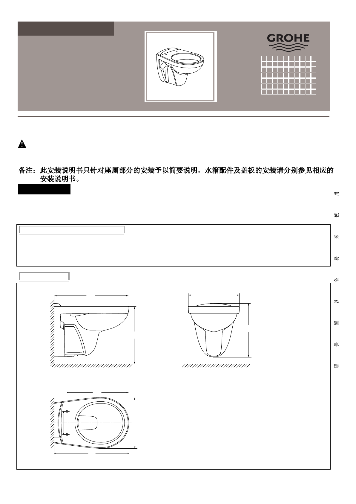
挂墙式座厕安装说明书
39320000
99.0575.031/ECN 235920/11.15
安装说明书
感谢阁下选用我们的产品……我们的产品多年来一直是优良质量的标志。为了有助于安装顺利进行,
请您在开始安装之前仔细阅读这些指南,也请查阅推荐的工具和材料表;小心打开您的新产品。
警告:易碎产品。小心轻放以避免产品破碎和人身伤害。
注意:图片可能与真实产品不符(请以实物为准)。
所有的安装程序必须严格遵从当地的卫浴和建筑法规条例。
备注:此安装说明书只针对座厕部分的安装予以简要说明,水箱配件及盖板的安装请分别参见相应的
安装说明书。
使用注意事项
1、请不要向便器内冲入新闻纸、纸尿垫、妇用卫生巾等容易堵塞的物品。
2、请不要用重力撞击陶瓷,以防止破损漏水。
3、不要在零摄氏度以下水的环境中使用。
推荐工具和材料 (客户自备)
油泥刀
扳手
冲击钻
可调扳手
水平尺
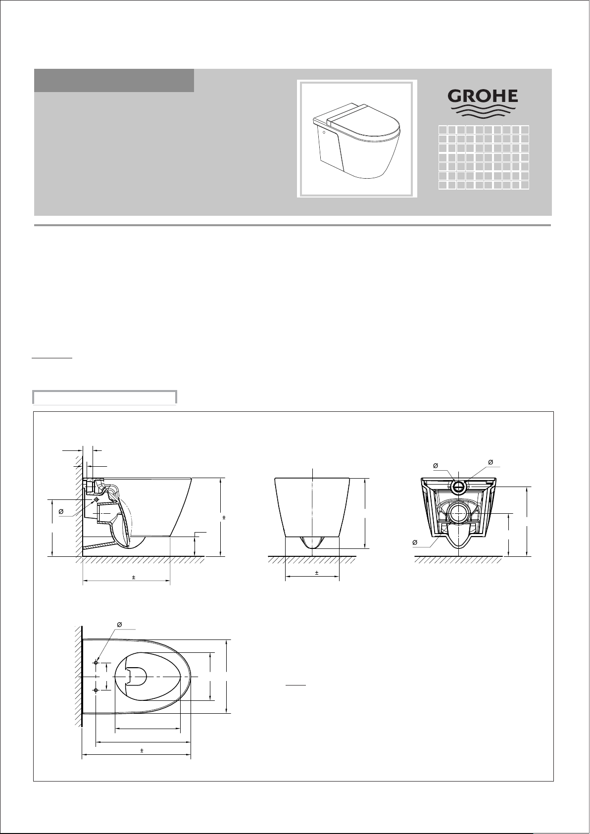
基 本 尺 寸
520
完成墙面
430
完成墙面
155
520
400
355
鲤鱼钳
钢锯
卷尺矽胶
355
用水量: 3/6升
额定用水效率等级:3级
标准号: GB25502-2010
每种型号的产品都提供了尺寸图。
注意:该产品尺寸图仅供参考,产品具体尺寸
可能在公差范围尺寸内有所变化。
十字型螺丝起子
一字型螺丝起子
370
完成地面完成地面
单位 : 毫米
- 1 -
Nov.15
Rev.02
Page 2
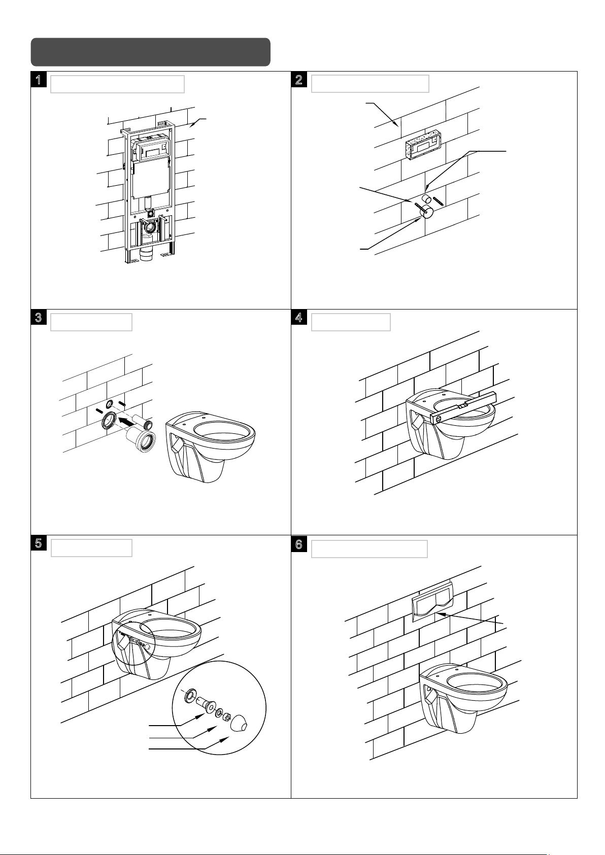
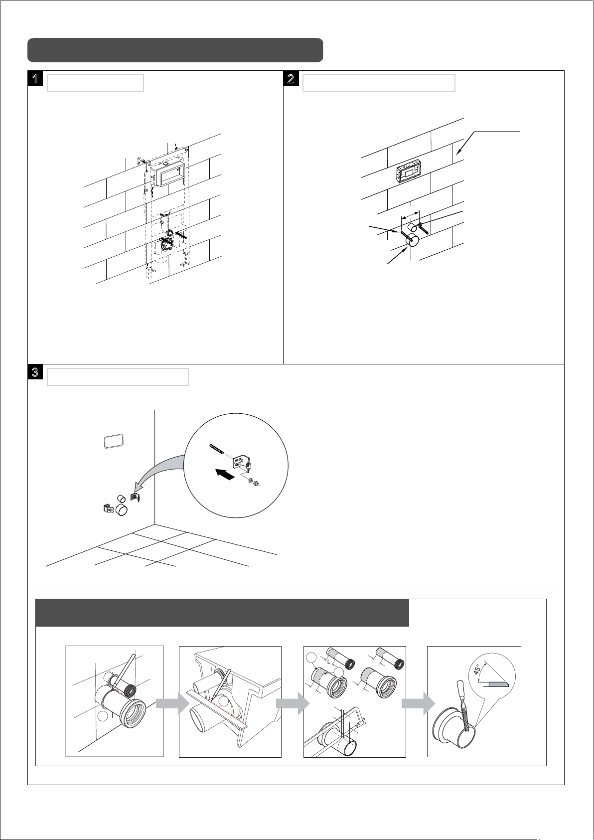
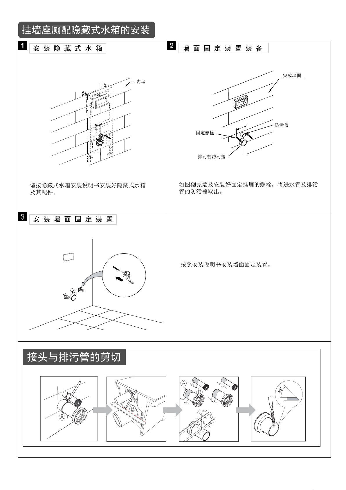
挂墙座厕配隐藏式水箱的安装
1
安 装 隐 藏 式 水 箱 安 装 固 定 装 置
内墙
请按隐藏式水箱安装说明书安装好隐藏式水箱
及其配件。(不提供在包装内,客户需自行购买)
3
附 件 安 装
2
完成墙面
固定螺栓
排污管防污盖
如图砌完墙及安装好固定挂厕的螺栓,将进水管及排污
管的防污盖取出。(参见隐藏式水箱安装说明书)
4
检 测 水 平
防污盖
按照隐藏式水箱安装说明书,将进水连接管
和排污管安装到墙面。
5
固 定 座 厕
橡胶套
六角螺母
装饰盖
用固定螺栓锁紧座厕,然后盖上塑料装饰盖。 按照隐藏式水箱安装说明书安装及调节排水按钮。
如图将挂厕装上,用水平尺检测是否水平。
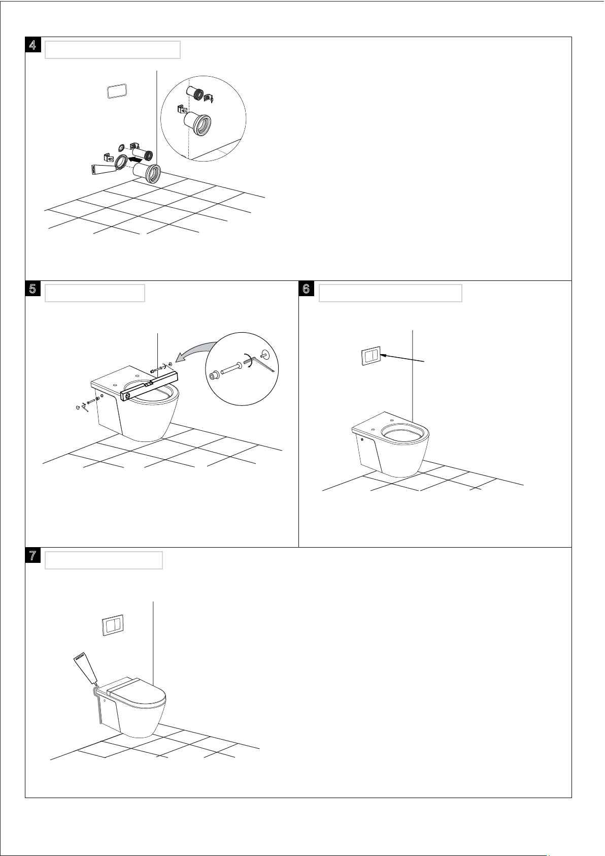
6
调 节 排 水 按 钮
排水按钮
- 2 -
Page 3
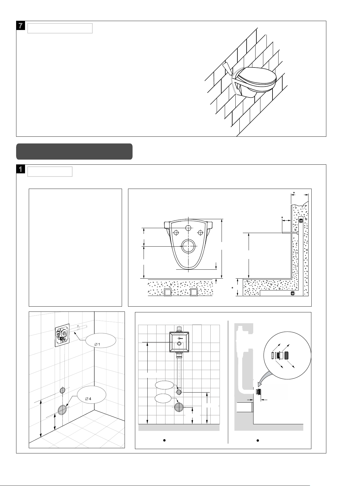
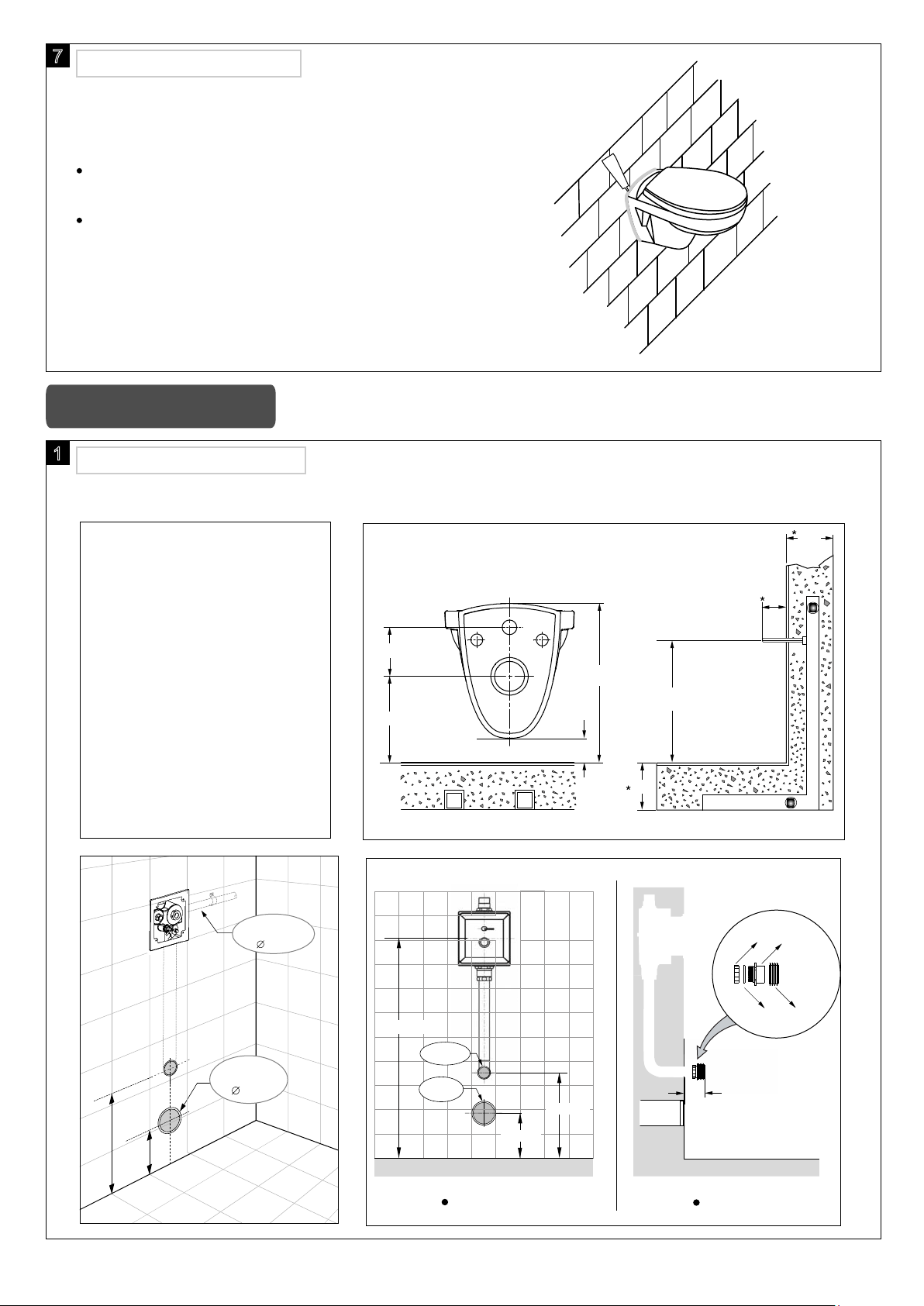
7
安 装 座 厕 盖 板
矽 胶
按照盖板的说明书安装好盖板。
在座厕底部边缘涂上矽胶(不提供)。
注意:严禁使用水泥固定座厕
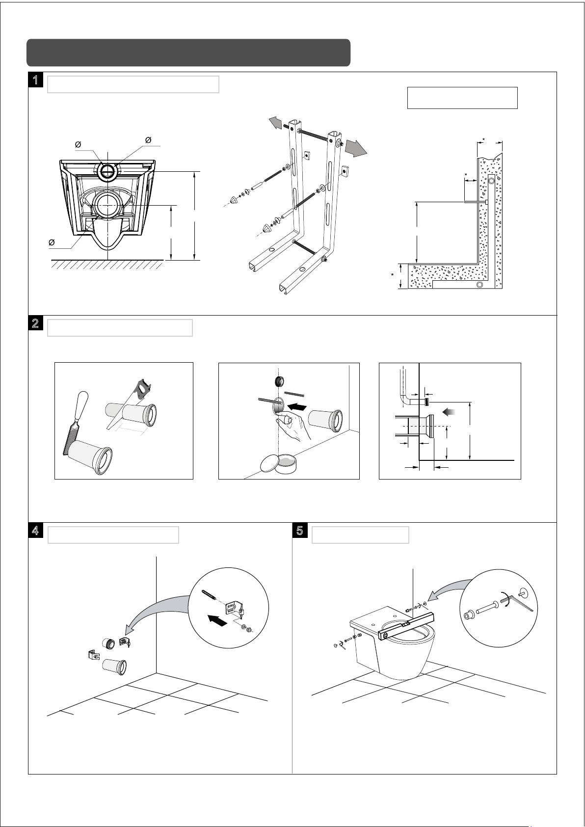
挂墙座厕配感应器的安装
1
安 装 准 备
按图示预埋安装支架和感应器,预埋好进水管和PVC排污管。(不提供在包装内,客户需自行购买)
安装支架
进水管
英寸
135
220
完成地面
120
50
完
400
320
50
120
*建议尺寸
成
墙
面
完成地面
单位:毫米
锁紧螺母 六角转接头
355
220
排污管
英寸
单位:毫米
940±20
完成地面
进水管
排污管
- 3 -
前视图
220
355
排污管
完
成
墙
面
65
侧视图
橡胶垫片 橡胶垫圈
完成地面
单位:毫米
Page 4
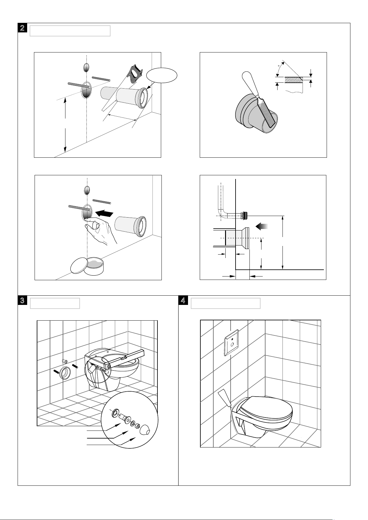
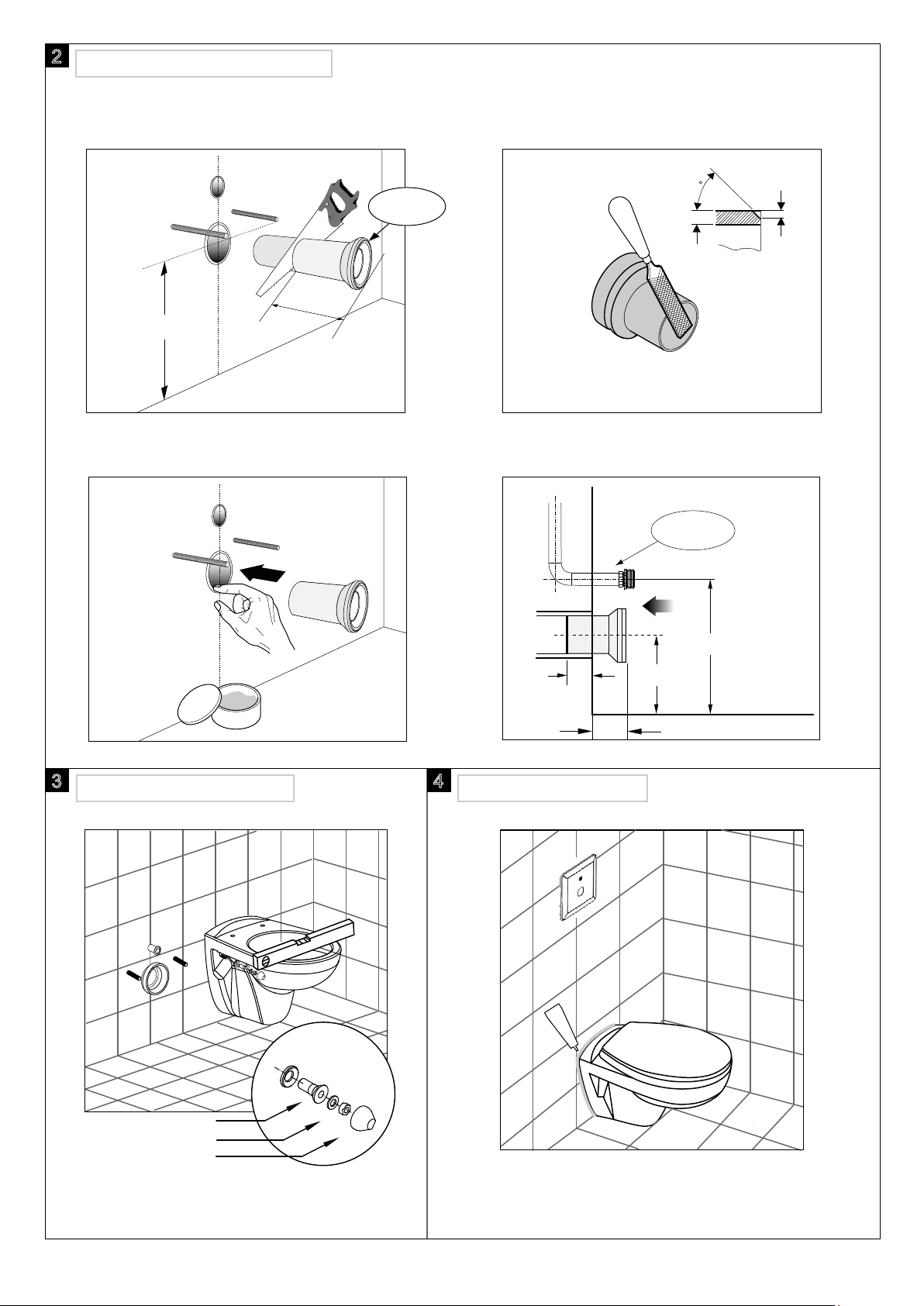
2
安 装 排 污 连 接 管
2.1 切割 2.2 削尖
3170000179
105
220
单位:毫米
2.3 打PVC胶 2.4 安装
完成墙面
45
C
C/2
单位:毫米
50-55
3
座 厕 就 位 座 厕 安 装 完 成
4
矽 胶
355
220
完成地面
50-55
橡胶套
六角螺母
装饰盖
座厕就位,用水平尺检查水平,并用固定螺栓
锁紧座厕,然后盖上塑料装饰盖。
按照感应器和盖板安装说明书完成感应器面板
安装,盖板安装,并打上矽胶(不提供)。
- 4 -
Page 5
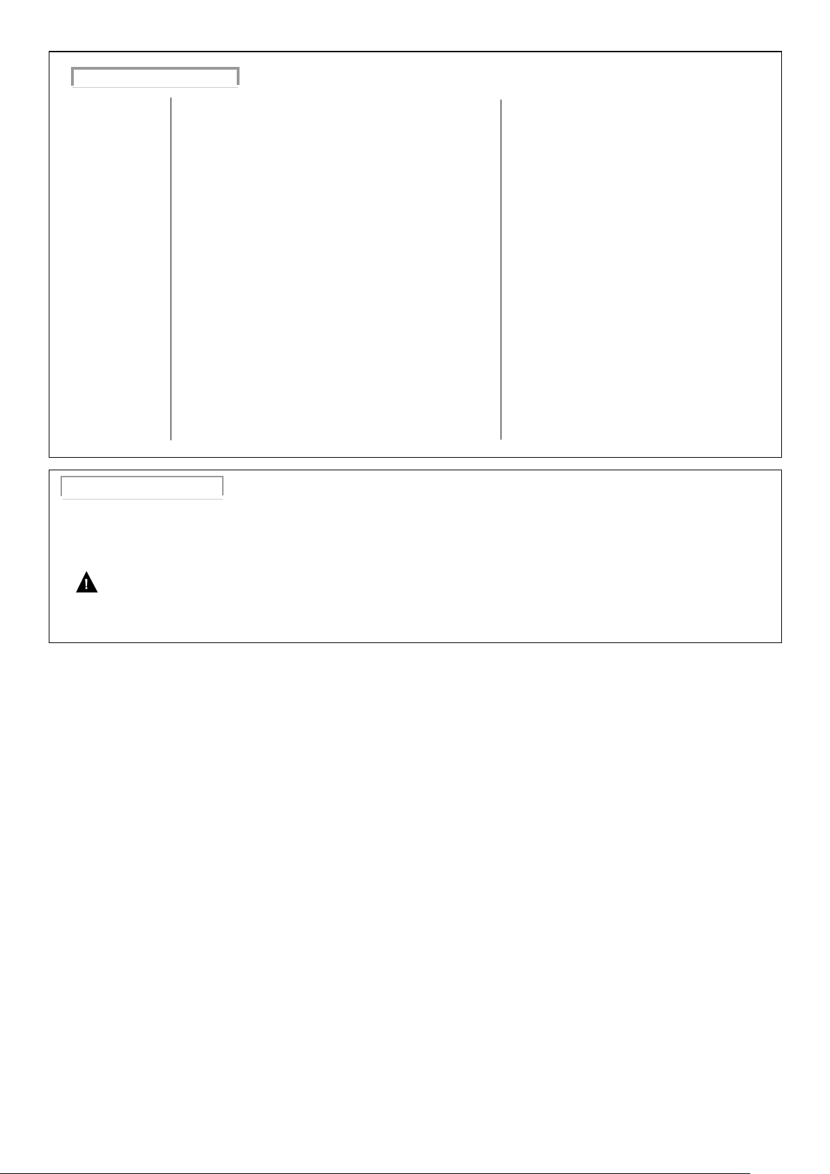
一般故障排除指南
问题描述
1. 冲水不良
2. 漏水
3. 进水管漏水
a. 水位线比要求的低
b. 冲水阀拍盖关闭过快或没打开
c. 冲水按钮或手柄损坏需更换
d. 水压过低
e. 座厕排污水道或排污管堵塞
f. 使用水箱清洁剂有沉淀物
g. 楼房无管道排气孔
a. 水位过高,高于水件溢水口
b. 关闭进水角阀,若水仍不断渗入座厕,检查出水拍盖
是否变形,或橡胶密封不良
c. 关闭进水阀,水位线低于水件溢水口,若水仍不断渗
入座厕,进水阀止水阀内可能有脏物
d. 控制出水阀拍盖装置,收得太紧导致拍盖无法关严
e. 冲水阀手柄式按钮需更换
a. 安装不良
b. 水压过高
潜在原因
解决办法
a. 重新调整水位至正确水位线
b. 检查有无脏物附着在出水阀拍盖
c. 更换
d. 正常水压必须高于20psi
e. 清理堵塞
f. 清理水箱,停止使用水箱清洁剂
g. 安装管道排气孔
a. 重新调整水位至正确水位线
b. 更换或调整橡胶密封圈或根据需要更换出水阀
c. 关闭进水阀,卸下进水阀塑料帽,清洁后重新
安装或更换止水阀阀芯
d. 更换出水阀
e. 更换
a. 根据安装说明重新安装
b. 水压不得超过80psi
保 养 和 清 洁
当您清洁座厕时,请使用温和的肥皂水,然后用清水清洁并使用软布擦干。避免使用洗洁精、消毒剂,避免在
气雾剂容器内清洁产品。杜绝使用颗粒状的清洁粉末或者在座厕上放置粗糙的座垫。一些浴室的化学药品和化
妆品可能有害于座厕的光洁。
警 告
不要在水箱内使用清洁剂,含氯(次氯酸钙)的清洁剂会严重破坏水箱内的装置,从而引起渗漏或楼宇结构损
坏。公司不会对由于使用此种含氯(次氯酸钙)的清洁剂而损坏水箱内装置负责或赔偿。
- 5 -
Page 6
D
D
+
49 5
impre
A
A
+43 1 68060
AUS
AUS
Arg ent
+(02) 8394 5 800
Ar gen t
Ar gen t
+(03) 9682 1 231
B
+32 16 230660
3989
71
ssum
@grohe.de
Sy dney
Mel bourne
333
BG
359 2 9719959
+
grohe-bulgaria@grohe.com
CAU
+99 412 497 0 9 7 4
CDN
+1 888 6447643
info@grohe.ca
CH
CH
+41 448777300
info@grohe.ch
CN
+86 21 63758878
CY
+357 22 465200
info@grome.com
CZ
+420 277 0 04 1 90
DK
+45 44 656800
grohe@grohe.dk
E
+34 93 3368850
grohe@grohe.es
EST
+372 6616354
grohe@grohe.ee
F
+33 1 49972900
FIN
FIN
+358 10 8201100
teknocalor@teknocalor.fi
GB
+44 871 200 3 414
GR
+30 210 2712908
H
+36 1 238 8045
HK
+852 2969 7 067
info@grohe.hk
I
+39 2 9594 01
IND
+91 124 4933000
IS
+354 515 4 000
jonst@byko.is
J
+81 3 32989730
KZ
+7 727 311 0 7 3 9
LT
+372 6616354
grohe@grohe.ee
LV
+372 6616354
grohe@grohe.ee
MAL
+1 800 80 6570
info-singapore@grohe.com
N
+47 22 072070
grohe@grohe.no
NL
+31 79 3680133
NZ
/
373 4 324
+09
P
+351 234 529620
PL
+48 22 5432640
RI
+62 2 1 2 358 47 51
RO
+40 2 1 2 125050
ROK
+82 2 559 0790
RP
+63 2 8041617
RUS
+7 495 9819510
info@grohe.ru
S
+46 771 141314
grohe@grohe.se
SGP
+65 6 7385585
SK
+420 277 0 04 1 90
T
+66 2610 3 685
TR
+90 216 441 2 3 7 0
GroheT [email protected]
UA
+38 44 5375273
USA
+1 800 4447643
us-customerservice@grohe.com
VN
+84 8 5413 6 840
AL
B iH
ME MK SLO
+385 1 2911470
adria-hr@grohe.com
Eastern Med i te rra nea n,
Mid d le Ea s t - A f r ica
Area Sales O ffi ce:
+357 22 465200
info@grome.com
IR
+971 4 3318070
grohedubai@grome.com
Far East Area Sales Office:
+65 6311 3 600
O M
HR
KS
SRB
UAE YEM
www.grohe.com
2014/ 03/21
Page 7
Toilet Installation manual
39320000
99.0575.031/ECN 235920/11.15
Remark: This installation manual is only for installing the ceramic parts. For the tank trim or seat & cover installing,
please refer to relative manual.
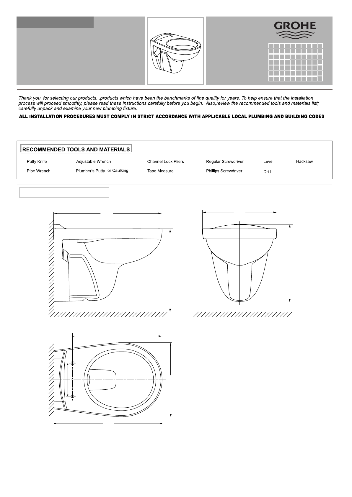
ROUGH-IN DIMENSIONS
Finished wall
Finished wall
155
520
Unit: mm
355
370
400
Finished floorFinished floor
430
S A V E F O R F U T U E R U S E
355
520
Dimensioning diagrams are provided for each model.
Note: dimensions are nominal and may vary within the range of manufacturing tolerances.
Product names listed herein are trademarks of American Standard Inc.
- 1 -
Nov.15
Rev.02
Page 8
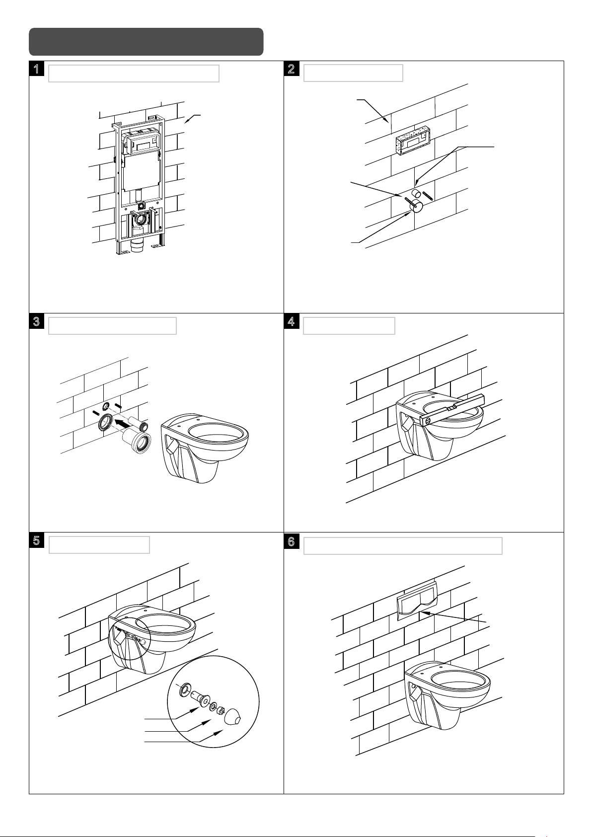
Installation of concealed tank
1
INSTALL CONCEALED TANK
Finished wall
Install concealed tank and tank fittings according to
concealed tank installing instructions, and pre-install
the expansion bolts. (Not supplied in the package)
3
INSTALL THE TOILET
2
INSTALL BOLTS
Finished wall
Cover for
water inlet
Fixing bolts
Cover for
water outlet
According to the picture shown, finish the wall and install
the bolts, then pull out the cover of water inlet and water
outlet. (Refer to concealed tank manual)
4
CHECK LEVEL
Install water inlet and water outlet according to
concealed tank install instruction.
5
FIX THE TOILET
Rubber washer
Nut
Bolts cap
Tighten the bolts to fix the toilet as picture shown,
then cover the bolts cap.
Install the toilet refer to the picture shown, and check level.
6
INSTALL THE TOP PUSH BUTTON
Push button
Install the top push button according to concealed
tank installation manual.
- 2 -
Page 9
7
INSTALL SEAT&COVER
Install the seat & cover according to seat & cover
installation manual.
Apply a silicone putty(not supplied) along the
intersecting edge of the toilet base, ensuring a
complete seal. Remove excess sealant.
Note: Using cement to fix the toilet is prohibited.
Install the sensor
1
INSTALL PREPARATION
Suggested dimension
Unit:mm
矽 胶
120
50
355
220
Bracket set
Waste pipe
Water supply
1”
4”
135
220
Finished floor
940±20
Finished floor
Water
supply
Waste
pipe
220
355
400
Tighten
nut
Rubber
washer
Finished floor
Finished wall
Convertor
Rubber
gasket
320
50
120
Waste
pipe
Finished floor
Finished wall
65
Unit:mm
Front view
- 3 -
Side view
Unit:mm
Page 10
2
INSTALL THE CONNECTOR
2.1 Cutting
3170000179
105mm
220mm
2.2 Nibbing
2.3 Applying PVC cement 2.4 Installing
Finished wall
45
C
Water
supply
C/2
3
POSITION THE TOILET
50-55mm
4
FINISH THE TOILET
Silicone
355mm
220mm
Finished floor
50-55mm
Rubber washer
Nut
Bolts cap
Tighten the bolts to fix the toilet as picture shown,
then cover the bolts cap.
Install the sensor and seat & cover according to
sensor and seat & cover installation instructions.
(Silicone is not supplied in the packaging.)
- 4 -
Page 11
TROUBLE SHOOTING GUIDE
Using this guide and referring to the accompanying instructions should help you solve most
common problems encountered.
Problem Possible Cause To Correct
1. Poor flushing action
a. Water level in tank is below prescribelevel.
b. Flush valve mechanism in tank closes too quickly
or does not open.
c. Flush handle or button needs replacing.
d. Water pressure is too low.
e. Partially clogged trapway and / or drainpipe.
f. Cleanser used in tank deposits residue.
g. No air vent.
a. Set to prescribed level.
b. Make sure there are no any material stuck
to outlet components.
c. Replace.
d. Normal water supply pressure must be at least
20 psi.
e. Use a plunger or toilet augur to unclog.
f. Clean out tank and cease using the cleanser.
g. Install air vent per instructions.
2. Water won’t stop
running
3. Water supply hose
leaks
a. Water level in tank is higher than overflow pipe.
ot seuni tnoc retaw fI .ylppus retaw eht ffo nruT .b
flow into the bowl the flush valve seat and / or
rubber seal disk are worn or deforme d.
c. Turn off the water supply valve. If water continues
to flow into the bowl until the water level falls to
be lodgeg in the water control mecha nism.
d. Flush valve string is too tight, holding the flush
valve open.
e. Button needs replacing.
a. Improper installation
b. Water pressure is too high.
a. Adjust the cylinder to maintain the water at the
prescribed level.
b. Replace seat, rubber seal disk, or complete
assembly, as needed.
c. Shut off water supply valve. Remove top cap
of water control. Clean and reassemble, or
yam sirbed ro dnas ,epip wolfrevo eht fo level eht
replace plunger.
d. Replace fulsh valve unit.
e. Replace button.
a. Reinstall, according to instructions.
b. Water pressure must not exceed 80 psi.
CARE AND MAINTENANCE
Do not use harsh abrasives or caustic cleansers to clean fixture surface. A mild detergent, warm water, and a
softcloth will remove normal dirt and soap accumulations from fittings and surfaces. Rinse thoroughly after
cleaning and polish with a soft dry cloth to restore original luster of material.
Notice
Do not use cleansers in tank. Products containing chlorine (calcium hypochlorite) can seriously damage fittings
inthe tank. This damage can cause leakage and property damage. Shall not be responsible or liable for any
tank fitting damage caused by the use of cleaners containing chlorine (calcium hypochlorite).
- 5 -
Page 12
D
D
+
49 5
impre
A
A
+43 1 68060
AUS
AUS
Arg ent
+(02) 8394 5 800
Ar gen t
Ar gen t
+(03) 9682 1 231
B
+32 16 230660
3989
71
ssum
@grohe.de
Sy dney
Mel bourne
333
BG
359 2 9719959
+
grohe-bulgaria@grohe.com
CAU
+99 412 497 0 9 7 4
CDN
+1 888 6447643
info@grohe.ca
CH
CH
+41 448777300
info@grohe.ch
CN
+86 21 63758878
CY
+357 22 465200
info@grome.com
CZ
+420 277 0 04 1 90
DK
+45 44 656800
grohe@grohe.dk
E
+34 93 3368850
grohe@grohe.es
EST
+372 6616354
grohe@grohe.ee
F
+33 1 49972900
FIN
FIN
+358 10 8201100
teknocalor@teknocalor.fi
GB
+44 871 200 3 414
GR
+30 210 2712908
H
+36 1 238 8045
HK
+852 2969 7 067
info@grohe.hk
I
+39 2 9594 01
IND
+91 124 4933000
IS
+354 515 4 000
jonst@byko.is
J
+81 3 32989730
KZ
+7 727 311 0 7 3 9
LT
+372 6616354
grohe@grohe.ee
LV
+372 6616354
grohe@grohe.ee
MAL
+1 800 80 6570
info-singapore@grohe.com
N
+47 22 072070
grohe@grohe.no
NL
+31 79 3680133
NZ
/
373 4 324
+09
P
+351 234 529620
PL
+48 22 5432640
RI
+62 2 1 2 358 47 51
RO
+40 2 1 2 125050
ROK
+82 2 559 0790
RP
+63 2 8041617
RUS
+7 495 9819510
info@grohe.ru
S
+46 771 141314
grohe@grohe.se
SGP
+65 6 7385585
SK
+420 277 0 04 1 90
T
+66 2610 3 685
TR
+90 216 441 2 3 7 0
GroheT [email protected]
UA
+38 44 5375273
USA
+1 800 4447643
us-customerservice@grohe.com
VN
+84 8 5413 6 840
AL
B iH
ME MK SLO
+385 1 2911470
adria-hr@grohe.com
Eastern Med i te rra nea n,
Mid d le Ea s t - A f r ica
Area Sales O ffi ce:
+357 22 465200
info@grome.com
IR
+971 4 3318070
grohedubai@grome.com
Far East Area Sales Office:
+65 6311 3 600
O M
HR
KS
SRB
UAE YEM
www.grohe.com
2014/ 03/21
Page 13
WALL HUNG TOILET
挂墙式座厕安装说明书
39321000
39321000
99.0575.031/ECN 235920/11.15
Installation Manual
Thank you for selecting our products which have been the benchmarks of fine quality for years.To help
ensure that the installation process will proceed smoothly, please read these instructions carefully before
you begin. Also review the recommended tools and materials in the list, carefully unpack and examine
your new plumbing fixture.
ALL INSTALLATION PROCEDURES MUST COMPLY IN STRICT ACCORDANCE WITH APPLICABLE LOCAL PLUMBING AND BUILDING CODES.
Remark : This installation manual is only for installing the ceramic parts. For the tank or seat & cover
installation, please refer to its respective manual.
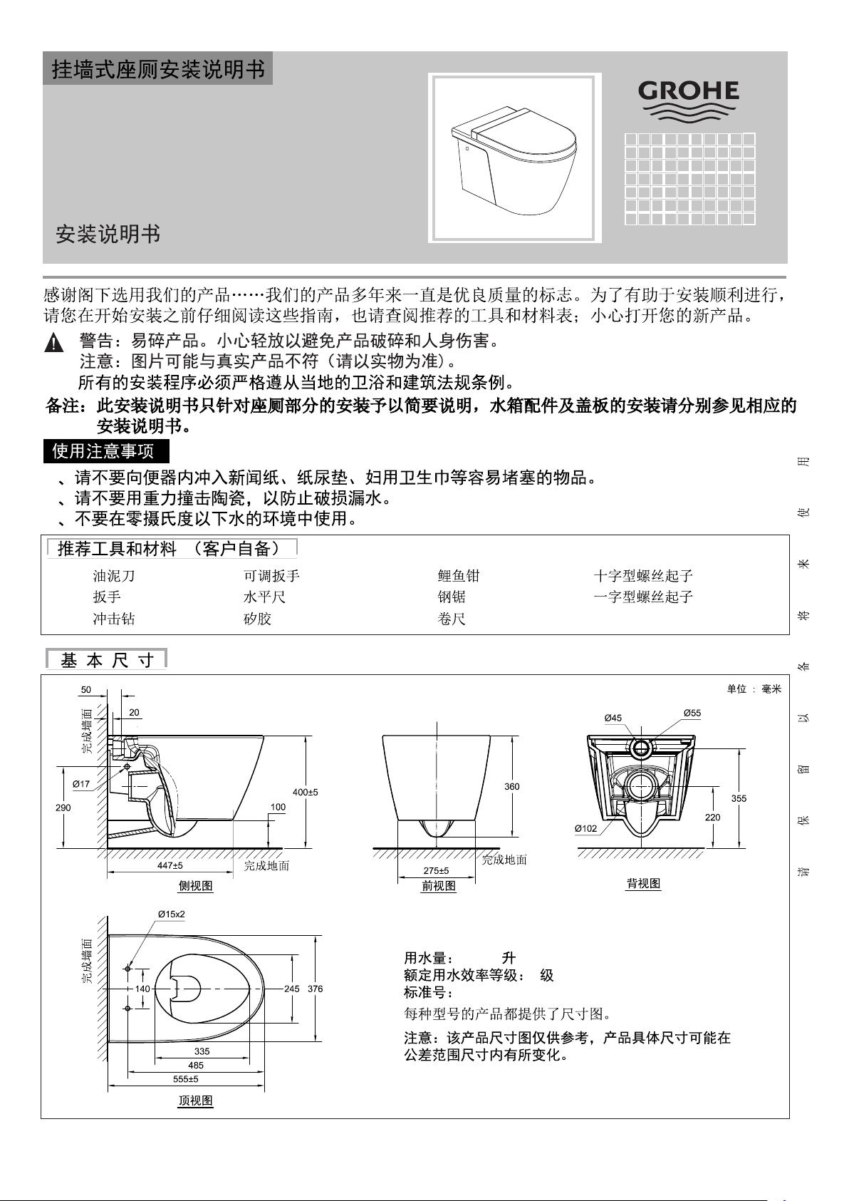
PRODUCT DIMENSIONS
50
llaw dehsiniF
20
17
290
Finished Floor
447
5
15x2
100
SIDE VIEW
400
Unit : mm
45
5
Finished Floor
275
5
FRONT VIEW
360
102
BACK VIEW
55
355
220
Finished Floor
llaw dehsiniF
140
245
376
Dimension diagrams are provided for each model.
Note : dimensions are nominal and may vary within
the range of manufacturing tolerances.
555
335
485
5
TOP VIEW
- 1 -
Nov.15
Rev.01
Page 14
CONCEALED TANK INSTALLATION
1
Tank Installation
Finished wall
Install the concealed tank and tank fitting
according to it’s installation manual.
2
Wall Finishing Preparation
Finished wall
180 mm.
Fixing bolts
Cover for water outlet
Cover for
water inlet
Before finishing the wall, install the fixing bolts first.
Cover the water inlet & outlet to avoid debris of
getting in.
3
Wall Bracket Installation
Install the wall bracket set according to it’s
installation manual.
CUTTING THE CONNECTOR AND THE WASTE PIPE
A
B
L
B
A
L
3 mm.
L
L
- 2 -
Nov.15
Rev.01
Page 15
4
Connectors Installation
Apply PVC solvent cement (not supplied) evenly inside
the outlet hole, then insert the plastic outlet connector.
Insert the water supply pipe into the water supply line
5
Fixing the Toilet
PVC
from the tank.
6
Push Button Installation
Push button
Install the toilet and check the levelness side to side,
tighten the bolts to fix the toilet as shown, then cover
with the bolt caps.
7
Installation Finishing
Silicone
Install the push button according to installation
manual of concealed tank.
Apply a silicone putty along the intersecting edge of
the toilet base, ensuring a complete seal. (Silicone
not supplied in the packaging) Install the seat & cover
according to seat & cover installation manual.
- 3 -
Nov.15
Rev.01
Page 16
INSTALLATION WITH FLUSH VALVE SENSOR
1
Installation of the “ L ” Bracket
45
102
Finished floor
55
355
220
Suggested Dimension
*
50
290
Finished floor
llaw dehsiniF
120
BACK VIEW
2
Installation of the Sensor
120-130 mm.
3.1 Cutting and chamfer 3.2 Applying PVC cement solvent
4 5
Bracket Set Installation
120
3.3 Install the connector as shown.
Fixing the Toilet
50-55 mm.
70-75 mm.
Unit : mm.
20 mm.
355 mm.
220 mm.
Finished floor
Install the wall bracket set according to it’s
installation manual.
Install the toilet and check the levelness side to side,
tighten the bolts to fix the toilet as shown, then cover
with the bolt caps.
- 4 -
Nov.15
Rev.01
Page 17
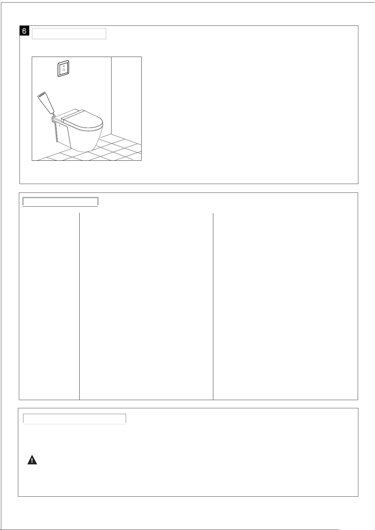
6
Installation Finishing
Apply a silicone putty along the intersecting edge of
Silicone
TROUBLE SHOOTING GUIDE
Problem
1. Poor flushing action
2. Water won’t stop
running
3. Water supply hose
leaks
the toilet base, ensuring a complete seal. (Silicone
not supplied in the packaging) Install the seat & cover
according to seat & cover installation manual.
Possible Cause
a. Water level in tank is below prescribe level.
b. Flush valve mechanism in tank closes too quickly
or dose not open.
c. Flush handle or button needs replacing.
d. Water pressure is too low.
e. Partially clogged trapway and / or drainpipe.
f. Cleanser used in tank deposits residue.
g. No air vent.
a. Water level in tank is higher than overflow pipe.
b. Turn off the water supply. If water continues to
flow into the bowl the flush valve seat and / or
rubber seal disk are worn or deformed.
c. Turn off the water supply valve. If water continues.
to flow into the bowl until the water level falls to
the level of the overflow pipe, sand or debris may
be clogged in the water control mechanism.
d. Flush valve string is too tight, holding the flush
valve open.
e. Push button needs replacing.
a. Improper installation
b. Water pressure is too high.
a. Water
To Correct
a. Set to prescribed level.
b. Make sure there are no any material stuck to outlet
components.
c. Replace.
d. Normal water supply pressure must be at least 20 psi.
e. Use a plunger or toilet auger to unclog.
f. Clean out tank and cease using the cleanser.
g. Install air vent per instructions.
a. Adjust the cylinder to maintain the water at the
prescribed level.
b. Replace seat, rubber seal disk, or complete
assembly, as needed.
c. Shut off water supply valve. Remove top cap
of water control. Clean and reassemble, or
replace plunger.
d. Replace flush valve unit.
e. Replace push button.
a. Reinstall, according to instructions.
b. Water pressure must not exceed 80 psi.
CARE AND MAINTENANCE
Do not use harsh abrasives or caustic cleanser. A mild detergent, warm water, and a soft cloth will remove normal
dirt and soap accumulations from fittings and surfaces. Rinse thoroughly after cleaning and polish with a soft dry cloth
to restore original luster of material.
Notice
Do not use cleansers in tank. Products containing chlorine(calcium hydrochlorite) can seriously damage fitings in the
tank. This damage can cause leakage and property damage. GROHE shall not be responsible or liable for any tank
fitting damage caused by the use of cleansers containing chlorine (calcium hydrochlorite)
Nov.15
- 5 -
Rev.01
Page 18
D
D
+
49 5
impre
A
A
+43 1 68060
AUS
AUS
Argent
+(02) 8394 5 800
Argent
Argent
+(03) 9682 1 231
B
+32 16 230660
3989
71
ssum
@grohe.de
Sydney
Melbourne
333
BG
359 2 9719959
+
CAU
+99 412 497 0 9 7 4
CDN
+1 888 6447643
CH
CH
+41 448777300
CN
+86 21 63758878
CY
+357 22 465200
CZ
+420 277 0 04 1 90
DK
+45 44 656800
E
+34 93 3368850
EST
+372 6616354
F
+33 1 49972900
FIN
FIN
+358 10 8201100
GB
+44 871 200 3 414
GR
+30 210 2712908
H
+36 1 238 8045
HK
+852 2969 7 067
I
+39 2 9594 01
IND
+91 124 4933000
IS
+354 515 4 000
J
+81 3 32989730
KZ
+7 727 311 0 7 3 9
LT
+372 6616354
LV
+372 6616354
MAL
+1 800 80 6570
info-singapore@grohe.com
N
+47 22 072070
NL
+31 79 3680133
NZ
+09/373 4 324
P
+351 234 529620
PL
+48 22 5432640
RI
+62 2 1 2 358 47 51
RO
+40 2 1 2 125050
ROK
+82 2 559 0790
RP
+63 2 8041617
RUS
+7 495 9819510
S
+46 771 141314
SGP
+65 6 7385585
SK
+420 277 0 04 1 90
T
+66 2610 3 685
TR
+90 216 441 2 3 7 0
GroheT [email protected]
UA
+38 44 5375273
USA
+1 800 4447643
VN
+84 8 5413 6 840
AL
BiH
ME MK SLO
+385 1 2911470
Eastern Mediterranean,
Middle East - Africa
Area Sales Office:
+357 22 465200
IR
+971 4 3318070
Far East Area Sales Office:
+65 6311 3 600
OM
HR
KS
SRB
UAE YEM
www.grohe.com
2014/ 03/21
Page 19
39321000
99.0575.031/ECN 235920/11.15
1
2
3
- 1 -
3/4.5
1
GB25502-2010
Nov.15
Rev.01
Page 20
1
2
180 毫米
3
- 2 -
Nov.15
Rev.01
Page 21
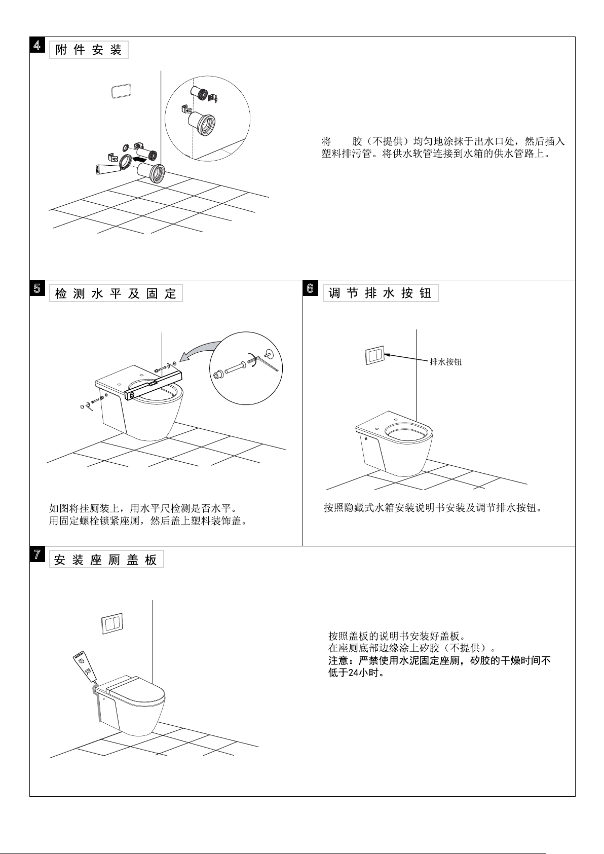
4
PVC
PVC胶
5
6
7
- 3 -
Nov.15
Rev.01
Page 22
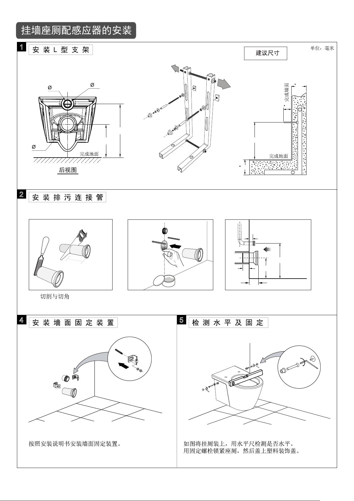
1
120
45
55
220
355
290
120
120
50
2
20毫米
120~130毫米
3.1
3.2 PVC胶的粘接 3.3 如图所示安装接头
4 5
50~55
毫米
355毫米
220毫米
完成地面
70~75毫米
- 4 -
Nov.15
Rev.01
Page 23
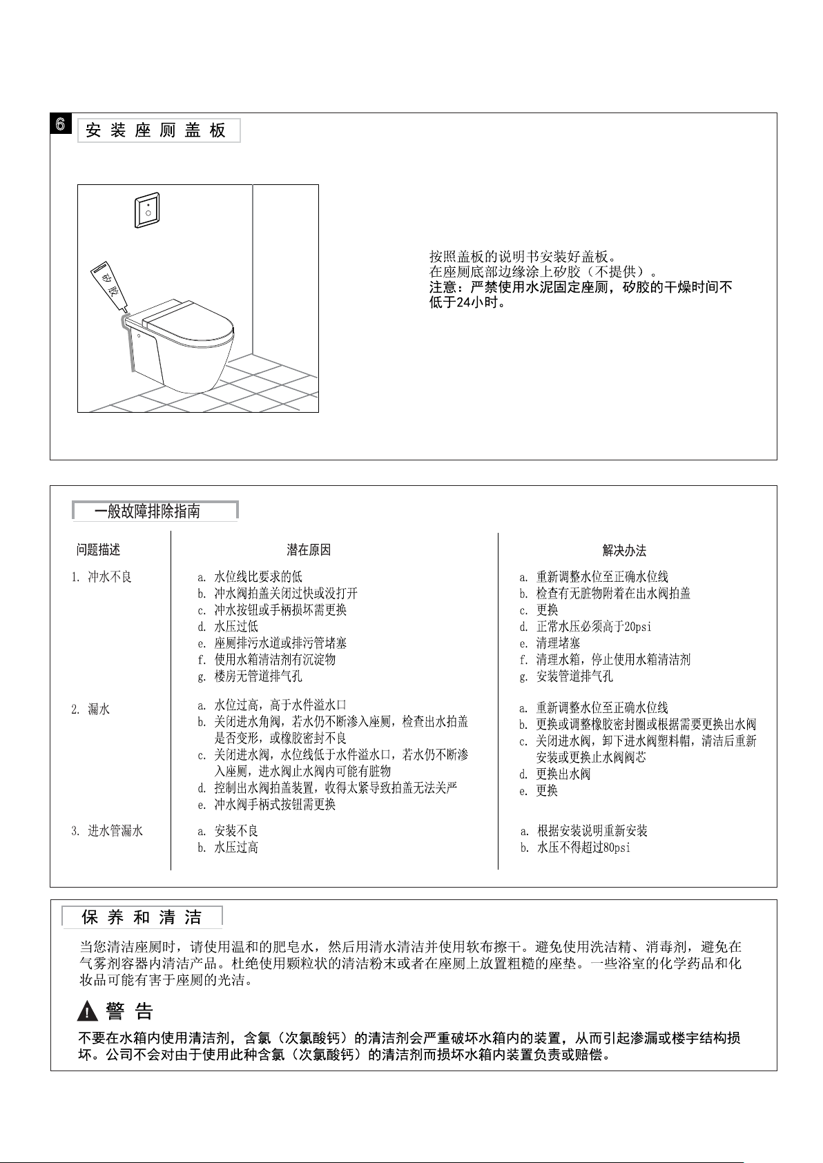
6
- 5 -
Nov.15
Rev.01
Page 24
D
D
+
49 5
impre
A
A
+43 1 68060
AUS
AUS
Argent
+(02) 8394 5 800
Argent
Argent
+(03) 9682 1 231
B
+32 16 230660
3989
71
ssum
@grohe.de
Sydney
Melbourne
333
BG
359 2 9719959
+
CAU
+99 412 497 0 9 7 4
CDN
+1 888 6447643
CH
CH
+41 448777300
CN
+86 21 63758878
CY
+357 22 465200
CZ
+420 277 0 04 1 90
DK
+45 44 656800
E
+34 93 3368850
EST
+372 6616354
F
+33 1 49972900
FIN
FIN
+358 10 8201100
GB
+44 871 200 3 414
GR
+30 210 2712908
H
+36 1 238 8045
HK
+852 2969 7 067
I
+39 2 9594 01
IND
+91 124 4933000
IS
+354 515 4 000
J
+81 3 32989730
KZ
+7 727 311 0 7 3 9
LT
+372 6616354
LV
+372 6616354
MAL
+1 800 80 6570
info-singapore@grohe.com
N
+47 22 072070
NL
+31 79 3680133
NZ
+09/373 4 324
P
+351 234 529620
PL
+48 22 5432640
RI
+62 2 1 2 358 47 51
RO
+40 2 1 2 125050
ROK
+82 2 559 0790
RP
+63 2 8041617
RUS
+7 495 9819510
S
+46 771 141314
SGP
+65 6 7385585
SK
+420 277 0 04 1 90
T
+66 2610 3 685
TR
+90 216 441 2 3 7 0
GroheT [email protected]
UA
+38 44 5375273
USA
+1 800 4447643
VN
+84 8 5413 6 840
AL
BiH
ME MK SLO
+385 1 2911470
Eastern Mediterranean,
Middle East - Africa
Area Sales Office:
+357 22 465200
IR
+971 4 3318070
Far East Area Sales Office:
+65 6311 3 600
OM
HR
KS
SRB
UAE YEM
www.grohe.com
2014/ 03/21
 Loading...