

Grohe 35500000 Service Manual

D
NL
PL
P
BG
CN
GB
S
UAE
TR
EST
UA
F
DK
GR
SK
LV
RUS
E
N
CZ
SLO
LT
I
FIN
H
HR
RO
35 500
D
NL
PL
P
BG
CN
GB
S
UAE
TR
EST
RUS
F
DK
GR
SK
LV
RUS
E
N
CZ
SLO
LT
I
FIN
H
HR
RO
RAPIDO T
DESIGN + ENGINEERING
GROHE GERMANY
96.076.231/ÄM 237340/07.16
www.grohe.com
.....1
.....1
.....2
.....2
.....3
.....3
.....4
.....4
.....5
.....5
.....6
......6
.....7
......7
.....8
......8
.....9
......9
...10
....10
.....11
.....11
.....12
.....12
.....13
.....13
.....14
.....14
.....15
.....15
.....16
.....16
.....17
.....17
.....18
.....18
.....19
.....19
.....20
.....20
.....21
.....21
.....22
.....22
.....23
.....23
.....24
.....24
.....25
.....25
.....26
.....26
.....27
.....27
.....28
.....28
Bitte diese Anleitung an den Benutzer der Armatur weitergeben!
Please pass these instructions on to the end user of the fitting.
S.v.p remettre cette instruction à l'utilisateur de la robinetterie!
I

1
B
1.
B1
2.
12mm
C
C
A
2
3
C
1
A
12mm
8
m
m
D
E
4F5
E
D
8
m
m
6
7
D
G
H
I
8mm
8
J
27mm
9
K
K1
K2
10
11
II

D
Anwendungsbereich
Betrieb ist möglich mit:
• Druckspeichern
• Thermisch/Hydraulisch gesteuerten Durchlauferhitzern
Der Betrieb mit drucklosen Speichern
(offenen Warmwasserbereitern) ist nicht möglich!
Verwendung als:
• Wanneninstallation/Brauseninstallation/Zentralinstallation
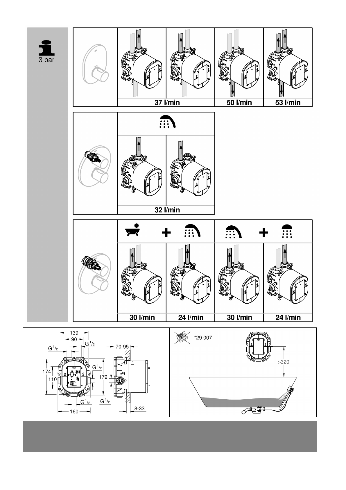
Alle Thermostate werden im Werk bei einem beidseitigen
Fließdruck von 3 bar justiert.
Bei Montage als Zentralthermostat können an den
Entnahmestellen Mischbatterien installiert werden. In diesem
Falle liefert die Thermostat-Batterie temperiertes Wasser
und es kann kaltes Wasser zugemischt werden.
Ein zusätzliches Absperrorgan ist nur notwendig,
wenn weitere Zapfstellen über freibleibende Abgänge
angeschlossen werden.
Technische Daten
• Fließdruck
- Mindestfließdruck ohne
nachgeschaltete Widerstände 0,5 bar
- Mindestfließdruck mit
nachgeschaltete Widerstände 1 bar
- Empfohlen 1 - 5 bar
• Betriebsdruck max 10 bar
• Prüfdruck 16 bar
Zur Einhaltung der Geräuschwerte nach DIN 4109 ist bei
Ruhedrücken über 5 bar ein Druckminderer einzubauen.
Höhere Druckdifferenzen zwischen Kalt- und
Warmwasseranschluss sind zu vermeiden!
• Durchfluss bei 3 bar Fließdruck
(bei gleichzeitiger Nutzung aller Abgänge) ca. 53 l/min
Bei der Installation des Abflusses beachten!
• Mindestdurchfluss 5 l/min
• Temperatur:
Warmwassereingang max. 70 °C
Zur Energieeinsparung empfohlen 60 °C
Thermische Desinfektion möglich
• Sicherheitssperre 38 °C
• Warmwassertemperatur am Versorgungsanschluss
min. 2 °C höher als Mischwassertemperatur
Achtung bei Frostgefahr
Bei Entleerung der Hausanlage sind die Thermostate
gesondert zu entleeren, da sich im Kalt- und
Warmwasseranschluss Rückflussverhinderer befinden. Bei
den Thermostaten sind die kompletten Thermostateinsätze
und die Rückflussverhinderer auszuschrauben.
Hinweis:
Bei der Kombination von Unterputzbatterien mit
Wannenfüll- und Überlaufgarnituren Folgendes beachten:
• Laut EN1717 ist eine zugelassene Sicherheitseinrichtung
vorgeschrieben. Hierzu kann ein Sonderzubehör eingesetzt
werden (siehe Ersatzteile Klappseite III, Best.-Nr.: 29 007).
• Die Sicherheitseinrichtung muss über dem Wannenrand
montiert werden, siehe Klappseite I!
Installation
Maßzeichnung auf Klappseite I beachten.
Einbau, siehe Klappseite II Abb. [1].
Unterschiedliche Einbaumöglichkeiten, siehe vorgesehene
Befestigungslöcher in Abb. [1].
Bei Installation eines GROHE Custom Shower Systems ist auf
Höhe der Markierung, siehe Detail B1, eine Ausrichtungslinie
für weitere Installationsboxen zu ziehen.
Löcher für Thermostaten sowie Schlitze für die Rohrleitungen
erstellen (siehe DIN 1053).
Thermostat mit Einbauschablone einbauen,
siehe Abb. [2] und [3].
• Die fertige Wandoberfläche muss im Bereich (A)
der Einbauschablone liegen.
• Der Warmwasseranschluss muss links,
der Kaltwasseranschluss rechts erfolgen.
Thermostat ausrichten, siehe Abb. [1].
Wasserwaage auf die Nocken (B) der Einbauschablone legen.
Rohrleitungen anschließen, siehe Abb. [2] und [3].
• Bei Einbau als Wannenbatterie muss ein beiliegender
Stopfen (C) in den freibleibenden Abgang (unten)
eingedichtet werden, siehe Abb. [2].
• Bei Einbau als Brausebatterie müssen die beiliegenden
Stopfen (C) in die freibleibenden Abgänge (oben und unten)
eingedichtet werden, siehe Abb. [2].
• Bei Einbau als Zentralbatterie müssen die beiliegenden
Stopfen (C) in die freibleibenden Abgänge (oben)
eingedichtet werden, siehe Abb. [3].
Der untere Abgang erfordert immer ein zusätzliches
Absperrorgan.
Eine Lötverbindung darf nicht vorgenommen werden, da
sie die eingebauten Rückflussverhinderer beschädigen kann.
Kalt- und Warmwasserzufuhr öffnen und
Armaturenanschlüsse auf Dichtheit prüfen.
Rapido T in Kombination mit Wannenfüll- und
Überlaufgarnitur, siehe Abb. [4] bis [6].
Wasser zur Wannenfüll- und Überlaufgarnitur während
der Installation mit beiliegenden Stopfen (F) absperren:
1. Deckel (D) abnehmen, siehe Abb. [4].
2. Verschlussstopfen (E) herausschrauben.
3. Stopfen (F) in den Abgang für Wannenfüll- und
Überlaufgarnitur einsetzen, siehe Abb. [5].
4. Verschlussstopfen (E) einschrauben, siehe Abb. [6].
5. Deckel (D) montieren.
Hinweis:
Bei Montage der Feininstallationen muss der Stopfen (F)
entfernt werden.
Rohrleitungen vor und nach der Installation gründlich
spülen(DIN 1988/DIN EN 806), siehe Abb. [7] und [8].
1. Deckel (D) abnehmen, siehe Abb. [7].
2. Kalt- und Warmwasserzufuhr schließen.
3. Verschlussschraube (G) herausschrauben.
4. Rückflussverhinderer (H) und Sieb (I) herausnehmen.
5. Spülstopfen (J) in den freien Sitz des
Rückflussverhinderers einschrauben, siehe Abb. [8].
6. Kalt- und Warmwasserzufuhr öffnen und die
Rohrleitungen durchspülen.
7. Kalt- und Warmwasserzufuhr schließen
und die Spülstopfen (J) entfernen.
8. Sieb (I) und Rückflussverhinderer (H) einsetzen,
siehe Abb. [7].
9. Verschlussschraube (G) einschrauben.
10. Kalt- und Warmwasserzufuhr öffnen.
Trägermaterial für Dichtmittel montieren,
siehe Abb. [9] und [10].
1. Dichtmittel oder Kleber auftragen, siehe Abb. [9].
2. Mittelteil (K1) des Trägermaterials (K) an den Stegen (K2)
heraustrennen.
3. Trägermaterial (K) über die Einbauschablone schieben.
4. Nochmals Dichtmittel oder Kleber auftragen, siehe Abb. [10].
Wand fertig verputzen und verfliesen, siehe Abb. [11].
Einbauschablone nicht vor der Fertiginstallation kürzen.
Ersatzteile, siehe Klappseite III (* = Sonderzubehör).
1

GB
Application
The Concealed System can be used in conjunction with:
• Pressurised storage heaters
• Thermally/hydraulically controlled instantaneous heaters
Operation with unpressurised storage heaters (displacement
water heaters) is not possible.
Use as:
• Bath installation/Shower installation/Central installation
All thermostats are adjusted in the factory at a flow pressure
of 3 bar on both sides.
If the Concealed System is installed as a central thermostat,
standard mixers can be installed at the draw-off points. In this
case, the thermostat mixer supplies hot water to which cold water
can be added.
An additional stopcock is only required if further discharge
points are to be connected via unused outlets.
Technical data
• Flow pressure
- Minimum flow pressure without
downstream resistances 0.5 bar
- Minimum flow pressure with
downstream resistances 1 bar
- Recommended 1 - 5 bar
• Max. operating pressure 10 bar
• Test pressure 16 bar
If static pressure exceeds 5 bar, a pressure
reducing valve must be fitted.
Avoid major pressure differences between
hot and cold water supply.
• Flow rate at 3 bar flow pressure (with concurrent
use of all discharge points) approx. 53 l/min
Note when installing the outlet:
• Minimum flow rate 5 l/min
• Temperature:
Hot water inlet max. 70 °C
Recommended (energy saving) 60 °C
Thermal disinfection possible
• Safety stop 38 °C
• Hot water temperature at supply connection
min. 2 °C higher than mixed water temperature
Prevention of frost damage
When the domestic water system is drained, thermostats must be
drained separately, since non-return valves are installed in the hot
and cold water connections. The complete thermostat assemblies
and non-return valves must be unscrewed and removed.
Note:
In the case of concealed shower mixers with bath filling and
overflow sets, observe the following:
• According to EN1717 an approved safety device is
stipulated. A special accessory can be used for this purpose
(see Replacement parts, fold-out page III,
Prod. no.: 29 007).
• The approved safety device must be installed above the
bathtub rim, see fold-out page I!
Installation
Installation, see fold-out page II Fig. [1].
Refer to the dimensional drawing on fold-out page I.
For different installation options, see the pre-drilled holes
in Fig. [1].
When installing a GROHE Custom Shower system, an
orientation line for further installation boxes must be drawn at
the height of the marking, see detail (B1).
Prepare the holes for the thermostatic mixer and slots
for the pipes.
Install the thermostat using the fitting template,
see Figs. [2] and [3].
• The finished surface of the wall must lie within the area (A)
of the fitting template.
• The hot water supply must be connected on the left and the
cold water supply on the right.
Align the thermostat, see Fig. [1].
Place a spirit level on the cams (B) of the fitting template.
Connect the pipes, see Figs. [2] and [3].
• When installing as bath mixer, the plug (C) provided must be
sealed in the unused outlet (bottom), see Fig. [2].
• When installing as shower mixer, the plug (C) provided must
be sealed in the unused outlets (top and bottom),
see Fig. [2].
• When installing as central mixer, the plug (C) provided must
be sealed in the unused outlet (top), see Fig. [3].
The lower discharge point always requires an additional
stopcock.
A soldered connection is not permissible, as this could
damage the built-in non-return valve.
Open the cold and hot water supply and check the fitting
connections for watertightness.
Rapido T in combination with bath filling and overflow
sets, see Fig. [4] to [6].
Stop waterflow to bath filling and overflow sets during the
installation with attached plug (F):
1. Remove cover (D), see Fig. [4].
2. Unscrew closer plug (E).
3. Fit plug (F) in the outlet for bath filling and overflow sets,
see Fig. [5].
4. Install in screw plug (E), see Fig. [6].
5. Fit cover (D).
Note:
When assembling the detailed installations, the plug (F) must
be removed.
Flush the pipes thoroughly before and after installation
(observe EN 806), see Figs. [7] and [8].
1. Remove the cover (D), see Fig.[7].
2. Close the hot and cold water supply.
3. Remove the screw plug (G).
4. Remove the non-return valve (H) and filter (I).
5. Install the flushing plugs (J) in non-return valve seat
recesses, see Fig. [8].
6. Open the hot and cold water supply and flush the pipes
thoroughly.
7. Close the hot and cold water supply and remove the
flushing plugs (J).
8. Install the filter (I) and non-return valve (H), see Fig. [7].
9. Replace the screw plug (G).
10. Open the cold and hot water supply.
Fit substrate for sealant, see Figs. [9] and [10].
1. Apply sealant or adhesive, see Fig. [9].
2. Remove the centre piece (K1) of the substrate (K) by cutting
through the tabs (K2).
3. Push the substrate (K) over the fitting template.
4. Apply sealant or adhesive again, see Fig. [10].
Plaster and tile the wall, see Fig. [11].
Do not cut the fitting template before final installation.
Replacement parts, see fold-out page III (* = special
accessories).
2

F
Domaine d’application
Utilisation possible avec
• Accumulateurs sous pression
• Chauffe-eau instantanés à contrôle thermique/hydraulique
Un fonctionnement avec des accumulateurs sans pression
(chauffe-eau à écoulement libre) n’est pas possible!
Peut être utilisé comme…
• Installation de baignoire/de douche/centrale
Tous les thermostats sont réglés en usine sur une pression
dynamique de 3 bars.
En cas de montage comme centrale thermostatique, il est
possible d’installer des mitigeurs au niveau des points de
prélèvement. Dans ce cas, le mitigeur thermostatique permet
d’obtenir de l’eau tempérée et d’y ajouter de l’eau froide.
Un robinet d’arrêt supplémentaire est nécessaire uniquement
lorsqu’un point de puisage supplémentaire est raccordé au
niveau des sorties encore libres.
Caractéristiques techniques
• Pression dynamique
- Pression dynamique minimale
sans résistance hydraulique en aval 0,5 bar
- Pression dynamique minimale
avec résistance hydraulique en aval 1 bar
- Recommandée 1 à 5 bars
• Pression de service maximale 10 bars
• Pression d’épreuve 16 bars
Installer un réducteur de pression en cas de pressions
statiques supérieures à 5 bars.
Eviter les différences importantes de pression entre
les raccordements d’eau chaude et d’eau froide!
• Débit à une pression dynamique de 3 bars
(en cas d’utilisation simultanée
de toutes les sorties) env. 53 l/min
Précautions à prendre lors de l’installation
de l’écoulement!
• Débit minimal 5 l/min
• Température
Entrée d’eau chaude 70 °C maxi.
Recommandée pour une économie d’énergie 60 °C
Désinfection thermique possible
• Butée de sécurité 38 °C
• Température de l’eau chaude au raccord d’alimentation
au moins 2 °C de plus que la température de l’eau mitigée
Attention en cas de risque de gel
Lors du vidage de l’installation principale, vider les thermostats
séparément étant donné que les raccordements d’eau froide
et d’eau chaude sont équipés de clapets anti-retour. Sur les
thermostats, déposer les clapets anti-retour et les éléments
thermostatiques complets.
Remarque:
Avec la combinaison de robinetterie encastrée avec ensemble
de remplissage et de trop-plein, respecter ce qui suit:
• Selon EN1717, la pose d’un dispositif de sécurité autorisé
est obligatoire. Il est possible alors d’utiliser un accessoire
spécial (voir Pièces de rechange, volet III réf. 29 007).
• Le dispositif de sécurité doit être monté au-dessus du
rebord de la baignoire, voir volet I!
Installation
Montage, voir volet II, fig. [1].
Tenir compte de la cote du schéma sur le volet I.
Différentes possibilités de montage, voir les trous de montage
correspondants dans la fig. [1].
Lors de l’installation d’un système GROHE Custom Shower,
tirer un trait d’alignement à hauteur du repère, voir détail (B1),
pour d’autres boîtes d’installation.
Préparer des réservations pour le thermostat et des saignées
pour la tuyauterie.
Poser le thermostat avec le gabarit, voir fig. [2] et [3].
• Le mur fini doit affleurer dans la zone (A) du gabarit
de montage.
• Le raccordement d’eau chaude doit être effectué à gauche,
celui d’eau froide à droite.
Aligner le thermostat, voir fig. [1].
Placer un niveau à bulle d’air sur l’ergot (B) du gabarit
de montage.
Raccorder la tuyauterie, voir fig. [2] et [3].
• En cas de montage d’une robinetterie de baignoire,
fermer la sortie libre (en bas) avec le bouchon fourni (C),
voir fig. [2].
• En cas de montage d’une robinetterie de douche, fermer
les sorties libres (en bas et en haut) avec les bouchons
fournis (C), voir fig. [2].
• En cas de montage d’une robinetterie centrale, fermer
les sorties libres (en haut) avec les bouchons fournis (C),
voir fig. [3].
La sortie du bas nécessite toujours une fermeture
supplémentaire.
Il est fortement déconseillé de procéder à une soudure
des tuyauteries et du boîtier par brasage, pour ne pas
endommager les clapets anti-retour.
Ouvrir l’arrivée d’eau froide et d’eau chaude et vérifier
l’étanchéité des raccords de robinetterie.
Rapido T combiné avec un ensemble de remplissage
et de trop-plein, voir fig. [4] à [6].
Fermer les arrivées d’eau de l’ensemble de remplissage
et de trop-plein avec les bouchons fournis (F) pendant
l’installation.
1. Retirer le capot (D), voir fig. [4].
2. Dévisser le bouchon fileté (E).
3. Insérer le bouchon (F) dans la sortie pour ensemble
de remplissage et de trop-plein, voir fig. [5].
4. Visser le bouchon (E), voir fig. [6].
5. Monter le capot (D).
Remarque:
Penser à enlever le bouchon (F) lors de l’installation finale.
Bien rincer les canalisations avant et après l’installation
(respecter la norme EN 806), voir fig. [7] et [8].
1. Retirer le capot (D), voir fig. [7].
2. Fermer l’arrivée d’eau froide et d'eau chaude.
3. Dévisser le bouchon fileté (G).
4. Démonter le clapet anti-retour (H) et le tamis (I).
5. Visser le bouchon (J) dans le siège libre du clapet
anti-retour, voir fig. [8].
6. Ouvrir l’arrivée d'eau froide et d’eau chaude
et bien purger les tuyauteries.
7. Fermer les arrivées d’eau chaude et d’eau
froide et enlever les bouchons (J).
8. Insérer le tamis (I) et le clapet anti-retour (H), voir fig. [7].
9. Visser le bouchon fileté (G).
10. Ouvrir les arrivées d’eau froide et d’eau chaude.
Monter le support pour mastic, voir fig. [9] et [10].
1. Appliquer le mastic ou la colle, voir fig. [9].
2. Retirer la partie centrale (K1) du support (K) au niveau
des nervures (K2).
3. Insérer le support (K) sur le gabarit.
4. Appliquer une nouvelle fois du mastic ou de la colle,
voir fig. [10].
Enduire complètement le mur et le carreler, voir fig. [11].
Ne pas raccourcir le gabarit de montage avant
l’installation finale.
Pièces de rechange, voir volet III (* = accessoires spéciaux).
3

E
Campo de aplicación
Es posible el funcionamiento con:
• Acumuladores a presión
• Calentadores instantáneos con control térmico/hidráulico
No es posible el funcionamiento con acumuladores
sin presión (calentadores de agua sin presión).
Aplicación para:
• Instalación de bañera/Instalación de ducha/Instalación central
Todos los termostatos se ajustan en fábrica a una presión
de trabajo de 3 bares en ambas acometidas.
Cuando se utiliza este modelo como termostato central,
se pueden instalar mezcladores en los puntos de consumo.
En este caso, la batería termostática suministra agua caliente
a la que se puede mezclar agua fría.
Solamente es necesaria una llave de paso adicional cuando
se conecten otras tomas de agua mediante salidas libres.
Datos técnicos
• Presión de trabajo
- Presión mínima de trabajo sin
resistencias postacopladas 0,5 bares
- Presión mínima de trabajo con
resistencias postacopladas 1 bar
- Recomendado 1 - 5 bares
• Presión de utilización máx. 10 bares
• Presión de verificación 16 bares
Si la presión en reposo es superior a 5 bares,
hay que instalar un reductor de presión.
¡Deberán evitarse diferencias de presión importantes
entre las acometidas del agua fría y del agua caliente!
• Caudal para una presión de trabajo de 3 bares
(en caso de utilización simultánea
de todas las salidas) aprox. 53 l/min
Puntos a tener en cuenta durante la instalación
del desagüe
• Caudal mínimo 5 l/min
• Temperatura:
Entrada del agua caliente máx. 70 °C
Recomendada para ahorrar energía 60 °C
Desinfección térmica posible
• Cierre de seguridad 38 °C
• Temperatura del agua caliente en la acometida mín. 2 °C
superior a la temperatura del agua mezclada
Atención en caso de peligro de helada
Al vaciar la instalación de la casa los termostatos deberán
vaciarse aparte, pues en las acometidas del agua fría y del agua
caliente hay válvulas antirretorno. Deberán desenroscarse todos
los componentes de los termostatos junto con las válvulas
antirretorno.
Nota:
En caso de una combinación de baterías empotrables y juegos
para llenado y rebose de bañeras, tenga en cuenta lo siguiente:
• Según la normativa EN1717 es necesario disponer de un
dispositivo de seguridad autorizado. Para ello se puede utilizar
un accesorio especial (véase Piezas de recambio en la página
desplegable III, núm. de pedido: 29 007).
• El dispositivo de seguridad debe montarse sobre el borde de la
bañera, véase la página desplegable I.
Instalación
Montaje, véase la página desplegable II, fig. [1].
Respetar el croquis de la página desplegable I.
Diferentes posibilidades de montaje, véanse los orificios
de fijación previstos en la fig. [1].
Al instalar un sistema GROHE Custom Shower, hay que tender
una línea de alineamiento a la altura de la marca (véase el
detalle (B1)) para otras cajas de instalación.
Hacer los agujeros para los termostatos así como las rozas
para las tuberías.
Montar el termostato con ayuda de la plantilla de montaje,
véanse las figs. [2] y [3].
• La superficie de pared acabada debe encontrarse
en la zona (A) de la plantilla de montaje.
• La acometida del agua caliente debe estar a la izquierda;
la acometida del agua fría debe estar a la derecha.
Alinear el termostato, véase la fig. [1].
Colocar un nivel de burbuja en los tetones (B) del patrón
de montaje.
Conectar las tuberías, véanse las figs. [2] y [3].
• En caso del montaje como batería de bañera, deberá
enroscarse herméticamente uno de los tapones adjuntos (C)
en la salida que queda libre (abajo), véase la fig. [2].
• En caso del montaje como batería de ducha, deberán
enroscarse herméticamente los tapones adjuntos (C) en las
salidas que quedan libres (arriba y abajo), véase la fig. [2].
• En caso del montaje como batería central, deberán enroscarse
herméticamente los tapones adjuntos (C) en las salidas que
quedan libres (arriba), véase la fig. [3].
La salida inferior siempre requiere de una llave
de paso adicional.
No es posible realizar una conexión por soldadura,
pues ésta podría dañar las válvulas antirretorno.
¡Abrir las llaves de paso del agua fría y del agua
caliente y comprobar la estanqueidad de las conexiones
de la grifería!
Rapido T en combinación con juego para llenado y rebose
de bañeras, véanse las figs. [4] a [6].
Durante la instalación, cerrar las tuberías de agua hacia el juego
para llenado y rebose de bañeras mediante el tapón (F) adjunto:
1. Extraer la tapa (D), véase la fig. [4].
2. Desenroscar el tapón roscado (E).
3. Colocar el tapón (F) en la salida del juego para llenado
y rebose de bañeras, véase la fig. [5].
4. Enroscar el tapón roscado (E), véase la fig. [6].
5. Montar la tapa (D).
Nota:
Durante el montaje de las instalaciones de acabado
deberá quitarse el tapón (F).
¡Purgar a fondo el sistema de tuberías antes y después de la
instalación (tener en cuenta EN 806), véanse las figs. [7] y [8].
1. Extraer la tapa (D), véase la fig. [7].
2. Cerrar las llaves de paso del agua fría y del agua caliente.
3. Desenroscar el tapón roscado (G).
4. Extraer la válvula antirretorno (H) y el tamiz (I).
5. Enroscar los tapones de purga (J) en el asiento libre
de la válvula antirretorno, véase la fig. [8].
6. Abrir las llaves de paso del agua fría y del agua caliente
y purgar a fondo las tuberías.
7. Cerrar las llaves de paso del agua fría y del agua caliente
y quitar los tapones de purga (J).
8. Colocar el tamiz (I) y la válvula antirretorno (H),
véase la fig.[7].
9. Enroscar el tapón roscado (G).
10. Abrir las llaves de paso del agua fría y del agua caliente.
Montar el material de base para el impermeabilizante,
véanse las figs. [9] y [10].
1. Aplicar el impermeabilizante o el adhesivo, véase la fig. [9].
2. Separar la parte central (K1) del material de base (K)
por las almas (K2).
3. Desplazar el material de base (K) sobre la plantilla de montaje.
4. Aplicar nuevamente el impermeabilizante o el adhesivo,
véase la fig. [10].
Enlucir por completo la pared y alicatarla, véase la fig. [11].
No acortar la plantilla de montaje antes de proceder
a la instalación de acabado.
Piezas de recambio, véase la página desplegable III
(* = accesorios especiales).
4

I
Gamma di applicazioni
Il funzionamento è possibile con:
• Caldaie a pressione
• Scaldabagni istantanei a regolazione termica/idraulica
Non è possibile il funzionamento con accumulatori
di acqua calda a bassa pressione (accumulatori
di acqua calda a circuito aperto).
Impiego come:
• Installazione vasca/ doccia/ centrale
Tutti i termostatici sono tarati di fabbrica a una pressione
idraulica di 3 bar sui due lati.
Quando il presente modello viene montato come termostatico
centrale, i miscelatori standard possono essere installati
sui punti di scarico. In questo caso il miscelatore con
termostatico fornisce acqua calda alla quale potrà essere
aggiunta acqua fredda. Un dispositivo addizionale di chiusura
è solo necessario se sulle uscite rimaste libere vengono
collegati altri punti di erogazione.
Dati tecnici
• Pressione idraulica
- Pressione minima di portata senza resistenze 0,5 bar
- Pressione minima di portata con resistenza 1 bar
- Consigliato 1 - 5 bar
• Pressione max. d’esercizio 10 bar
• Pressione di prova 16 bar
Per pressioni statiche superiori a 5 bar si raccomanda
l’installazione di un riduttore di pressione.
Evitare grandi differenze di pressione fra i raccordi
d’acqua fredda e d’acqua calda.
• Portata a 3 bar di pressione idraulica (utilizzando
contemporaneamente tutte le uscite) ca. 53 l/min
Da osservare durante l’installazione dello scarico
• Portata minima 5 l/min
• Temperatura:
Entrata max. 70 °C
Consigliata per il risparmio di energia 60 °C
Disinfezione termica consentita
• Blocco di sicurezza 38 °C
• Temperatura dell’acqua calda sul raccordo di
alimentazione maggiore di min. 2 °C rispetto alla
temperatura dell’acqua miscelata
Avvertenze in caso di gelo
In caso di svuotamento dell’impianto domestico, è necessario
svuotare separatamente i termostatici, dato che nei raccordi
dell’acqua calda e di quella fredda vi sono dei dispositivi
anti-riflusso. In casi del genere, smontare interamente
i termoelementi e i dispositivi anti-riflusso.
Nota:
Combinando il miscelatore doccia da incasso con il set di
riempimento e di troppopieno vasca osservare quanto segue:
• La norma EN1717 prescrive un dispositivo di sicurezza
omologato. A tal fine si può impiegare un accessorio
(vedere i pezzi di ricambio, risvolto di copertina III,
n. d’ordine: 29 007).
• Il dispositivo di sicurezza deve essere montato sul bordo
della vasca, vedere il risvolto di copertina I.
Installazione
Montaggio, vedere risvolto di copertina II, fig. [1].
Rispettare le quote di installazione sul risvolto di copertina I.
Diverse possibilità di montaggio, vedere i fori di fissaggio
previsti nella fig. [1].
Nell’installazione di un sistema GROHE Custom Shower si
deve tracciare una linea di allineamento per ulteriori box
d’installazione all’altezza della marcatura, vedere
dettaglio (B1).
Creare i fori per i termostatici e le scanalature per le tubazioni.
Montare il termostatico con la dima di montaggio,
vedere figg. [2] e [3].
• La superficie della parete finita deve trovarsi nella zona (A)
della dima di montaggio.
• Raccordo dell’acqua calda a sinistra, fredda a destra.
Allineare il termostatico, vedere fig. [1].
A tale scopo collocare una livella sulle sporgenze (B)
della dima di montaggio.
Collegare le tubazioni, vedere figg. [2] e [3].
• Nel montaggio come rubinetto per vasca-doccia, il tappo
accluso (C) deve essere avvitato a tenuta sull’uscita che
resta libera (in basso), vedere fig. [2].
• Nel montaggio come miscelatore doccia, i tappi acclusi (C)
devono essere avvitati a tenuta sulle uscite che restano
libere (in alto e in basso), vedere fig. [2].
• Nel montaggio come rubinetto centrale, i tappi acclusi (C)
devono essere avvitati a tenuta sulle uscite che restano
libere (in alto), vedere fig. [3].
L’uscita inferiore ha sempre bisogno di un dispositivo
di chiusura addizionale.
I raccordi non devono essere saldati, onde evitare
il danneggiamento dei dispositivi anti-riflusso.
Aprire l’entrata dell’acqua calda e fredda e controllare
la tenuta dei raccordi dei rubinetti.
Rapido T in combinazione con il set di riempimento
e troppopieno vasca, vedere figg. da [4] a [6].
Chiudere l’acqua del set di riempimento e troppopieno
vasca durante l’installazione utilizzando i tappi acclusi (F):
1. Staccare il coperchio (D), vedere fig. [4].
2. Svitare il tappo di chiusura (E).
3. Inserire il tappo (F) nell’uscita del set di riempimento
e troppopieno vasca, vedere fig. [5].
4. Avvitare il tappo di chiusura (E), vedere fig. [6].
5. Montare il coperchio (D).
Nota:
Rimuovere il tappo (F) durante il montaggio delle
installazioni finali.
Prima e dopo l’installazione pulire a fondo il sistema di
tubazioni (osservare la norma EN 806), vedere figg. [7] e [8].
1. Staccare il coperchio (D), vedere fig. [7].
2. Chiudere l’entrata dell’acqua calda e fredda.
3. Estrarre il tappo a vite (G).
4. Estrarre il dispositivo anti-riflusso (H) e il filtro (I).
5. Avvitare il tappo di sciacquo (J) nella sede libera
del dispositivo anti-riflusso, vedere fig. [8].
6. Aprire l’entrata dell’acqua calda e fredda e sciacquare
a fondo le tubazioni.
7. Chiudere l’entrata dell’acqua calda e fredda e rimuovere
il tappo di sciacquo (J).
8. Inserire il filtro (I) e il dispositivo anti-riflusso (H),
vedere fig. [7].
9. Avvitare il tappo a vite (G).
10. Aprire l’entrata dell’acqua fredda e calda.
Montare il materiale di tenuta per il sigillante,
vedere figg. [9] e [10].
1. Applicare il sigillante o il collante, vedere fig. [9].
2. Staccare la parte centrale (K1) del materiale di tenuta (K)
sui tratteggi (K2).
3. Spostare il materiale di tenuta (K) sulla dima di montaggio.
4. Applicare ancora il sigillante o il collante, vedere fig. [10].
Rifinire la parete e applicare le piastrelle, vedere fig. [11].
Non accorciare la dima di montaggio prima del termine
dell’installazione.
Per i pezzi di ricambio, vedere il risvolto di copertina III
(* = Accessori speciali).
5

NL
Toepassingsgebied
Te gebruiken in combinatie met:
• Boilers
• Geisers/C.v.-ketels met warmwatervoorziening
Het werken met lagedrukboilers (open warmwatertoestellen)
is niet mogelijk.
Gebruik als:
• Badkuipinstallatie/Douche-installatie/Centrale installatie
Alle thermostaten worden in de fabriek met een aan beide
kanten heersende stromingsdruk van 3 bar afgesteld.
Bij montage als een centrale thermostaat kunnen aan
de aftappunten mengkranen worden geïnstalleerd. In dat
geval levert de mengkraan van de thermostaat warm water,
waaraan koud water kan worden toegevoegd.
Een extra blokkeerinrichting is alleen maar nodig als er nog
meer aftappunten boven de vrijblijvende aansluitopeningen
worden aangesloten.
Technische gegevens
• Stromingsdruk
- Minimale stromingsdruk zonder
nageschakelde weerstanden 0,5 bar
- Minimale stromingsdruk met
nageschakelde weerstanden 1 bar
- Aanbevolen 1 - 5 bar
• Max. werkdruk: 10 bar
• Testdruk 16 bar
Bij statische drukken boven 5 bar dient een
drukreduceerventiel te worden ingebouwd.
Voorkom hoge drukverschillen tussen
de koud- en warmwateraansluiting!
• Capaciteit bij 3 bar stromingsdruk (bij gelijktijdig
gebruik van alle aansluitopeningen) ca. 53 l/min
Aandachtspunten bij het installeren van de afvoer
• Minimum capaciteit 5 l/min
• Temperatuur:
Warmwateringang max. 70 °C
Ter energiebesparing aanbevolen 60 °C
Thermische desinfectie is mogelijk
• Veiligheidsblokkering 38 °C
• Warmwatertemperatuur bij de toevoeraansluiting
is min. 2 °C hoger dan de mengwatertemperatuur
Attentie bij vorst
Bij het aftappen van de waterleidinginstallatie dienen
de thermostaten apart te worden afgetapt, omdat zich in de
koud- en warmwateraansluiting terugslagkleppen bevinden.
Hierbij moeten het complete thermostaatelement en
de terugslagkleppen worden verwijderd.
Aanwijzing:
Neem bij de combinatie van overloopgarnituren met
toevoer- en overloopgarnituren het volgende in acht:
• Conform EN1717 is een goedgekeurde
veiligheidsvoorziening verplicht. Hiervoor kan een speciaal
toebehoren worden gebruikt (zie Reserveonderdelen
uitvouwbaar blad III, best.nr.: 29 007).
• De beveiligingsinrichting moet boven de wand van de
badkuip worden gemonteerd, zie uitvouwbaar blad I.
Installeren
Inbouw, zie uitvouwbaar blad II, afb. [1].
Neem de maatschets op uitvouwbaar blad I in acht.
Verschillende inbouwopties, zie reeds aangebrachte
bevestigingsgaten in afb. [1].
Bij de installatie van een GROHE Custom Shower System
moet u ter hoogte van de markering, zie detail (B1), een lijn
trekken zodat u de andere installatieboxen precies evenwijdig
aan elkaar kunt monteren.
Breng de gaten voor de thermostaten en de sleuven
voor de leidingen aan.
Thermostaat met inbouwsjabloon inbouwen,
zie afb. [2] en [3].
• Het afgewerkte wandoppervlak moet in het gebied (A)
van de inbouwsjabloon liggen.
• De warmwateraansluiting moet links,
de koudwateraansluiting rechts zijn.
Thermostaat uitlijnen, zie afb. [1].
Leg een waterpas op de nokken (B) van de inbouwsjabloon.
Sluit de leidingen aan, zie afb. [2] en [3].
• Bij inbouw als badmengkraan moet er een meegeleverde
plug (C) in de vrijblijvende afvoer (onder) worden
aangebracht, zie afb. [2].
• Bij inbouw als douchemengkraan moeten de meegeleverde
pluggen (C) in de vrijblijvende afvoeren (boven en onder)
worden aangebracht, zie afb. [2].
• Bij inbouw als centrale mengkraan moeten
de meegeleverde pluggen (C) in de vrijblijvende
afvoeren (boven) worden aangebracht, zie afb. [3].
Voor de onderste afvoer is altijd een extra afsluiter vereist.
Een soldeerverbinding is niet toegestaan, omdat deze
de ingebouwde terugslagkleppen kan beschadigen.
Open de koud- en warmwatertoevoer en controleer
de aansluitingen van de mengkraan op lekkages.
Rapido T in combinatie met toevoer- en
overloopgarnituur, zie afb. [4] t/m [6].
Blokkeer het water naar de toevoer- en overloopgarnituur
tijdens de installatie met de meegeleverde pluggen (F):
1. Verwijder het deksel (D), zie afb. [4].
2. Schroef de afsluitplug (E) los.
3. Plaats de plug (F) in de afvoer voor toevoeren overloopgarnituur, zie afb. [5].
4. Schroef de afsluitplug (E) vast, zie afb. [6].
5. Deksel (D) monteren.
Aanwijzing:
Bij het monteren van de afwerkingen moet de plug (F)
worden verwijderd.
Leidingen vóór en na het installeren grondig spoelen
(EN 806 in acht nemen), zie afb. [7] en [8].
1. Verwijder het deksel (D), zie afb. [7].
2. Sluit de koud- en warmwatertoevoer af.
3. Schroef de afsluitschroef (G) los.
4. Haal de terugslagklep (H) en de zeef (I) eruit.
5. Schroef de spoelstop (J) in de vrije zitting van
de terugslagklep, zie afb. [8].
6. Open de koud- en warmwatertoevoer en spoel
de leidingen door.
7. Sluit de koud- en warmwatertoevoer af en verwijder
de spoelstoppen (J).
8. Plaats de zeef (I) en de terugslagklep (H), zie afb. [7].
9. Schroef de afsluitschroef (G) vast.
10. Open de koud- en warmwatertoevoer.
Monteer het dragermateriaal voor het afdichtmiddel,
zie afb. [9] en [10].
1. Breng afdichtmiddel of lijm aan, zie afb. [9].
2. Verwijder het middelste gedeelte (K1) van het
dragermateriaal (K) bij de verbindingsstukken (K2).
3. Schuif het dragermateriaal (K) over de inbouwsjabloon.
4. Breng nogmaals afdichtmiddel of lijm aan, zie afb. [10].
Bepleister de muur en breng tegels aan, zie afb. [11].
Kort de inbouwsjabloon niet af voordat alles gemonteerd
en afgewerkt is.
Reserveonderdelen, zie uitvouwbaar blad III
(* = speciaal toebehoren).
6

S
Användningsområde
Drift är möjlig med:
• Tryckbehållare
• Termiskt/Hydrauliskt styrda genomströmningsberedare
Drift med lågtrycksbehållare (öppna varmvattenberedare)
är inte möjlig!
Användning som:
• Badkarsinstallation/Duschinstallation/Centralinstallation
Alla termostater är vid leveransen inställda på ett dubbelsidigt
flödestryck av 3 bar.
Vid montering som central termostat kan man installera
blandare på tappningsställena. I detta fall ger
termostatblandaren tempererat vatten som man kan blanda
med kallt vatten.
En extra spärrenhet är endast nödvändig, om ytterligare
tappningsställen ansluts via överblivna utlopp.
Tekniska data
• Flödestryck
- Minsta flödestryck utan efterkopplade motstånd 0,5 bar
- Minsta flödestryck med efterkopplade motstånd 1 bar
- Rekommenderat 1 - 5 bar
• Arbetstryck max 10 bar
• Testtryck 16 bar
En reduceringsventil ska installeras
om vilotrycket överstiger 5 bar.
Större tryckdifferenser mellan kallvatten- och
varmvattenanslutningen måste undvikas!
• Kapacitet vid 3 bar flödestryck
(vid samtidig användning av alla utlopp) ca 53 l/min
Observera vid installationen av utloppet!
• Min. kapacitet 5 l/min
• Temperatur:
Varmvattentillopp max. 70 °C
Rekommendation för energibesparing 60 °C
Termisk desinfektion kan användas
• Säkerhetsspärr 38 °C
• Varmvattentemperatur vid försörjningsanslutning
min. 2 °C högre än blandvattentemperatur
Vid risk för frost
Töms husanläggningen är det viktigt att tömma termostaterna
separat, eftersom det finns backventiler monterade
i kallvatten- och varmvattenanslutningen. På termostaterna
ska de kompletta termostatinsatserna och backventilerna
skruvas loss.
Anvisning:
Vid en kombination av inbyggnadsblandare med
vattenpåfyllning och bräddavlopp, observera följande:
• Enligt EN1717 är en godkänd säkerhetsanordning
föreskrift. Ett extra tillbehör kan då användas
(se reservdelar utvikningssida III, best.-nr: 29 007).
• Säkerhetsanordningen måste monteras över
badkarskanten, se utvikningssida I!
Installation
Montering, se utvikningssida II fig [1].
Observera måttritningen på utvikningssida I.
Olika monteringsmöjligheter, se motsvarande fästhål i fig. [1].
Vid installation av ett GROHE Custom Shower System måste
en markeringslinje ritas i höjd med markeringen, se
detaljer (B1), för ytterligare installationsboxar.
Gör hål för termostaten och slitsar för rörledningarna.
Montera termostatet med monteringsmallen,
se fig. [2] och [3].
• Väggens färdiga yta måste ligga inom
monteringsmallens område (A).
• Varmvattenanslutningen ska vara till vänster
och kallvattenanslutningen till höger.
Justera termostaten, se fig. [1].
Lägg vattenpasset på monteringsmallens kanter (B).
Anslut rörledningarna, se fig. [2] och [3].
• Vid montering som badkarsblandare, måste den
bifogade pluggen (C) placeras i det överblivna
utloppet (nedtill), se fig. [2].
• Vid montering som duschblandare, måste den
bifogade pluggen (C) placeras i de överblivna utloppen
(upptill och nedtill), se fig. [2].
• Vid montering som centralblandare, måste den bifogade
pluggen (C) placeras i de överblivna utloppen (upptill),
se fig. [3].
Det nedre utloppet kräver alltid en extra spärrenhet.
En lödning får inte genomföras, eftersom de monterade
backventilerna kan skadas.
Öppna kallvatten- och varmvattentillförseln och
kontrollera att blandarens anslutningar är täta.
Rapido T i kombination med vattenpåfyllning
och bräddavlopp, se fig. [4] till [6].
Spärra vattnet till vattenpåfyllning och bräddavlopp
under installationen med den bifogade pluggen (F):
1. Ta bort locket (D), se fig. [4].
2. Skruva loss skruvpluggen (E).
3. Sätt in pluggen (F) i utloppet för vattenpåfyllning
och bräddavlopp, se fig. [5].
4. Skruva fast skruvpluggen (E), se fig. [6].
5. Montera locket (D).
Anvisning:
Vid monteringen av fininstallationen måste pluggen (F)
tas bort.
Spola rörledningssystemet noggrant före och efter
installationen (observera EN 806), se fig. [7] och [8].
1. Ta bort locket (D), se fig. [7].
2. Stäng kallvatten- och varmvattentillförseln.
3. Skruva loss skruvpluggen (G).
4. Ta bort backventilen (H) och silen (I).
5. Skruva fast spolpluggen (J) i backventilens fria fäste,
se fig. [8].
6. Öppna kallvatten- och varmvattentillförseln och spola
rörledningarna.
7. Stäng kallvatten- och varmvattentillförseln och ta bort
spolpluggen (J).
8. Sätt in silen (I) och backventilen (H), se fig. [7].
9. Skruva fast skruvpluggen (G).
10. Öppna kallvatten- och varmvattentillförseln.
Montera fästmaterialet för tätningsmedlet,
se fig. [9] och [10].
1. För på tätningsmedel eller lim, se fig. [9].
2. Ta bort mittdelen (K1) av fästmaterialet (K)
vid flikarna (K2).
3. Skjut fästmaterialet (K) över monteringsmallen.
4. För på tätningsmedel eller lim en gång till, se fig. [10].
Putsa färdigt väggen och kakla, se fig. [11].
Korta inte av monteringsmallen före den slutliga monteringen.
Reservdelar, se utvikningssida III (* = extra tillbehör).
7
 Loading...