

Page 1
DESIGN + ENGINEERING
GROHE GERMANY
99.0270.031/ÄM 249556/02.21
www.grohe.com
Page 2
*19 001
*19 332
34mm
34mm
30mm
*19 377
22mm
30mm
*19 337
1
Page 3
1
2
2
Page 4
38 °
3
Page 5
*19 377
30mm
12mm
12mm
11
4
Page 6
34mm
*19 332
10
11
19mm
1.
2.
3.
4.
17mm
5
Page 7
GB
Safety notes
Protection against scalding
It is recommended that near points of discharge with
particular sensitivity to the outlet temperature
(hospitals, schools, nursing and retirement homes)
thermostatic devices should be installed which can limit the
water temperature to 43 °C. The product includes an
appropriate temperature end stop. It is generally
recommended that the temperature of shower-systems should
not exceed 38 °C in nurseries and specific areas of care
centres. Use Grohtherm Special thermostats with special
handle to facilitate thermal disinfection and appropriate safety
end stop. Applicable standards (e. g. EN 806-2) and technical
regulations for drinking water must be observed.
Safety and important information
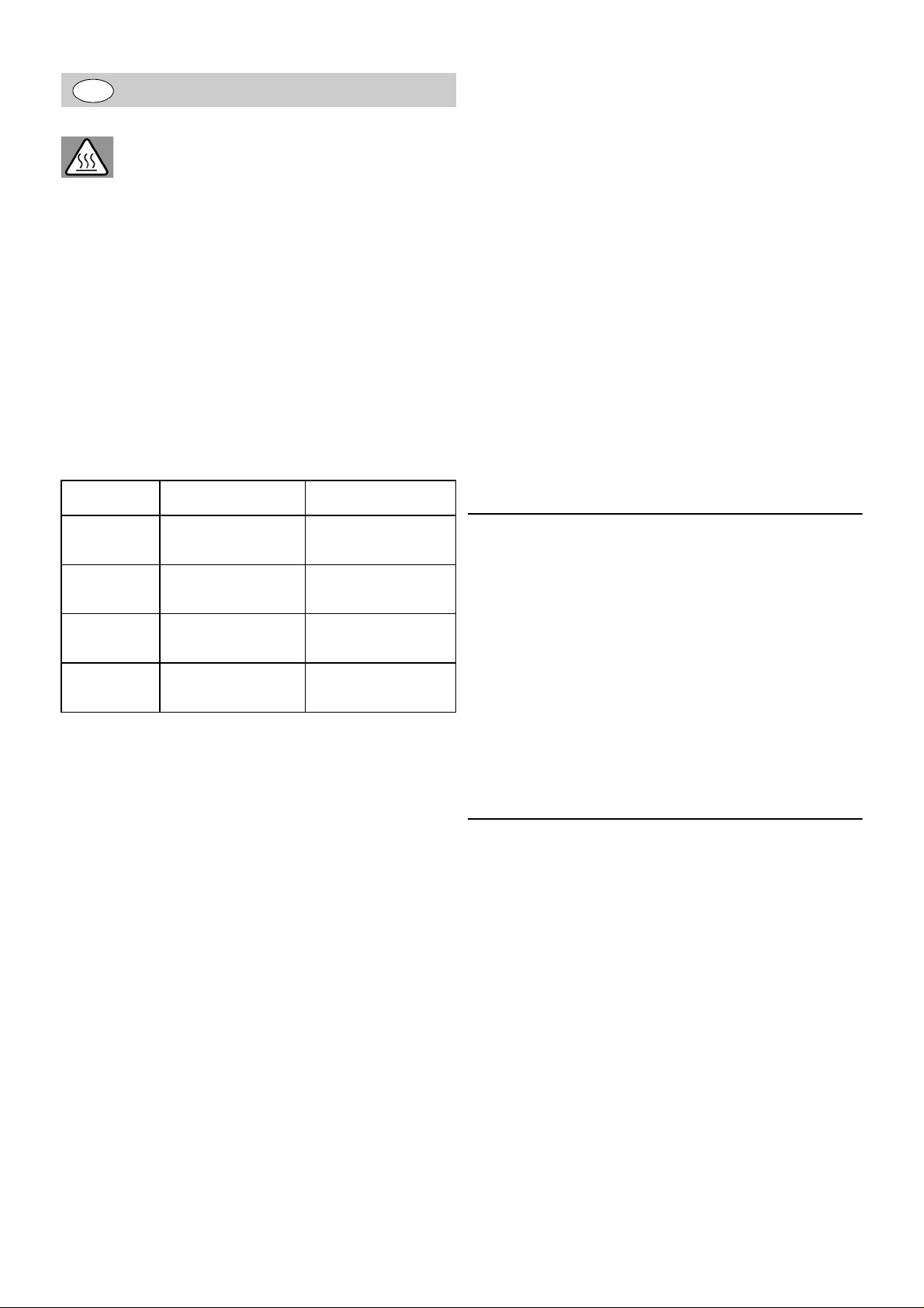
This thermostatic valve will suit supplies of:
High pressure.
Conditions of use TMV2
high pressure low pressure
It is not a safe bathing temperature for adults or children.
The British Burns Association recommends 37 to 37.5 °C as a
comfortable bathing temperature for children. In premises
covered by the Care Standards Act 2000, the maximum mixed
water outlet temperature is 43 °C.
The thermostatic mixing valve will be installed in such a
position that maintenance of the TMV and its valves and the
commissioning and testing of the TMV can be undertaken.
Requirements shall be verified against the original set
temperature results once a year.
The installation of thermostatic mixing valves must comply with
the requirements of the Water Supply (Water Fittings)
Regulations 1999.
The fitting of isolation valves is required as close as is
practicable to the water supply inlets of the thermostatic mixing
valve.
Notes
If there is a residual flow during the commissioning or the
annual verification (cold water supply isolation test), then this
is acceptable providing the temperature of the water seeping
from the valve is no more than 2°C above the de signated
maximum mixed water outlet temperature setting of the valve.
max. static
pressure
flow pressure
hot/cold
hot supplied
temperature
cold supplied
temperature
NOTE: Valves operating outside these conditions cannot be
guaranteed by the Scheme to operate as Type 2 valves.
The designation of use is high pressure tub (HP-T) and high
pressure shower (HP-S).
HP-S for 34 438, 34 557, 34 818 and 34 825
HP-S and HP-T for 34 439 and 34 821
If a water supply is fed by gravity then the supply pressure
should be verified to ensure the conditions of use are
appropriate for the valve.
Recommended outlet temperature
• 44 °C for bath fill
but:
- 41 °C for shower and washbasin
- 38 °C for bidet
The mixed water temperatures must never exceed 46°C.
equal to or less 25 °C equal to or less 25 °C
10 bar 10 bar
0,5 to 5 bar 0,1 to 1 bar
55 to 65 °C 55 to 65 °C
Application
Thermostat mixers are designed for hot water supply via
pressurised storage heaters and, utilised in this way, provide
the best temperature accuracy. With sufficient power output
(from 18 kW or 250 kcal/min), electric or gas instantaneous
heaters are also suitable.
Thermostats cannot be used in conjunction with
non-pressurised storage heaters (displacement water
heaters).
All thermostats are adjusted in the factory at a flow pressure
of 3 bar on both sides.
Should temperature deviations occur on account of special
installation conditions, the thermostat must be adapted to local
conditions (see Adjusting).
Specifications
Safety stop 38 °C
Hot water temperature at supply connection min. 2 °C higher
than mixed water temperature
Thermal desinfection possible
Minimum flow rate = 5 l/min
If static pressure exceeds 5 bar, a pressure reducing valve
must be fitted.
The maximum mixed water temperature can be 2°C above the
recommended maximum set outlet temperatures.
NOTE: 46°C is the maximum mixed water temperature from
the bath tap. The maximum temperature takes account of the
allowable temperature tolerances inherent in thermostatic
mixing valves and temperature losses in metal baths.
1
6
Page 8
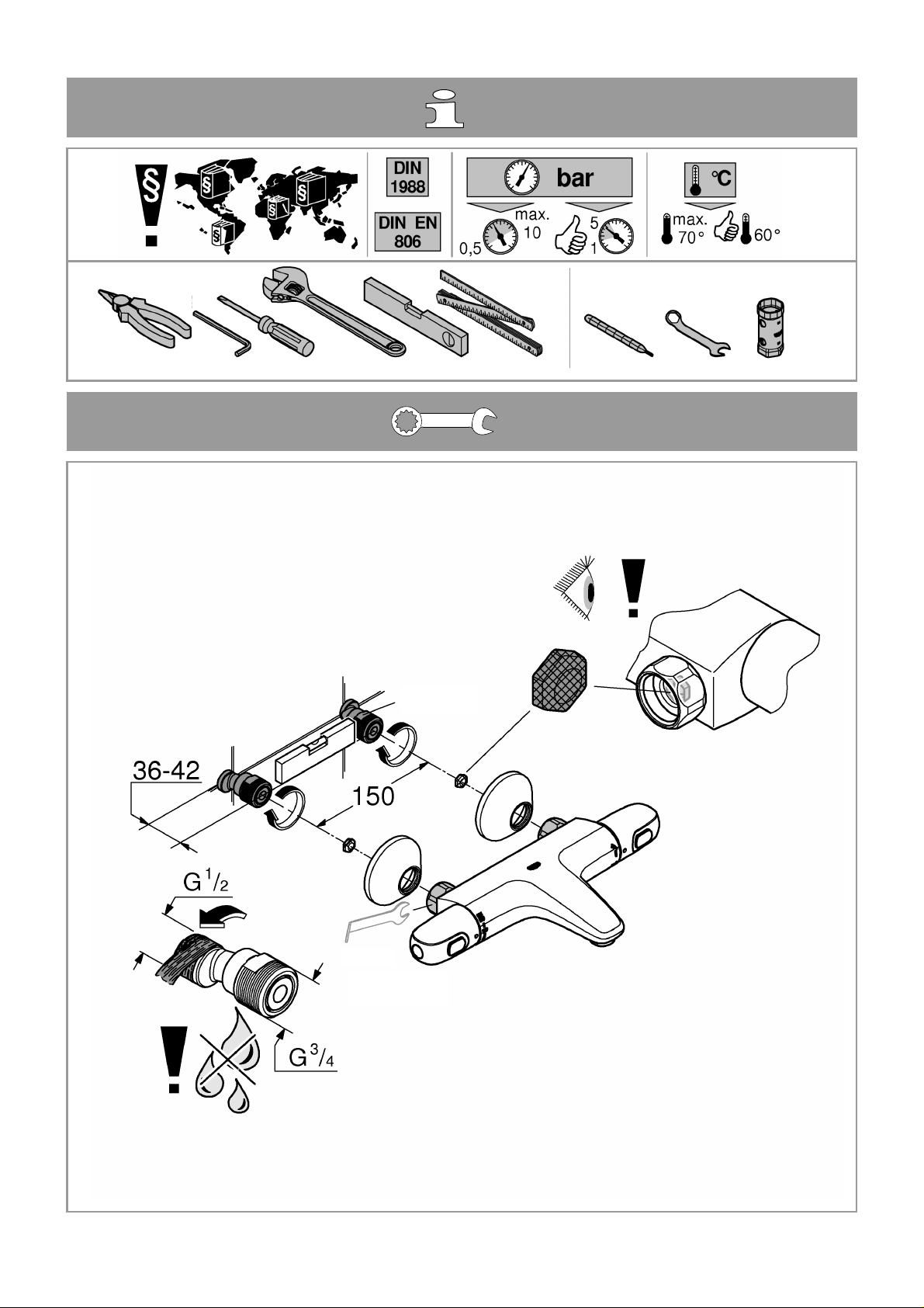
Installation
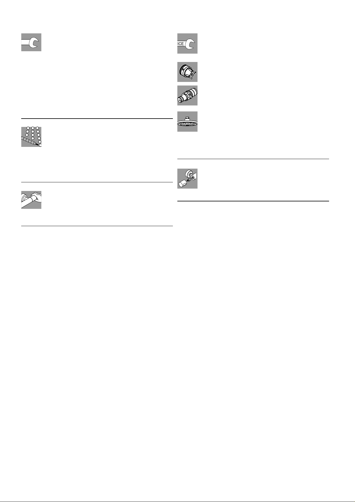
The projection can be increased by 20mm with an
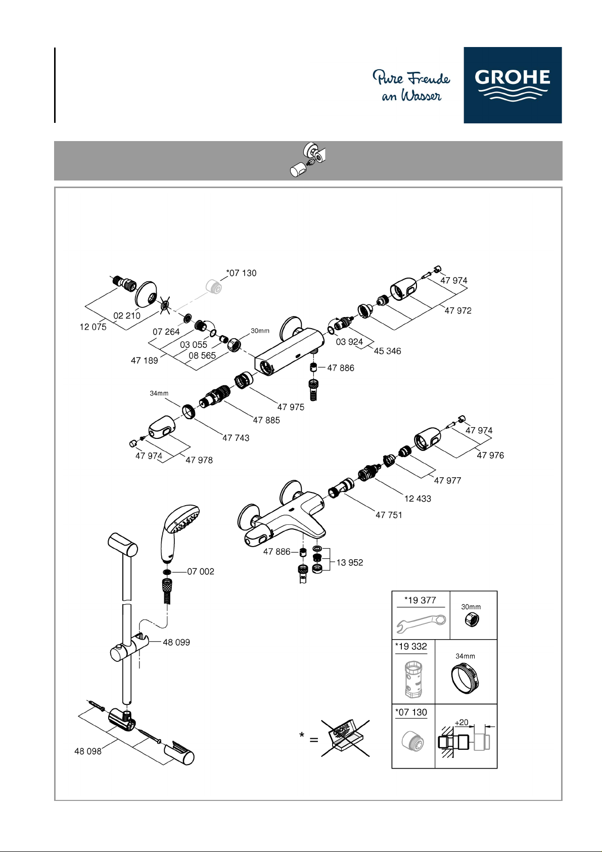
extension, see Replacement Parts, Prod.no. 07 130.
Reversed connection (hot on right - cold on left).
Replace thermostatic compact cartridge, see Replacement
parts, Prod. no.: 47 885 (1/2”).
When using this thermostatic compact cartridge, the Cool
Touch function is no longer available.
Installation of the shower rail
When installing e.g. on plasterboard walls (not solid walls) it
must be assured that an appropriate reinforcement is in place
to ensure sufficient strength.
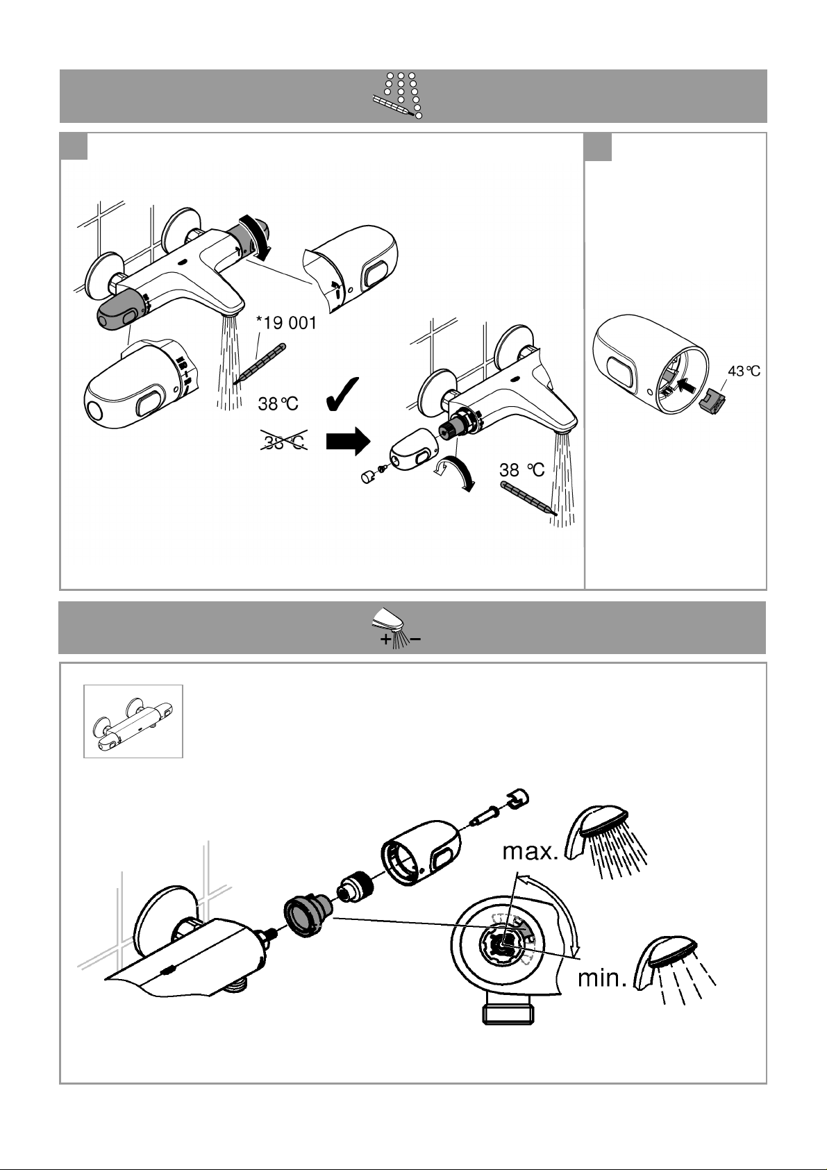
Adjusting
Temperature adjustment, see page 2 Fig. [1].
Temperature end stop
If the temperature end stop is at 43 °C, insert accompanying
temperature limiter in temperature selection handle,
see Fig. [2].
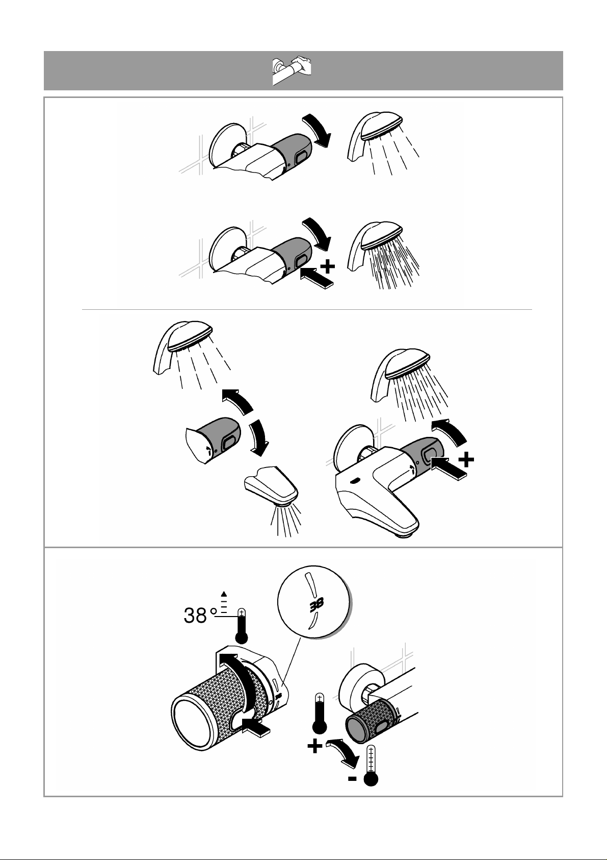
Operation
The safety stop limits the temperature range to 38 °C.
The 38 °C limit can be overridden by pressing the
button, see page 3.
Prevention of frost damage
When the domestic water system is drained, thermostat
mixers must be drained separately, since non-return valves
are installed in the hot and cold water connections. For this
purpose, the mixer must be removed from the wall.
Maintenance
Inspect and clean all parts, replace if necessary and
lubricate with special valve grease.
Shut off the hot and cold water supply.
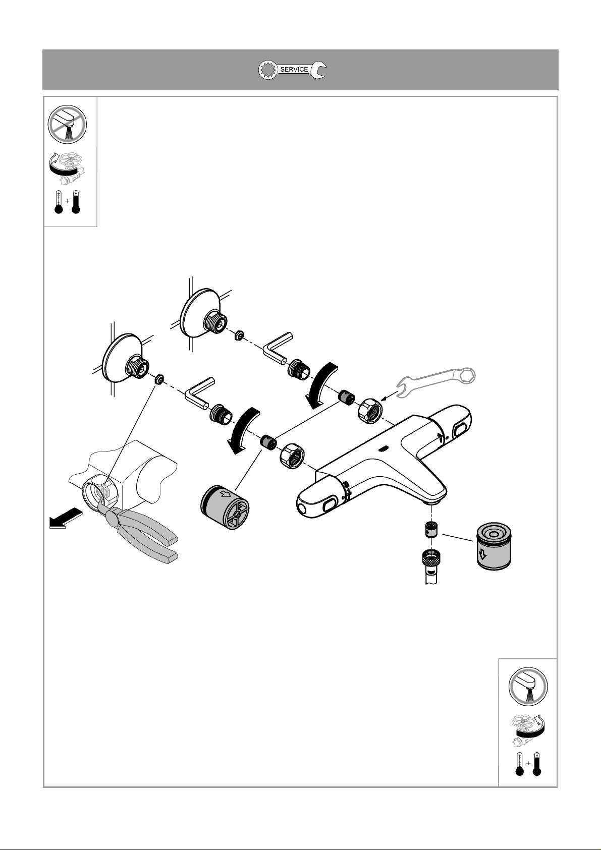
Non-return valve, see page 4.
Drain the fitting before disassembling.
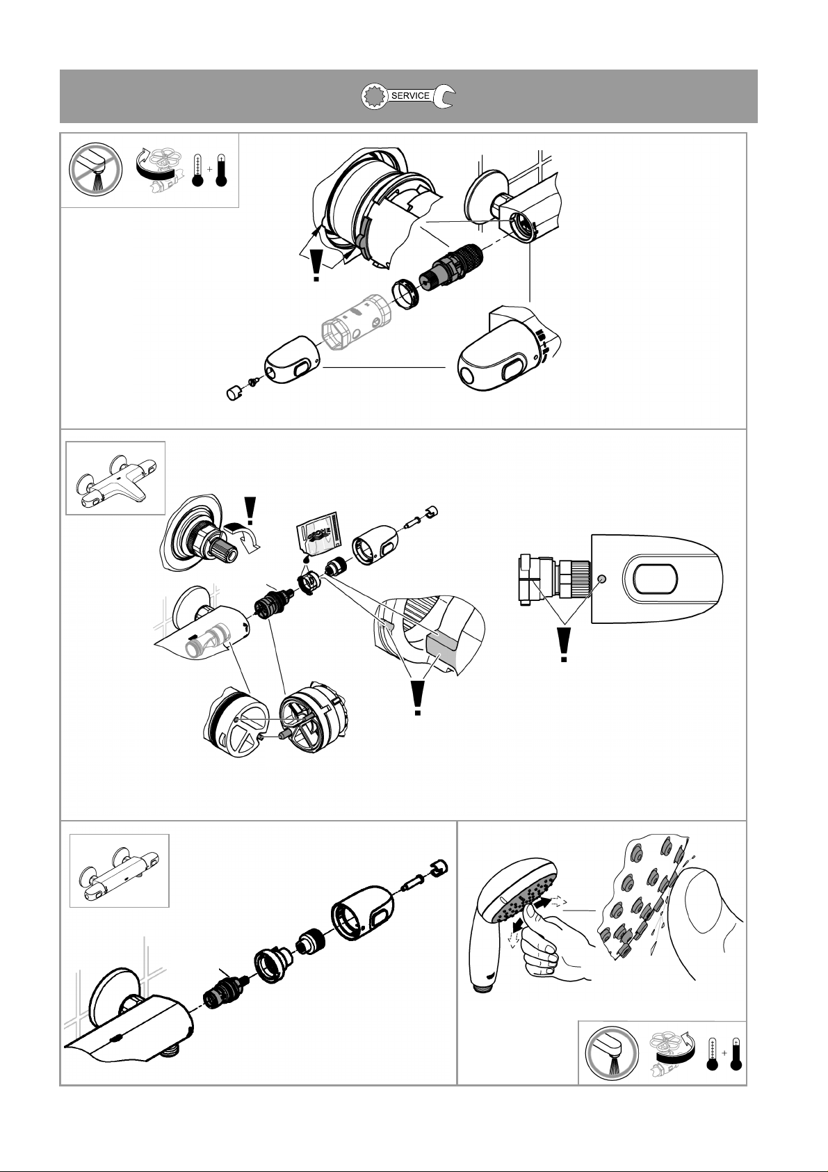
Thermostatic compact cartridge, see page 5.
Readjustment is necessary after every maintenance
operation on the thermostatic compact cartridge
(see Adjusting).
Showers, see page 5.
The function of the SpeedClean nozzles is
guaranteed for a period of five years.
Thanks to the SpeedClean nozzles, which must be
regularly cleaned, limescale deposits on the rose can be
removed by simply rubbing with the fingers.
Replacement parts
( * = special accessories).
Care
For directions on care, refer to the accompanying Care
Instructions.
1
7
Page 9
F
Consignes de sécurité
Prévention d’échaudage
Pour des points de puisage où la température de
l’eau est particulièrement critique (hôpitaux, écoles,
résidences médicalisées), il est recommandé de
systématiquement utiliser des thermostats pouvant être limités
à 43 °C. Une butée de température pe rmettant la limitation e st
incluse avec ce produit. Pour les systèmes de douche dans les
écoles maternelles et dans certaines parties de résidences
médicalisées, il est généralement recommandé de ne pas
dépasser une température de 38 °C. Utilisez ici des
thermostats Grohtherm Special avec poignée spéciale pour
l’aide à la désinfection thermique et la butée finale d e sé curité
correspondante. Respectez les normes en vigueur (par ex.
EN 806 2) ainsi que les règlementations techniques pour l’eau
potable.
Domaine d'application
Les robinetteries thermostatiques sont conçues pour fournir de
l'eau chaude avec des accumulateurs sous pression et
permettent d'obtenir une température de l'eau extrêmeme nt
précise. Si la puissance est suffisante (à partir de 18 kW,
ou 250 kcal/min), des chauffe-eau instantanés électriques ou
au gaz conviennent également.
Les thermostats ne peuvent pas être utilisés avec des
accumulateurs sans pression (chauffe-eau à écoulement
libre). Tous les thermostats sont réglés en usine sur une
pression dynamique de 3 bars. Si des différences de
température devaient apparaître, régler le thermostat en
fonction des conditions locales d'utilisation (voir Réglage).
Réglage
Réglage de la température, voir page 2 fig. [1].
Butée de température maximale
Si la butée de température maximale est réglée sur 43 °C,
mettre en place le limiteur de température joint dans la
poignée de sélection de la température, voir fig. [2].
Commande
La température est limitée à 38 °C par le verrouillage
de sécurité.
Il est possible d'aller au-delà de la limite des 38 °C et d'obtenir
une température plus élevée en appuyant sur la touche, voir
page 3.
Attention en cas de risque de gel
En cas de mise hors gel, la purge simple de l’installation n’est
pas suffisante pour protéger la robinetterie. Lors de la purge
de l’installation principale, vous devez vider le corps
thermostatique dont les raccordements d'eau froide et d'eau
chaude sont équipés de clapets anti-retour. Pour cela, ôter le
thermostat du mur.
Maintenance
Vérifier toutes les pièces, les nettoyer, les remplace
éventuel-lement et les lubrifier avec la graisse
spéciale pour robinets.
Couper l'alimentation en eau chaude et en eau froide.
Clapet anti-retour, voir page 4.
Vider la robinetterie avant le démontage.
Caractéristiques techniques
Verrouillage de sécurité 38 °C
Température de l'eau chaude au raccord d'alimentation au
moins 2 °C de plus que la température de l'eau mitigée
Désinfection thermique possible
Débit minimal = 5 l/min
Installer un réducteur de pression en cas de pressions
statiques supérieures à 5 bars.
Installation
La saillie peut être augmentée à l'aide d'une rallo nge
de 20mm, pièces de rechange,
réf. 07 130.
Raccordement inversé (chaud à droite - froid à gauche).
Remplacer la cartouche compacte de thermostat, voir pièces
de rechange, réf. 47 885 (1/2”).
Lors de l’insertion de la cartouche compacte de thermostat,
la fonction Cool Touch a été supprimée.
Montage de la barre de douche
En cas de montage sur un support souple, une plaque de
plâtre par exemple, s'assurer que des renforts ont été montés
sur le mur.
Cartouche compacte de thermostat, voir page 5.
Après tout travail de maintenance sur la cartouche
compacte de thermostat, un réglage est nécessaire
(voir Réglage).
Douche, voir page 5.
Les buses SpeedClean sont garanties 5 ans.
Les buses SpeedClean, qui doivent être nettoyées
régulièrement, permettent d'éliminer, par frottement avec les
doigts, les dépôts calcaires sur le diffuseur.
Pièces de rechange
(* = accessoires spéciaux).
Entretien
Les indications relatives à l'entretien figurent sur la notice
jointe à l'emballage.
1
8
Page 10
2020/06/09
www.grohe.com
D
A
AUS
B
&
+32 (0)2 899 3077
https://www.grohe.be/nl_be/
onze-service/contact.html
BG
&
+359 2 971 99 59
[email protected]
BR
&
0800 770 1222
[email protected]
CAU
&
+99 412 497 09 74
[email protected]
CDN
&
+1 888 6447643
[email protected]
CH
&
+41 44 877 73 00
[email protected]
CN
&
+86 4008811698
[email protected]
CZ
&
+420 277 004 193
[email protected]
DK
&
+45 44 65 68 00
[email protected]
E
&
+34 93 / 3 36 88 50
[email protected]
EST
LT
LV
&
+372 661 6354
[email protected]
F
FIN
GB
GR
H
HK
I
IND
IS
J
KZ
MAL
MX
N
NL
&
+31(0) 88-0030700
https://www.grohe.nl/nl_nl/
onze-service/contact.html
NZ
&
+64 09 573 0490
[email protected]
P
&
+351 234529620
[email protected]
PL
&
+48 (22) 5432640
[email protected]
RI
&
0800-1-047-643
customercare[email protected]
RO
&
+40 021 212 50 50
[email protected]
ROK
&
+82 2 1588 5903
[email protected]
RP
RUS
&
8 800 200 00 49
[email protected]
S
&
+46 771 14 13 14
[email protected]
SGP
RC
&
+65 6311 3611
[email protected]
SK
&
+421 948 119 343
[email protected]
T
&
+6629014455
[email protected]
TR
AZ
TM TJ
UA
USA
VN
BiH
AL
HR
KS
ME
MK
SLO
SRB
CY
MT
IL
KWT
UAE
BHR
OM
PK
KSA
LBN
JOR
IRQ
QAT
SUD
EGY
LBY
DZMATN NGR
GH
BJ
CI
SN
&
+202 26147988
Far East Area Sales Office:
&
+65 6311 3600
Latin America:
&
+52 818 3050626
 Loading...