

Page 1
29 047
29 066
BauClassic
29 048
BauClassic
D
CN
GB
GB
.....1
.....1
.....2
.....2
I
I
NL
NL
.....5
.....5
.....6
.....6
N
N
FIN
FIN
.....9
.....9
.....10
.....10
GR
GR
CZ
CZ
.....13
.....13
.....14
.....14
TR
TR
SK
SK
.....17
.....17
.....18
.....18
BG
BG
EST
EST
.....21
.....21
.....22
.....22
RO
RO
CN
CN
.....25
.....25
.....26
.....26
.....3
.....3
F
D
.....4
.....4
E
E
Design + Engineering GROHE Germany
99.177.331/ÄM 223094/04.13
S
S
DK
DK
.....7
.....7
.....8
.....8
PL
PL
UAE
UAE
.....11
.....11
.....12
.....12
H
H
P
P
.....15
.....15
.....16
.....16
SLO
SLO
HR
HR
.....19
.....19
.....20
.....20
LV
LV
LT
LT
.....23
.....23
.....24
.....24
RUS .....27
RUS .....27
Page 2
1
B
3 4
2
C
X
5
6
7
29 047
D
29 066
E
I
Page 3

ROROROCN
应用范围
可与以下设备配套使用:
• 承压式蓄热热水器
• 温控式即热热水器
• 液控式即热热水器
不允许与非承压式蓄热热水器 (即敞开式热水器)一起使用。
技术参数
• 水流压强
- 最小 0.5 巴
- 推荐 29 047, 29 048 1 - 5 巴
- 推荐 29 066 1 - 5 巴
自动切换的推荐压力 0.7 - 5 巴
手动切换的推荐压力 < 0.7 巴
• 最大工作压强 10 巴
• 测试压强 16 巴
如果静压超过 5 巴,则必须在给水管中安装减压阀以符合噪音
等级要求。
避免冷热水进水管之间产生过大压差。
• 温度
热水入水口温度: 最高 80 °C
推荐水温 (节能): 60 °C
• 进水管连接方式 热水管接左侧
冷水管接右侧
注意:
通过使用三通分水器,可以将此龙头与头顶花洒和手握花洒套
件配合使用。
重要事项:
请勿将截止阀安装在任何暗置式混合龙头下游的出水管 (冷热水
混合水)中。
安装
准备墙面以便进行龙头安装。
• 在墙面上凿洞和开槽,以便安装单把手混合龙头和水管。
使用龙头底盘调平单把手混合龙头并安装该龙头,如折页 I 中
的图 [1] 和图 [2] 所示。
• 三维示意图中提供了允许的公差。
• 龙头底盘上的箭头必须朝上。
• 要进行调平,请将水平仪放在龙头底盘上,如图 [1] 所示。
• 套管上具有预钻孔 (B),便于将龙头安装到墙面上。
• 已完工的墙体表面必须位于龙头底盘的区域 (X) 范围内,
如图 [2] 所示。
• 冷水进水管必须接右侧,热水进水管必须接左侧。
打开冷热水进水管,检查接头是否存在渗漏情况。
安装龙头前后务必彻底冲洗管道系统 (请遵照 EN 806)!
用石膏和瓷砖镶贴墙面,如图 [3] 所示。
注意!必须将瓷砖直接镶贴到龙头底盘上!
在完成最终安装之前,请勿拆下龙头底盘。
最终安装
拆下龙头底盘,如图 [4] 所示。
安装面盖和手柄,如图 [5] 所示。
用硅树脂密封面盖。
检查混合龙头是否可以正确操作,如图 [6] 所示。
打开自动分水器 (D) 29 047,如图 [6] 所示。
拉动手柄将开始供水。
对于浴缸龙头,水始终先从较低的出水口流出 (即浴缸出
水嘴)。
按下分水器 (D) 将关闭流向浴缸的水流,而将水输送到淋浴出
水口。
混合龙头关闭时,分水器会自动复位,这样,当混合龙头再次
打开时,水将始终从较低的出水口流出 (即浴缸出水嘴)。
29 066 的手动分水器 (E) 的功能,参见图 [7]。
拉动手柄将开始供水。
对于浴缸龙头,水始终先从较低的出水口流出 (例如浴缸出水
嘴)。
按下分水器 (E) 将关闭流向浴缸的水流,将水输送到淋浴出水
口。
另外,分水器总成可以手动拧紧 (水压低于 0.7 巴或者低流速
排水情况下有利)。这种情况下,按下分水器总成 (E) 的分水
器旋钮并顺时针旋转。
在逆时针旋转之前,分水器会保持此状态不变
保养
尊敬的客户:
我们希望确保您能长期对 GROHE 龙头的使用感到满意和愉快。
因此,请阅读以下保养说明,因为由于处理不当而造成的表面
和基础材料损坏不在保修范围内。
请勿使用任何研磨海绵或洗涤剂进行清洁。此外,我们建议您
不要使用含溶剂或酸性物质的清洁剂、水垢去除剂、家用醋以
及含有醋酸的清洁剂。它对表面具有侵蚀性,会使龙头表面失
去光泽并留下擦痕。由于商用清洁剂的配方经常变化,因此我
们无法保证它们能为龙头提供应有的温和保养。
连接水管。
请仅使用少量肥皂和湿布清洁龙头,然后只需进行冲洗并擦干
即可。您可以在每次使用后擦干龙头,以免留下水垢点。如果
发生水垢沉积,请使用我的环保清洁液 GrohClean 去除水垢
沉积物。 GrohClean 采用特殊配方,可以对龙头的面进行温和
清洁。 GrohClean 可从您的供应商处进行购买。
1
Page 4

GB
Application
Can be used in conjunction with:
• Pressurised storage heaters
• Thermally controlled instantaneous heaters
• Hydraulically controlled instantaneous heaters
Operation with unpressurised storage heaters (= open water
heaters) is not possible.
Technical data
• Flow pressure
- min. 0.5 bar
- recommended by 29 047, 29 048 1 - 5 bar
- recommended by 29 066 1 - 5 bar
diverter automatically 0.7 - 5 bar
diverter seccured manually < 0.7 bar
• Operating pressure max. 10 bar
• Test pressure 16 bar
A pressure reducing valve must be fitted in the supply line if
static pressures exceed 5 bar to satisfy noise level ratings.
Avoid major pressure differences between hot and cold water
supply.
• Temperature
Hot water inlet: max. 80 °C
Recommended (energy saving): 60 °C
• Water connection hot - left
cold - right
Note:
This fitting can be combined with head and hand shower sets
by using a 3-way diverter.
Important note:
Never install shut-off valves in the outlet pipe (mixed
water) downstream of any built-in mixer.
Installation
Prepare the wall for the installation.
• Prepare the holes for the single lever mixer and slots for the
pipes.
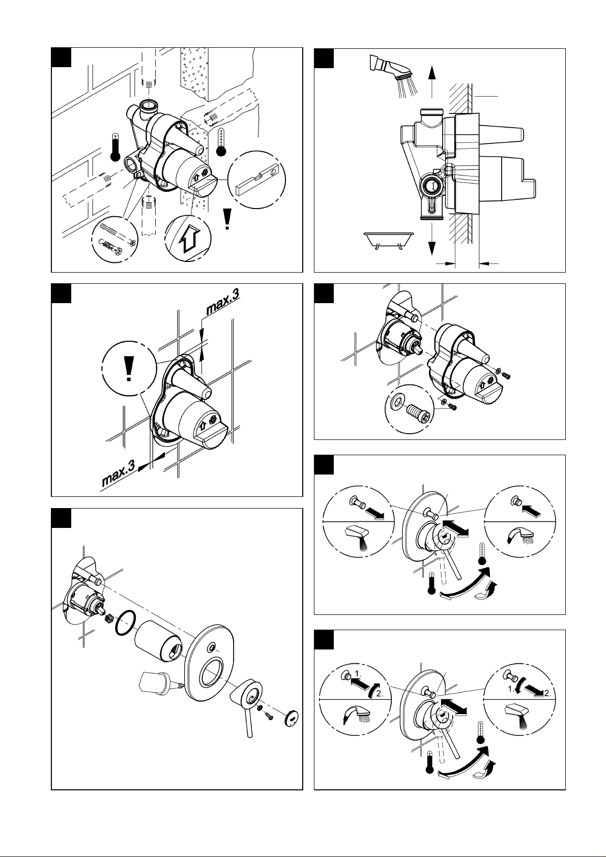
Align single lever mixer using fitting template and fit,
see fold-out page I, Figs. [1] and [2].
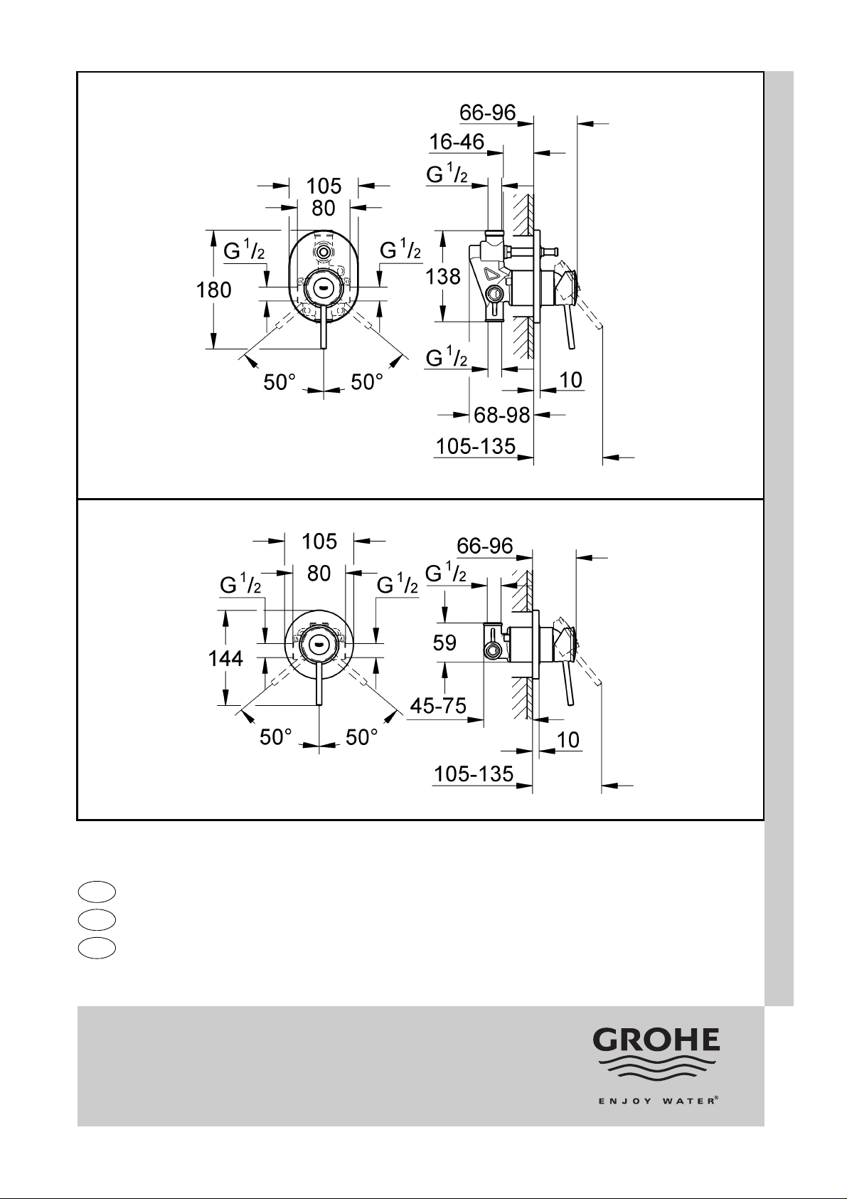
• Permissible tolerances are given on the dimensional
drawing.
• The arrow on the fitting template must point upwards.
• To align place a spirit level on the fitting template, see
Fig. [1].
• The housing is provided with pre-drilled holes (B) to facilitate
mounting the fitting to the wall.
• The finished surface of the wall (C) must lie within the
area (X) of the fitting template, see Fig. [2].
• The cold water supply must be connected on the right, hot
water supply on the left.
Connect pipes.
Open cold and hot-water supply and check connections
for water-tightness.
Flush piping system prior and after installation of fitting
thoroughly (Consider EN 806)!
Plaster and tile the wall, see Fig. [3].
Attention! You must tile directly to the fitting template!
Do not remove the fitting template before final installation.
Final installation
Remove fitting template, see Fig. [4].
Install escutcheon and lever, see Figs. [5].
Seal the escutcheon with silicone.
Check mixer for correct operation, see Fig. [6].
Function of automatic diverter (D) for 29 047, see Fig. [6].
Pulling the lever will release water delivery.
On the bath mixer, water will always emerge from the lower
outlet first (e.g. bath outlet).
Pressing diverter (D) shuts off the flow of water to the bath and
delivers water to the shower outlet.
When the mixer is closed, the diverter is released
automatically so that when the mixer is opened again, water
will always emerge from the lower outlet first (e.g. bath outlet).
Function of manual diverter (E) for 29 066, see Fig. [7].
Pulling the lever will release water delivery.
On the bath mixer, water will always emerge from the lower
outlet first (e.g. bath outlet).
Pressing diverter (E) shuts of f the flow of water to the bath and
delivers water to the shower outlet.
In addition, the diverter assembly can be secured manually
(advantageous at pressures below 0.7 bar or at low rates of
discharge). In this case, press the diverter knob of the diverter
assembly (E) and turn it clockwise.
The diverter leave in this oposition until turning anti-clockwise.
Care
Dear Customer,
We want to ensure that you get long-lasting satisfaction and
pleasure from your GROHE fitting. Therefore, please read the
following care instructions because damage to the surface and
underlying material resulting from improper treatment is not
covered by warranty.
Do not use any abrasive sponges or scouring agents for
cleaning. We also advise you not to use cleaning agents
containing solvent or acid, limescale removers, household
vinegar and cleaning agents with acetic acid in them. The y are
aggressive to the surface - and will leave your fitting dull and
scratched. As the formulations of commercially available
cleaning agents frequently change, we cannot guarantee they
will provide the gentle care our fitting deserves.
Clean the fitting with a little soap and a moist cloth only, then
simply rinse off and wipe dry. You can avoid lime spots by
drying the fitting each time it is used. If lime deposits do occur,
remove them with GrohClean, our environment-friendly
cleaning liquid. GrohClean is specially formulated to clean th e
surface of our fittings gently. GrohClean is available from your
supplier.
2
Page 5

D
Anwendungsbereich
Betrieb ist möglich mit:
• Druckspeichern
• Thermisch gesteuerten Durchlauferhitzern
• Hydraulisch gesteuerten Durchlauferhitzern
Nicht möglich ist der Betrieb mit drucklosen Speichern
(=offene Warmwasserbereiter).
Technische Daten
• Fließdruck
- min. 048 0.5 bar
- empfohlen 29 047, 29 048 1 - 5 bar
- empfohlen 29 066 1 - 5 bar
Umstellung automatisch 0,7 - 5 bar
Umstellung arretieren < 0,7 bar
• Betriebsdruck max. 10 bar
• Prüfdruck 16 bar
Zur Einhaltung der Geräuschwerte bei Ruhedrücken
über 5 bar ist ein Druckminderer einzubauen.
Höhere Druckdifferenzen zwischen Kalt- und Warmwasseranschluss sind zu vermeiden!
•Temperatur
Warmwassereingang: max. 80 °C
Zur Energieeinsparung empfohlen: 60 °C
• Wasseranschluss warm - links
kalt - rechts
Hinweis:
Durch Verwendung einer 3-Wege-Umstellung besteht die
Möglichkeit, diese Armatur mit Kopf- und Handbrausegarnitur
zu kombinieren.
Wichtig:
Bei allen Unterputzbatterien dürfen im Abgang
(Mischwasserleitung) keine Absperrventile
nachgeschaltet werden.
Installation
Einbauwand vorfertigen
• Löcher für Einhandmischer sowie Schlitze für die
Rohrleitungen erstellen.
Einhandmischer mit Einbauschablone ausrichten und
einbauen, siehe Klappseite I, Abb. [1] bis [2].
• Zulässige Toleranzen sind aus der Maßzeichnung
ersichtlich.
• Der Pfeil auf der Einbauschablone muss nach oben zeigen.
• Zum Ausrichten eine Wasserwaage auf die
Einbauschablone legen, siehe Abb. [1].
• Zur einfacheren Befestigung der Armatur an die Wand, sind
am Gehäuse Befestigungslöcher (B) vorgesehen, siehe
Abb. [1].
• Die fertige Wandoberfläche (C) muss im Bereich (X) der
Einbauschablone liegen, siehe Abb. [2].
• Der Kaltwasseranschluss muss rechts, der
Warmwasseranschluss links erfolgen.
Rohrleitungen anschließen.
Kalt- und Warmwasserzufuhr öffnen und Anschlüsse auf
Dichtheit prüfen.
Rohrleitungssystem vor und nach der Installation gründlich
spülen (DIN 1988/DIN EN 806 beachten)!
Wand fertig verputzen und verfliesen, siehe Abb. [3].
ACHTUNG! Bis direkt an die Einbauschablone verfliesen!
Einbauschablone nicht vor der Fertig installation demontieren.
Fertiginstallation
Einbauschablone entfernen, siehe Abb. [4].
Rosette und Hebel montieren, Abb. [5].
Den Rosettenbereich mit Silikon abdichten.
Funktion der Batterie prüfen, Abb. [6].
Funktion der automatischen Umstellung (D) bei 29 047,
siehe Abb. [6].
Durch Ziehen des Hebels wird die Wasserzufuhr freigegeben.
Bei der Wannenbatte rie tritt das Wasser grundsätzlich erst
zum unteren Abgang (z.B. Wannenauslauf) aus.
Durch Eindrücken der Umstellung (D) wird der
Wasserdurchlauf zur Wanne geschlossen, und das Wasser
tritt am Brausenabgang aus.
Wird die Batterie geschlossen, wird die Umstellung
automatisch herausgedrückt, so dass bei erneute m Öffnen der
Batterie das Wasser immer erst zum unteren Abgang (z.B.
Wanneneinlauf) austritt.
Funktion der manuellen Umstellung (E) bei 29 066, siehe
Abb. [7].
Durch Ziehen des Hebels wird die Wasserzufuhr freigegeben.
Bei der Wannenbatte rie tritt das Wasser grundsätzlich erst
zum unteren Abgang (z.B. Wannenauslauf) aus.
Durch Eindrücken der Umstellung (E) wird der
Wasserdurchlauf zur Wanne geschlossen, und das Wasser
tritt am Brausenabgang aus.
Zusätzlich kann die Umstellung von Hand arretiert werden.
(Vorteilhaft bei Drücken unter 0.7 bar bzw. bei geringer
Entnahmemenge). Drücken Sie dazu den Umstellknopf der
Umstellung (E) und drehen diesen mit dem Uhrzeigersinn.
Die Umstellung bleibt in dieser Position bis wieder gegen den
Uhrzeigersinn gedreht wird.
Pflege
Sehr geehrte Kundin, sehr geehrter Kunde,
Wir wollen, dass Sie lange Freude an Ihrer GROHE Armatur
haben.
Beachten Sie deshalb bitte folgende Pflegehinweise, denn
Oberflächen- und Materialschäden, die durch unsachgemäße
Behandlung entstehen, unterliegen nicht der Gewährleistung.
Verwenden Sie für die Reinigung keine kratzenden
Schwämme und Scheuermittel. Auch von lösungsmittel- oder
säurehaltigen Reinigern, Kalkentfernern, Haushaltsessig und
Reinigungsmitteln mit Essigsäure raten wir ab. Sie greifen die
Oberfläche an - Ihre Armatur wird matt und zerkratzt. Da die
Rezepturen handelsüblicher Reiniger häuf ig geändert werd en,
können wir nicht garantieren, dass sie unsere Armat ur
schonend pflegen.
Reinigen Sie die Armatur nur mit ein wenig Seife und einem
feuchten Tuch. Danach einfach abspülen und trockenreiben.
Kalkflecken können Sie vermeiden, wenn Sie die Armatur
nach jeder Benutzung abtrocknen. Sollten sich trotzdem
Kalkablagerungen bilden, beseit igen Sie diese mit
GrohClean, unserem umweltverträglichen Reinigungsmittel.
GrohClean ist mit seiner Zusammensetzung speziell auf die
schonende Pflege unserer Armaturenoberfläche abgestimmt.
GrohClean erhalten Sie bei Ihrem Installateur.
3
Page 6

D
+49 571 3989 333
✆
impressum@grohe.de
A
+43 1 68060
✆
info-at@grohe.com
AUS
Argent Sydney
+(02) 8394 5800
✆
Argent Melbourne
+(03) 9682 1231
✆
B
+32 16 230660
✆
info.be@grohe.com
BG
+359 2 9719959
✆
grohe-bulgaria@grohe.com
CAU
+99 412 497 09 74
✆
info-az@grohe.com
CDN
+1 888 6447643
✆
info@grohe.ca
CH
+41 448777300
✆
info@grohe.ch
CN
+86 21 63758878
✆
CY
+357 22 465200
✆
info@grome.com
CZ
+420 22509 1082
✆
grohe-cz@grohe.com
DK
+45 44 656800
✆
grohe@grohe.dk
E
+34 93 3368850
✆
grohe@grohe.es
EST
+372 6616354
✆
grohe@grohe.ee
F
+33 1 49972900
✆
marketing-fr@grohe.com
FIN
+358 10 8201100
✆
teknocalor@teknocalor.fi
GB
+44 871 200 3414
✆
info-uk@grohe.com
GR
+30 210 2712908
✆
nsapountzis@ath.forthnet.gr
H
+36 1 2388045
✆
info-hu@grohe.com
HK
+852 2969 7067
✆
info@grohe.hk
I
+39 2 959401
✆
info-it@grohe.com
IND
+91 124 4933000
✆
customercare.in@grohe.com
IS
+354 515 4000
✆
jonst@byko.is
J
+81 3 32989730
✆
info@grohe.co.jp
KZ
+7 727 311 07 39
✆
info-cac@grohe.com
LT
+372 6616354
✆
grohe@grohe.ee
LV
+372 6616354
✆
grohe@grohe.ee
MAL
+1 800 80 6570
✆
info-singapore@grohe.com
N
+47 22 072070
✆
grohe@grohe.no
NL
+31 79 3680133
✆
vragen-nl@grohe.com
NZ
+09/373 4324
✆
P
+351 234 529620
✆
commercial-pt@grohe.com
PL
+48 22 5432640
✆
bLXro@grohe.com.pl
RI
+62 21 2358 4751
✆
info-singapore@grohe.com
RO
+40 21 2125050
✆
info-ro@grohe.com
ROK
+82 2 559 0790
✆
info-singapore@grohe.com
RP
+63 2 8041617
✆
RUS
+7 495 9819510
✆
info@grohe.ru
S
+46 771 141314
✆
grohe@grohe.se
SGP
+65 6 7385585
✆
info-singapore@grohe.com
SK
+420 22509 1082
✆
grohe-cz@grohe.com
T
+66 2610 3685
✆
info-singapore@grohe.com
TR
+90 216 441 23 70
✆
GroheTurkey@grome.com
UA
+38 44 5375273
✆
info-ua@grohe.com
USA
+1 800 4447643
✆
us-customerservice@grohe.com
VN
+84 8 5413 6840
✆
info-singapore@grohe.com
BiHALHR KS
MK
ME
+385 1 2911470
✆
adria-hr@grohe.com
Eastern Mediterranean,
Middle East - Africa
Area Sales Office:
+357 22 465200
✆
info@grome.com
OM
IR
+971 4 3318070
✆
grohedubai@grome.com
Far East Area Sales Office:
+65 6311 3600
✆
info@grohe.com.sg
SRB
SLO
UAE YEM
www.grohe.com
2013 / 03 / 26
 Loading...