

Page 1
D
NL
PL
P
BG
CN
GB
S
UAE
TR
EST
UA
F
DK
GR
SK
LV
RUS
E
N
CZ
SLO
LT
I
FIN
H
HR
RO
29 038
DESIGN + ENGINEERING
GROHE GERMANY
99.0472.031/ÄM 238326/07.16
www.grohe.com
English .....1
Français .....1
Español .....2
.....1
.....2
.....3
.....4
.....5
.....6
.....7
.....8
.....9
...10
.....11
.....12
.....13
.....14
.....15
.....16
.....17
.....18
.....19
.....20
.....21
.....22
.....23
.....24
.....25
.....26
.....27
.....28
Page 2
Please pass these instructions on to the end user of the fitting!
S.v.p remettre cette instruction à l'utilisateur de la robinetterie!
Entregue estas instrucciones al usario final de la grifería!
I
Page 3
1
A
2,5mm
2
C
D
E
T
4
0
B
180°
Ø25/64
''
(Ø10)
180°
G
4a
15mm
4b
G
15mm
5
6
C
H
F
3a
3b
F
II
Page 4

English
Applications
Operation possible in conjunction with: Pressurized storage
heaters, thermally and hydraulically-controlled instantaneous
heaters. Operation with unpressurized stora ge heaters
(displacement water heaters) is not possible.
Built-in mixer housing / back section also suitable for:
• connection to outlet of upstream mixed water supply
Specifications
• Flow pressure
-min. 7.25 psi
- recommended 14.5 - 72.5 psi
- greater than 72.5 psi, fit pressure reducing valve
• Max. operating pressure 145 psi
• Test pressure 232 psi
• Temperature
- max. (hot water inlet) 158 °F
- Thermal disinfection possible
Installation
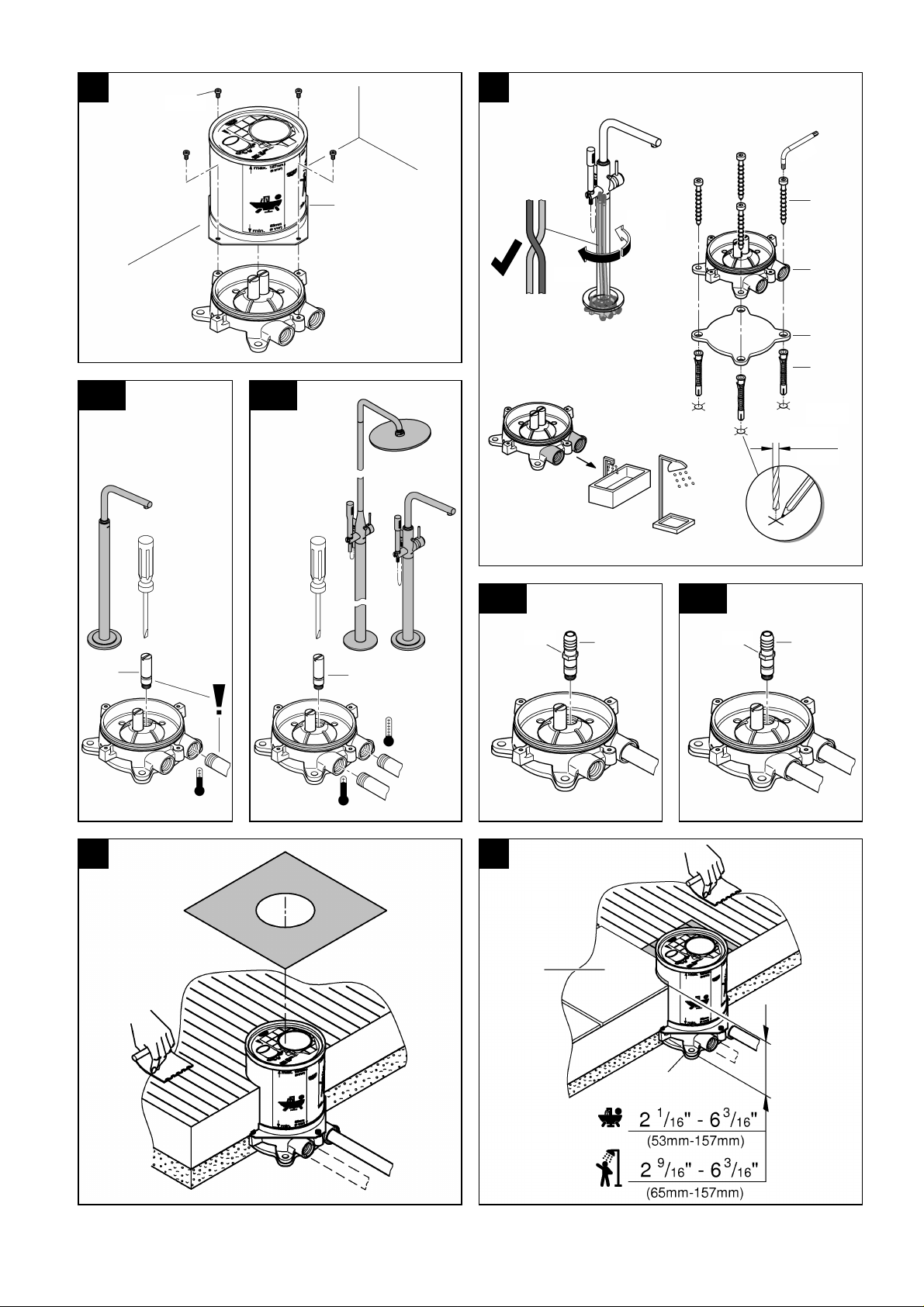
See fold-out page II, Figs. [1] to [6].
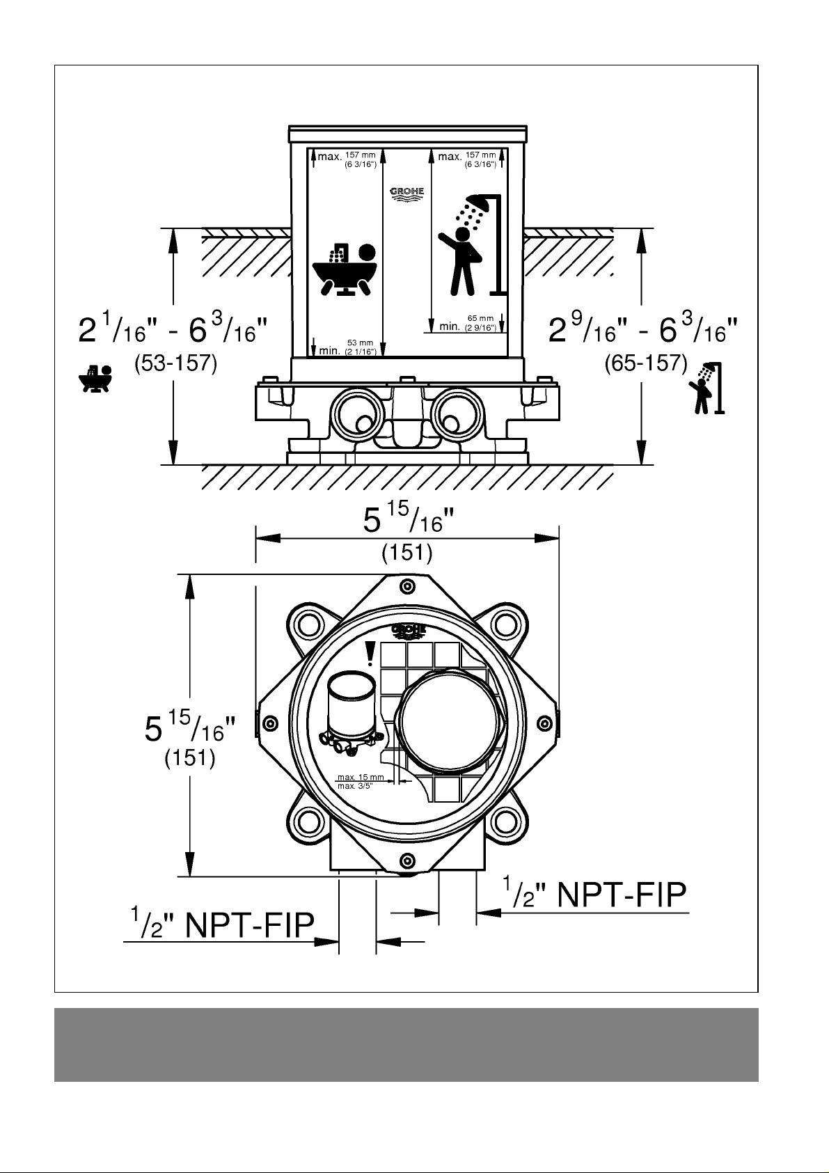
Refer to the dimensional drawing on fold-out page I.
1.Remove fitting template (A) using a 2,5mm al len wrench,
see Fig. [1].
2.Drill 25/64" holes for plugs (B), and position plate (C) and
built-in mixer housing / back section (D), see Fig. [2].
3.Insert plugs (B), tighten screws (E) using supplied wrench
and connect pipes to built-in mixer housing / back section,
see Figs. [2] and [3a] or [3b].
Important note, see Fig [3a].
The water connection can be made on the right (blue
marking on housing)or on the left (red marking on housing).
Important note, see Fig [3b].
The cold water supply must be connected on the right
(blue marking on housing) and the hot water supply on the
left (red marking on housing), as viewed from the operating
position.
Open water supply and check connections for leakage.
Flush piping system prior and after install ation of fauce t
thoroughly, see Figs. [3a] or [3b] and [4a] or [4b]!
1.Close the water supply.
2.Remove screw plug (F) on the side to which the pipe is
connected, see Fig. [3a] or [3b].
3.Screw in flushing plug (G), see Fig. [4a] or [4b].
4.Open the water supply and flush the pipes thoroughly.
5.Close the water supply and remove flushing plug (G).
6.Install screw plug (F).
7.Install fitting template (A), see Fig. [1].
The fitting depth from the lower edge of plate (C) to the
finished floor surface (H) must be between 2 1/16"
and 6 3/16" or 2 9/16" and 6 3/16", see Figs. [5] and [6].
Note: Do not cut fitting template prior to final installation.
Français
Domaine d'application
Utilisation possible avec accumulateurs sous pression,
chauffe-eau instantanés à commande thermique et
hydraulique. Un fonctionnement avec des accumu lateurs sans
pression (chauffe-eau à écoulement libre) n'est pas possible!
Corps de montage encastré également approprié pour:
• raccordement à la sortie d'une conduite d'eau mitigée en
amont
Caractéristiques techniques
• Pression dynamique
- mini. 0.5 bar
- recommandée 1 - 5 bar
- supérieure à 5 bar, mise en place d'un réducteur
de pression
• Pression de service maxi. 10 bar
• Pression d’épreuve 16 bar
• Température
- maxi. (admission d'eau chaude) 70 °C
- Désinfection thermique possible
Installation
Voir volet II, fig. [1] à [6].
Tenir compte de la cote du schéma sur le volet I.
1.Dévisser le gabarit de montage (A) avec une clé Allen
de 2,5mm, voir volet [1].
2.Percer des trous pour les chevilles (B) de 10mm, insérer la
plaque (C) et le corps encastré (D), voir fig. [2].
3.Insérer les chevilles (B), serrer les vis (E) avec la clé fournie
et brancher les canalisations au corps encastré, voir fig. [2]
et [3a] ou [3b].
Important, voir fig. [3a]!
Le raccordement d'eau est possible à droite (repère bleu
sur le boîtier) ou à gauche (repère rouge sur le boîtier).
Important, voir fig. [3b]!
Brancher l'eau froide à droite (repère bleu sur le boîtier)
et l'eau chaude à gauche (repère rouge sur le boîtier).
Ouvrir l'arrivée d'eau froide et d'eau chaude et vérifier
l'étanchéité des raccordements.
Bien rincer les canalisations avant et après l’installation,
voir fig. [3a] ou [3b] et [4a] ou [4b]!
1.Fermer l'arrivée d'eau.
2.Dévisser la vis de fermeture (F) du côté de la canalisation
raccordée, voir fig. [3a] ou [3b].
3.Visser le bouchon de rinçage (G), voir fig. [4a] ou [4b].
4.Ouvrir l'alimentation en eau et bien purger les tuyauteries.
5.Fermer l’alimentation en eau et enlever les bouchons (G).
6.Visser le bouchon fileté (F).
7.Installer le gabarit de montage (A), voir la fig. [1].
La profondeur de montage du bord inférieur de la plaque (C)
jusqu'à la surface du sol préparé (H) doit se situer entre 53mm
et 157mm ou 65mm et 157mm, voir fig. [5] et [6].
Remarque: Ne pas raccourcir le gabarit de montage avant
l'installation finale.
1
Page 5

Español
Campo de aplicación
Es posible el funcionamiento con: acumulado r es de presión,
calentadores instantáneos con control térmico e hidráulico.
No es posible el funcionamiento con acumuladores sin presión
(calentadores de agua sin presión).
Cuerpo de montaje empotrable adecuado adicionalmente
para:
• Conexión a la salida de un abastecimiento an tepuesto de
agua mezclada
Datos técnicos
•Presión
- mín. 7.25 psi
- recomendada 14.5 - 72.5 psi
- si la presión es superior a 72.5 psi, se debe rá
instalar una válvula reductora de presión
• Presión de utilización máx. 145 psi
• Presión de verificación 232 psi
• Temperatura
- máx. (entrada del agua caliente) 158 °F
- Desinfección térmica posible
Instalación
Véase la página desplegable II, figs. [1] a [6].
Respetar el croquis de la página desplegable I.
1.Desatornillar la plantilla de montaje (A) con una llave de
macho hexagonal de 2,5mm, véase la fig. [1].
2.Realizar los taladros para los tacos (B) de 25/64" y colocar
la placa (C) y el cuerpo de montaje empotrable (D), véase la
fig. [2].
3.Colocar los tacos (B), apretar los tornillos (E) con la llave
adjunta y conectar las tuberías al cuerpo de montaje
empotrable, véanse las figs. [2] y [3a] o [3b].
¡Importante, véase la fig. [3a]!
La acometida del agua puede conectarse a la derecha
(marca azul en la carcasa) o a la izquierda (marca roja en la
carcasa).
¡Importante, véase la fig. [3b]!
La acometida del agua fría debe conectarse a la derecha
(marca azul en la carcasa) y la del agua caliente debe
conectarse a la izquierda (marca roja en la carcasa).
Abrir las llaves de paso del agua fría y del agua caliente y
comprobar la estanqueidad de las conexiones.
¡Purgar a fondo el sistema de tuberías antes y después
de la instalación, véanse las figs. [3a] o [3b] y [4a] o [4b]!
1.Cerrar la alimentación de agua.
2.Sacar desatornillando el tapón roscado (F) del lado de la
tubería conectada, véase la fig. [3a] o [3b].
3.Enroscar el tapón de purga (G), véase la fig. [4a] o [4b].
4.Abrir la alimentación de agua y purgar a fondo las tuberías.
5.Cerrar la alimentación de agua y quitar el tapón de
purga (G).
6.Enroscar el tapón roscado (F).
7.Instalar la plantilla de montaje (A), véase la fig. [1].
La profundidad de montaje desde el borde inferior de la
placa (C) hasta la superficie acabada del suelo (H) debe estar
entre 2 1/16" y 6 3/16" o 2 9/16" y 6 3/16", véanse las figs. [5]
y[6].
Nota: No acortar la plantilla de mont aje antes de proceder a la
instalación de acabado.
2
Page 6
2014/03/21
www.grohe.com
D
A
AUS
Argent Sydney
&
+(02) 8394 5800
Argent Melbourne
&
+(03) 9682 1231
B
BG
CAU
CDN
CH
CN
&
+86 21 63758878
CY
CZ
DK
E
EST
F
FIN
GB
GR
H
HK
I
IND
IS
J
KZ
LT
LV
MAL
N
NL
NZ
&
+09/373 4324
P
PL
RI
RO
ROK
RP
&
+63 2 8041617
RUS
S
SGP
SK
T
TR
UA
USA
VN
BiH
AL
HR
KS
ME
MK
SLO
SRB
&
+385 1 2911470
Eastern Mediterranean,
Middle East - Africa
Area Sales Office:
&
+357 22 465200
IR
OM
UAE YEM
 Loading...