

Page 1
D
.....1
NL
.....6
PL
.....11
P
.....16
BG
.....21
CN
.....26
GB
.....2
S
.....7
UAE
.....12
TR
.....17
EST
.....22
UA
.....27
F
.....3
DK
.....8
GR
.....13
SK
.....18
LV
.....23
RUS
.....28
E
.....4
N
.....9
CZ
.....14
SLO
.....19
LT
.....24
I
.....5
FIN
...10
H
.....15
HR
.....20
RO
.....25
DESIGN + ENGINEERING
GROHE GERMANY
www.grohe.com
19 843
19 844
99.791.031/ÄM 219326/10. 11
English .....1
Français .....6
Español ....11
Page 2
I
S.v.p remettre cette instruction à l'utilisateur de la robinetterie!
Entregue estas instrucciones al usario final de la grifería!
Please pass these instructions on to the end user of the fitting!
I
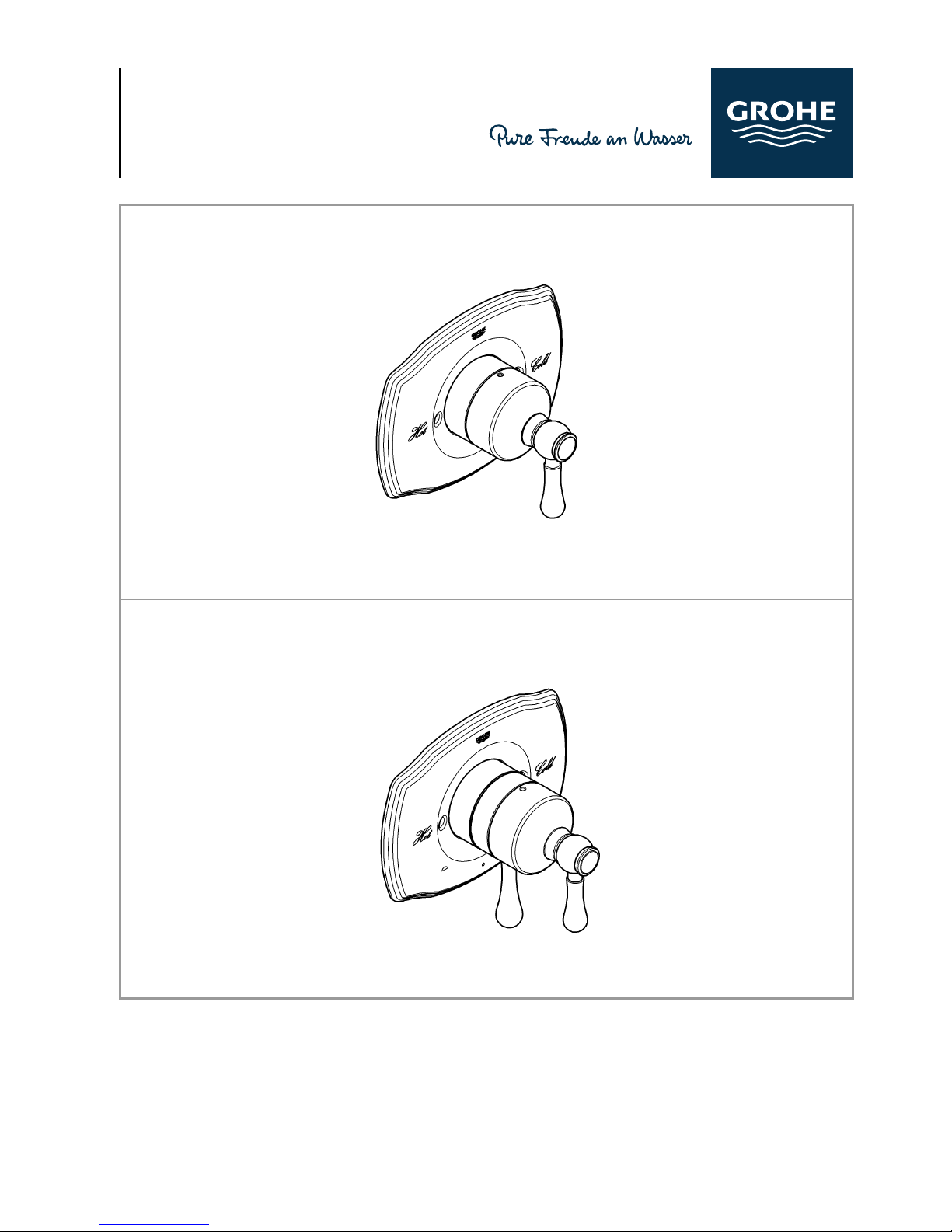
Type #1
19 843
Type #2
19 844
Page 3
II II
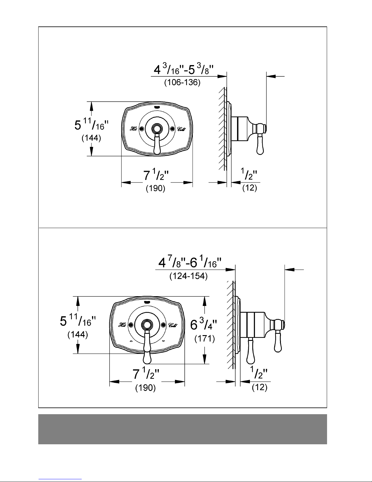
Type #1
19 843
Type #2
19 844
Page 4
Please pass these instructions on to the end user of the faucet!
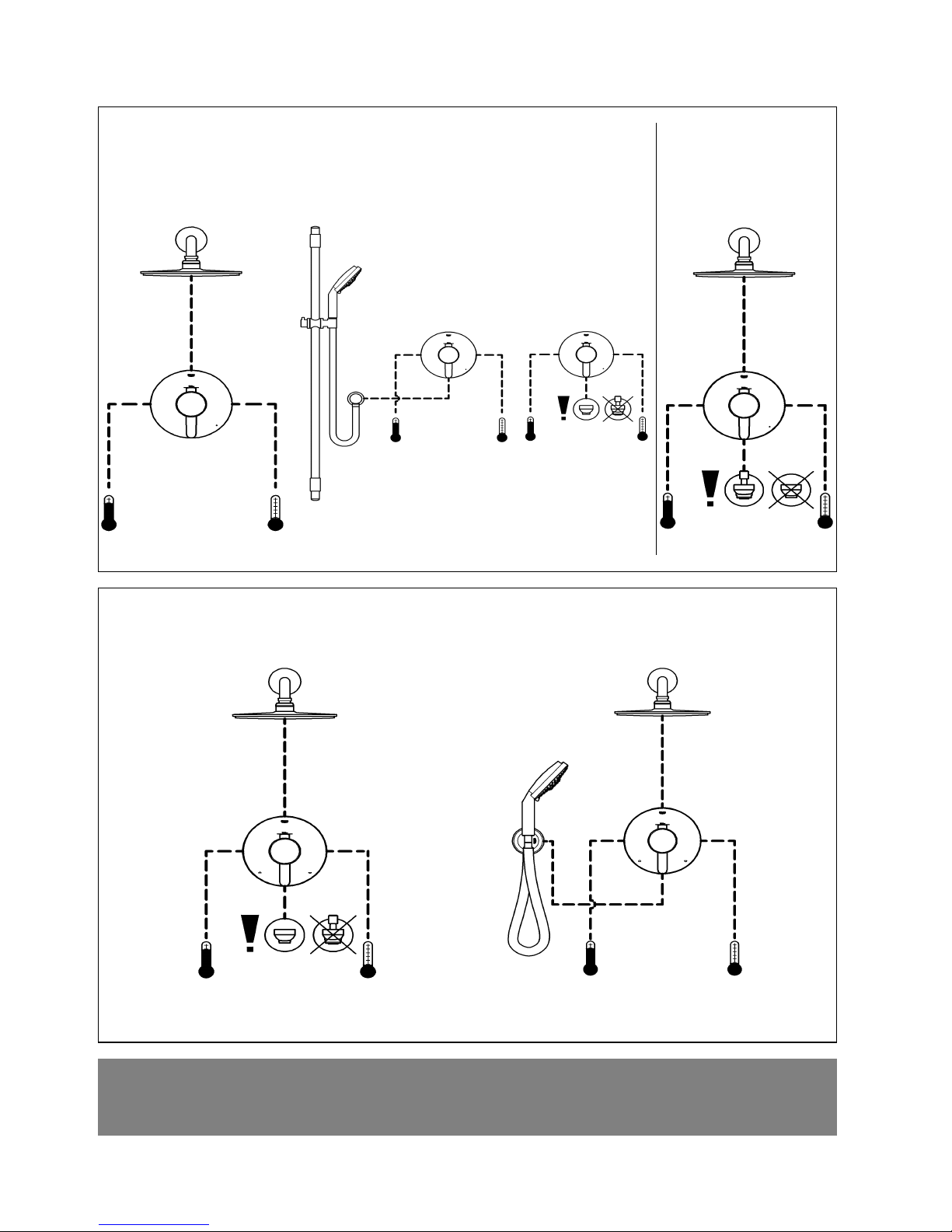
without bypass use with use of integrated
PBV trim type #1 (single use)
bypass
PBV trim type #2 (integrated two way diverter)
Installation options with different types of trims
1
Page 5
2
English
General Application
These Pressure Balance Valves are for use with GrohFlexTM
universal rough-in valve.
Planing of piping is done at the time of the rough installation.
2 different types of PBVs are possible.
Observe the possible combinations, see Page 1.
Specification
• Concealed single handle pressure balancing valve for tub
and shower
• Integral service stops
• Integral check valves prevent cross flow
• Pressure balanced diaphragm cartridge automatically
adjusts to inlet pressure fluctuations
• Cartridge restricts hot water supply if the cold pressure fails,
to prevent scalding
• Flow pressure:
- min 1 bar or 14.5 psi
- recommended 1-5 bar or 14.5 – 72.5 psi
If greater than 5 bar or 72.5 psi, fit pressure reducing valve
• Max. operating pressure 8.5 bar or 125 psi
• Max. test pressure 34.5 bar or 500 psi
• Flow rates at 3 bar or 45 psi
- Type #1 19 843 23 l/min or 6,1 gpm
- Type #2 19 844
bottom outlet 20 l/min or 5,3 gpm
top outlet 11 l/min or 2,9 gpm
• Temperature
- max. (hot water inlet) 80 °C or 180 °F
- The handle rotation stop may be used to limit the maximum
temperature. The maximum temperature will be reached
when the handle is turned in a counter-clockwise direction.
• Back-to-back installation is possible by reversing the
pressure balancing cartridge.
• Water connection: cold - RH
hot - LH
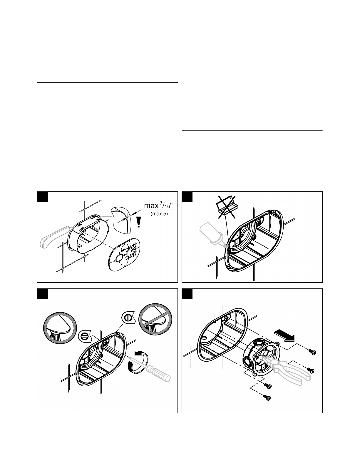
General preparation
1.Cut of the excess blue box material, see fig. [1].
2.Seal the rough-in valve, see fig. [2].
3.Close the integrated service stops, see fig. [3].
4.Remove flush cap, see fig. [4].
1
2
3
4
Page 6
3
English
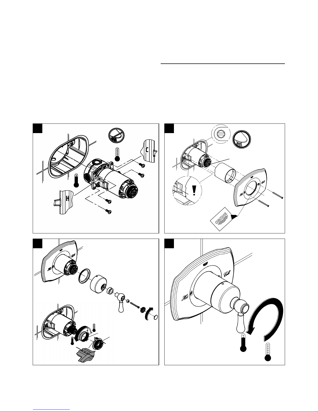
Installation Type #1 19 843
If both rough-in outlets are used, you have to install a spout
with diverter. If only the lower rough-in outlet is used, you
have to install a spout without diverter.
1.Install control unit and secure with screws, see Fig. [5].
2.Close valve by turning the adaper (A) clockwise until it
stops, see Fig. [6].
3.Open the hot and cold integrated service stops.
4.For installation of handle parts, see Fig. [7].
5.While installation observe the right mounting position.
If the pressure balancing valve is installed too deep, the
fitting depth can be increased by 25mm or 1" with an extension
set, Part No. 47 823, see page II.
Note:
The preset maximum temperature will change if the inlet
temperatures change or the setting of the water heater
thermostat is altered or if the water inlet temperature is
fluctuating.
Operation
Turn lever anti-clockwise:
- Open from cold to hot water flow, see Fig. [8].
The adjustable hot water limit stop (B) is factory set at a
position to limit maximum outlet temperature to below the hot
water supply temperature, see Fig. [7]. For installations where
there is need to modify the limit temperature, remove the limit
stop (B) and replace in a more clockwise position for colder
water, or more counter-clockwise position for hotter water.
Observe the mounting position of stop (C).
6
A
8
5
7
B
C
Page 7

4
English
4
Installation Type #1 19 843
If both rough-in outlets are used, you have to install a spout
with diverter. If only the lower rough-in outlet is used, you
have to install a spout without diverter.
1.Install control unit and secure with screws, see Fig. [5].
2.Close valve by turning the adaper (A) clockwise until it
stops, see Fig. [6].
3.Open the hot and cold integrated service stops.
4.For installation of handle parts, see Fig. [7].
5.While installation observe the right mounting position.
If the pressure balancing valve is installed too deep, the
fitting depth can be increased by 25mm or 1" with an extension
set, Part No. 47 823, see page II.
Note:
The preset maximum temperature will change if the inlet
temperatures change or the setting of the water heater
thermostat is altered or if the water inlet temperature is
fluctuating.
Operation
Turn lever anti-clockwise:
- Open from cold to hot water flow, see Fig. [8].
The adjustable hot water limit stop (B) is factory set at a
position to limit maximum outlet temperature to below the hot
water supply temperature, see Fig. [7]. For installations where
there is need to modify the limit temperature, remove the limit
stop (B) and replace in a more clockwise position for colder
water, or more counter-clockwise position for hotter water.
Observe the mounting position of stop (C).
5
6
A
7
B
E
C
8
9
D
E
D
E
Page 8

5
English
Winterizing the system
It is recommended that the "pressure balancing cartridge"
be removed from the valve body if the system is to be shut off
during the winter.
Maintenance
Important note: If the control unit is to be removed from
the rough-in for servicing, first close the inlet stops then
open the flow control to allow any internal pressure to be
released from within the unit.
Inspect and clean all parts, replace if necessary and grease
with special valve grease.
Close the integrated service stops!
I. Non return valves, see Fig. [10a] or [10b] and [11].
Install in reverse order.
Open the integrated service stops!
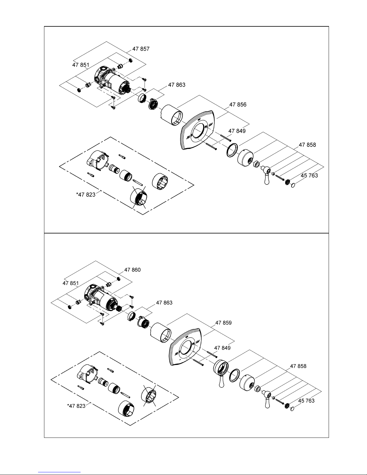
Replacement parts, see page II (* = special accessories).
Care
Instructions for care of this faucet will be found in the Limited
Warranty supplement.
Type #1
19 843
10a
10b
Type #2
19 844
11
Page 9

S.V.P. remettre ces instructions à l’utilisateur final de la robinetterie!
utilisation sans dérivation avec utilisation d’une
Équilibreur depression de type #1 (usage unique)
dérivation intégrée
Équilibreur depression de type #2 (inverseur à deux voies)
Options d’installation avec divers types d’organes
6
Page 10

7
Français
Application générale
Ces équilibreurs depression sont conçus pour une utilisation
avec la robinetterie brute universelle GrohFlex
TM
.
La planification de la tuyauterie est réalisée au moment
l’installation provisoire.
2 types d’EDP sont possibles.
Respecter les combinaisons possible, voir page 1.
Caractéristiques techniques
• Robinet encastré de régulation de pression de baignoire et
douche à poignée unique.
• Robinet d’arrêt intégral
• Les robinets de contrôle intégraux empêchent les
écoulements parasites
• La cartouche à membrane de régulation de pression
s’adapte automatiquement aux variations de pression
d’entrée
• La cartouche limite la quantité d’eau chaude si la pression
d’eau froide est insuffisante, afin d’éviter tout risque de
brûlure
• Pression dynamique:
- min 1 bar ou 14,5 psi
- recommandée 1-5 bar ou 14,5 – 72.5 psi
Installer un réducteur de pression lorsque la pression est
supérieure à 5 bar ou 72.5 psi
• Pression de service maxi 8,5 bar ou 125 psi
• Pression d’épreuve maxi 34,5 bar ou 500 psi
• Débits à une pression de 3 bars ou 45 psi
- Type #1 19 843 23 l/min ou 6,1 gpm
- Type #2 19 844
sortie du bas 20 l/min ou 5,3 gpm
sortie du haut 11 l/min ou 2,9 gpm
• Température
- maxi. (entrée d’eau chaude) 80 °C ou 180 °F
- Il est possible de tourner la poignée pour limiter la
température maximale. La température maximale est
atteinte lorsque la poignée est tournée dans le sens inverse
des aiguilles d’une montre.
• L’inst allation inversée est possible en inve rsant la cartouche
de régulation de pression.
• Raccord d’eau: froide - à droite
chaude - à gauche
Préparation générale
1.Couper l'excédent du matériel boîte bleue, voir fig. [1].
2.Installer le joint sur la robinetterie brute, voir fig. [2].
3.Fermer les robinets d’arrêt intégrés, voir fig. [3].
4.Enlever le capuchon ras, voir fig. [4].
1
2
3
4
Page 11

8
Français
Installation type #1 19 843
Si les deux sorties provisoires sont utilisées, vous devez
installer un bec à inversion.
Si seule la partie inférieure rugueuse en sortie est utilisé, vous
devez installer un bec sans inverseur.
1.Installer l‘unité contrôle et fixer avec des vis, voir fig. [5].
2.Fermer le robinet en tournant l’adaptateur (A) à fond dans le
sens des aiguilles d’une montre, voir fig. [6].
3.Ouvrir le s r obinets d’arrêt chaud et froid intégré.
4.Installation des pièces de la poignée, voir fig. [7].
5.Pend ant l’installation, respecter la bonne position de
montage.
Si l’équilibreur de pression est installé trop profondément,
la profondeur de montage peut être accrue de 25mm ou or 1"
avec un kit de prolongation, réf. 47 823, voir page II.
Remarque:
La température maximale préréglée change si les t empératures
d’entrée changent, si le réglage du thermostat du chauffe-eau
est modifié ou si la température d’entrée d’eau fluctue.
Fonctionnement
T ourner le levier dans le sens inverse des aiguilles d’une montre:
- Ouvrir de l’écoulement d’eau froide vers le chaud,voir fig.[8].
La butée réglable d’eau chaude (B) est réglée en usine sur
une position permettant de limiter la température maximale de
sortie à une valeur inférieure à celle de la température
d’alimentation en eau chaude, voir fig. [7]. Pour les
installations où il est nécessaire de modifier la limite de
température, dévisser la butée (B) et la remettre en place en la
tournant un peu plus dans le sens des aiguilles d’une montre
pour une température plus froide, ou plus dans le sens inverse
des aiguilles d’une montre pour une eau plus chaude.
Respecter la position de montage de la butée (C).
8
5
6
A
7
B
C
Page 12

9
Français
Installation type #2 19 844
1.Installer l‘ unité contrôle et fixer avec des vis, voir fig. [5].
2.Fermer l’écoulement d’eau en tournant l’arcade. Le
repère (A) doit se trouver en haut, un clic est perceptible/
audible dans l’arcade, voir fig. [6].
3.Ouvrir les robinets d’arrêt chaud et froid intégrés, voir fig. [7].
4.Pend ant l’installation, respecter la bonne position de
montage.
5.Installation des pièces de la poignée, voir fig. [7] et [8].
Si l’équilibreur de pression est installé trop profondément,
la profondeur de montage peut être accrue de 25mm ou 1”
avec un kit de prolongation, réf. 47 823, voir page II.
Remarque : La température maximale préréglée change si les
températures d’entrée changent, si le réglage du thermostat du
chauffe-eau est modifié ou si la température d’entrée d’eau
fluctue.
Fonctionnement, voir fig. [9].
Tourner le levier (D) dans le sens inverse des aiguilles d’une
montre:
- Sélect de l’écoulement d’eau froide vers le chaud.
Tourner le levier (E) vers la gauche ou la droite:
Ouvrir la sortie d’eau lors de la préparation de l’installation
de la tuyauterie.
- ouvrir vers la gauche pour la sortie haute
- ouvrir vers la droite pour la sortie basse
La butée réglable d’eau chaude (B) est réglée en usine sur
une position permettant de limiter la température maximale de
sortie à une valeur inférieure à celle de la température
d’alimentation en eau chaude, voir fig. [7]. Pour les
installations où il est nécessaire de modifier la limite de
température, dévisser la butée (B) et la remettre en place en la
tournant un peu plus dans le sens des aiguilles d’une montre
pour une température plus froide, ou plus dans le sens inverse
des aiguilles d’une montre pour une eau plus chaude.
Respecter la position de montage de la butée (C).
5
6
A
7
B
E
C
8
9
D
E
D
E
Page 13

10
Français
Préparation de l’installation pour l’hivernage
Il est conseillé de déposer la « cartouche de réduction de
pression » du moulage du robinet si l’installation doit être
fermée pendant l’hiver.
Maintenance
Remarque importante: Si l'unité de commande doit être
déposée de l'installation provisoire pour maintenance,
fermer d'abord les butées d'entrée, puis ouvrir le
régulateur de débit pour permettre l'évacuation de la
pression interne de l'intérieur de l'unité.
Inspecter et nettoyer toutes les pièces, les remplacer si
nécessaire et les graisser avec une graisse pour robinetterie.
Fermer les robinets d’arrêt intégrés!
I. Clapets anti-retour, voir fig. [10a] ou [10b] et [11].
L’installation s’effectue dans l’ordre inverse.
Ouvrir les robinets d’arrêt intégrés!
Pièces de rechange, voir page II (* = accessoires spéciaux).
Entretien
Les instructions d’entretien de ce robinet sont indiquées dans
le supplément de garantie limitée.
Type #1
19 843
10a
10b
Type #2
19 844
11
Page 14

Proporcione estas instrucciones al usuario final del montaje.
sin derivación con derivación
Tipo mandos de compensación de presión n.º1 (uso único)
integrada
Tipo mandos de compensación de presión n.º 2 (inversor de dos vías integrado)
Opciones de instalación con distintos tipos de montajes
11
Page 15

12
Español
Campo de aplicación general
Estos mandos de compensación de presión deben utilizarse
con la válvula oculta GrohFlex
TM
universal.
La planificación de las tuberías se efectúa con la instalación
inicial.
Se admiten 2 tipos distintos de mandos de compensación de
presión.
Observe las posibles combinaciones en la página 1.
Especificaciones
• Válvula de compensación de presión monomando oculta
para bañera y ducha
• Topes de paso integrados
• Válvulas de cierre integradas para prevenir el caudal
transversal
• El cartucho de membrana regulado por presión se ajusta
automáticamente a las fluctuaciones de presión de entrada
• El cartucho restringe el suministro de agua caliente si cae la
presión del agua fría para evitar escaldaduras
• Presión de trabajo:
- mín. 1 bar o 14,5 psi
- recomendado 1-5 bares o 14,5 – 72,5 psi
superior a 5 bar ou 72,5 psi, instalar una válvula reductora de
presión
• Presión de utilización máx. 8,5 bares o 125 psi
• Presión de verificación máx. 34,5 bares o 500 psi
• Caudal a 3 bares o 45 psi
- Tipo n.º 1 19 843 23 l/min o 6,1 gpm
- Tipo n.º 2 19 844
salida inferior 20 l/min o 5,3 gpm
salida superior 11 l/min o 2,9 gpm
• Temperatura
- máx. (entrada de agua caliente) 80 °C o 180 °F
- Para limitar la temperatura máxima, se puede girar el mando.
La temperatura máxima se alcanza cuando el mando se
gira en sentido contrario a las agujas del reloj.
• Es posible la instalación adosada invirtiendo el cartucho de
regulación de presión.
• Acometida del agua: fría - derecha
caliente - izquierda
Preparación general
1.Corte del material de exceso de caja azul; véase la fig. [1].
2.Selle la válvula oculta; véase la fig. [2].
3.Cierre los topes de paso integrados; véase la fig. [3].
4.Quite la tapa al ras; véase la fig. [4].
1
2
3
4
Page 16

13
Español
Instalación tipo n.º 1 19 843
Si se utilizan ambas salidas ocultas, se deberá instalar un
caño de inversión. Si sólo la parte inferior rugosa en la salida
se utiliza, tiene que instalar un caño sin inversor.
1. Inst ale unidad de control y fíjela con tornillos; véase la fig. [5].
2.Cierre la válvula girando el adaptador (A) en el sentido de
las agujas del reloj hasta que se detenga; véase la fig. [6].
3.Abra los topes de paso integrados para agua caliente y fría.
4.Instale las piezas independientes de la empuñadura; véase
la fig. [7].
5.Durante la instalación, observe la posición de montaje
correcta.
Si el mando de compensación de presión se instala a
demasiada profundidad, la profundidad de montaje puede
aumentarse en 25mm o 1" con un juego de prolongación (n.º
de producto 47 823); véase la página II.
Nota:
La temperatura máxima preconfigurada cambiará si las
temperaturas de entrada varían, si la configuración del
termostato del calentador de agua se modifica o si la
temperatura de entrada de agua fluctúa.
Funcionamiento
Gire la palanca en el sentido contrario de las agujas del reloj:
- Abra la salida de agua de fría a caliente; véase la fig. [8].
El limitador ajustable de tope de agua caliente (B) está
configurado de fábrica en una posición a fin de limitar la
máxima temperatura de salida por debajo de la temperatura
de la alimentación de agua caliente; véase la fig. [7]. En
aquellas instalaciones en las que sea necesario modificar la
temperatura límite, retire el limitador de tope (B) y vuelva a
colocarlo en una posición desplazada en el sentido de las
agujas del reloj para el agua fría, o en el sentido contrario al
de las agujas del reloj para el agua caliente.
Observe la posición de montaje del tope (C).
6
A
8
7
B
C
5
Page 17

14
Español
Instalación tipo n.º 2 19 844
1.Instale unidad de control y fíjela con tornillos; véase la
fig. [5].
2.Gire la horquilla para cerrar el flujo de agua. La marca (A)
debe estar en la parte superior. Escuchará/notará un “clic”
en la horquilla; véase la fig. [6].
3.Abra los topes de paso integrados para agua caliente y fría;
véase la fig. [7].
4.Durante la instalación, observe la posición de montaje
correcta.
5.Tras el ajuste, instale las piezas indepe ndientes de la
empuñadura; véanse las figs. [7] y [8].
Si el mando de compensación de presión se instala a
demasiada profundidad, la profundidad de montaje puede
aumentarse en 25mm ou 1" con un juego de prolongación
(n.º de producto 47 823); véase la página II.
Nota: La temperatura máxima preconfigurada cambiará si las
temperaturas de entrada varían, si la configur ación del
termostato del calentador de agua se modifica o si la
temperatura de entrada de agua fluctúa.
Funcionamiento; véase la fig. [9].
Gire la palanca (D) en el sentido contrario de las agujas del
reloj:
- Selecto la salida de agua de fría a caliente.
Gire la palanca (E) a la izquierda o a la derecha:
Abra la salida de agua cuando la instalación de la tubería
esté lista.
- apertura izquierda a salida superior
- apertura derecha a salida inferior
El limitador ajustable de tope de agua caliente (B) está
configurado de fábrica en una posición a fin de limitar la
máxima temperatura de salida por debajo de la temperatura
de la alimentación de agua caliente; véase la fig. [7]. En
aquellas instalaciones en las que sea necesario modificar la
temperatura límite, retire el limitador de tope (B) y vuelva a
colocarlo en una posición desplazada en el sentido de las
agujas del reloj para el agua fría, o en el sentido contrario al
de las agujas del reloj para el agua caliente.
Observe la posición de montaje del tope (C).
14
7
B
E
C
5
6
A
9
D
E
D
E
8
Page 18

15
Español
Protección del sistema frente al invierno
Se recomienda extraer el "cartucho de regulación de
presión" de la válvula de fundición si el sistema debe
apagarse durante el invierno.
Mantenimiento
Importante: Si la unidad de control ha de retirarse de la
instalación inicial para el mantenimiento, cierre primero
los topes de admisión y abra seguidamente el regulador
de caudal para permitir que se alivie cualquier presión
interna desde el interior de la unidad.
Inspeccione y limpie todos los componentes, sustituya los que
sean necesarios y lubrique con grasa especial para grifería.
Cierre los topes de paso integrados.
I. Válvulas antirretorno; véanse las figs. [10a] o [10b] y [11].
Instale en el orden inverso.
Abra los topes de paso integrados.
Piezas de recambio; véase la página II (* = accesorios
especiales).
Cuidados
Las instrucciones de conservación de esta grifería se
encuentran en el anexo de la garantía.
Tipo n.º 1
19 843
10a
10b
Tipo n.º 2
19 844
11
Page 19

Page 20

2014/03/21
www.grohe.com
D
&
+49 571 3989 333
impressum@grohe.de
A
&
+43 1 68060
info-at@grohe.com
AUS
Argent Sydney
&
+(02) 8394 5800
Argent Melbourne
&
+(03) 9682 1231
B
&
+32 16 230660
info.be@grohe.com
BG
&
+359 2 9719959
grohe-bulgaria@grohe.com
CAU
&
+99 412 497 09 74
info-az@grohe.com
CDN
&
+1 888 6447643
info@grohe.ca
CH
&
+41 448777300
info@grohe.ch
CN
&
+86 21 63758878
CY
&
+357 22 465200
info@grome.com
CZ
&
+420 277 004 190
grohe-cz@grohe.com
DK
&
+45 44 656800
grohe@grohe.dk
E
&
+34 93 3368850
grohe@grohe.es
EST
&
+372 6616354
grohe@grohe.ee
F
&
+33 1 49972900
marketing-fr@grohe.com
FIN
&
+358 10 8201100
teknocalor@teknocalor.fi
GB
&
+44 871 200 3414
info-uk@grohe.com
GR
&
+30 210 2712908
nsapountzis@ath.forthnet.gr
H
&
+36 1 2388045
info-hu@grohe.com
HK
&
+852 2969 7067
info@grohe.hk
I
&
+39 2 959401
info-it@grohe.com
IND
&
+91 124 4933000
customercare.in@grohe.com
IS
&
+354 515 4000
jonst@byko.is
J
&
+81 3 32989730
info@grohe.co.jp
KZ
&
+7 727 311 07 39
info-cac@grohe.com
LT
&
+372 6616354
grohe@grohe.ee
LV
&
+372 6616354
grohe@grohe.ee
MAL
&
+1 800 80 6570
info-singapore@grohe.com
N
&
+47 22 072070
grohe@grohe.no
NL
&
+31 79 3680133
vragen-nl@grohe.com
NZ
&
+09/373 4324
P
&
+351 234 529620
commercial-pt@grohe.com
PL
&
+48 22 5432640
biuro@grohe.com.pl
RI
&
+62 21 2358 4751
info-singapore@grohe.com
RO
&
+40 21 2125050
info-ro@grohe.com
ROK
&
+82 2 559 0790
info-singapore@grohe.com
RP
&
+63 2 8041617
RUS
&
+7 495 9819510
info@grohe.ru
S
&
+46 771 141314
grohe@grohe.se
SGP
&
+65 6 7385585
info-singapore@grohe.com
SK
&
+420 277 004 190
grohe-cz@grohe.com
T
&
+66 2610 3685
info-singapore@grohe.com
TR
&
+90 216 441 23 70
GroheTurkey@grome.com
UA
&
+38 44 5375273
info-ua@grohe.com
USA
&
+1 800 4447643
us-customerservice@grohe.com
VN
&
+84 8 5413 6840
info-singapore@grohe.com
BiH
AL
HR
KS
ME
MK
SLO
SRB
&
+385 1 2911470
adria-hr@grohe.com
Eastern Mediterranean,
Middle East - Africa
Area Sales Office:
&
+357 22 465200
info@grome.com
IR
OM
UAE YEM
&
+971 4 3318070
grohedubai@grome.com
Far East Area Sales Office:
&
+65 6311 3600
info@grohe.com.sg
 Loading...