

Page 1
1.Twin-3
Your efficiency is our Challenge!
F210613 rev.00
NL Gebruiksaanwijzing electrische vatpomp
UK User’s Instruction electrical drum pump
Page 2

2
1.
Nederlands . . . . . . . . . . . . . . . . . . . . . . . . . . . . . . . . . . . . . . . . . . . . . 6
English. . . . . . . . . . . . . . . . . . . . . . . . . . . . . . . . . . . . . . . . . . . . . . . . 14
F210613 rev.00
Page 3
3
1.
7
6
5
4
8
9
10
2
3
1
A
F210613 rev.00
Page 4
4
1.
18
19
17
20
16
21
22
23
24
25
26
15
14
13
12
11
27
B
F210613 rev.00
Page 5
5
abcd ef ghi
1.
PUMP
L
T
POWER
PUMP
VAL1
VAL2
LOW
TEST
J5
2 GND
1 +15
3
7PS
PS
8
6 K
5
4 +SL
+-
I
I
BK
RD
TWIN
Automatic
Greasing
System
SWITCH
P
GN
BU
GY
PU
+
/
-
jk lmn
F210613 rev.00
34
J8
WH
YE
o
C
Page 6

6
1. GEBRUIKSAANWIJZING
Voorwoord
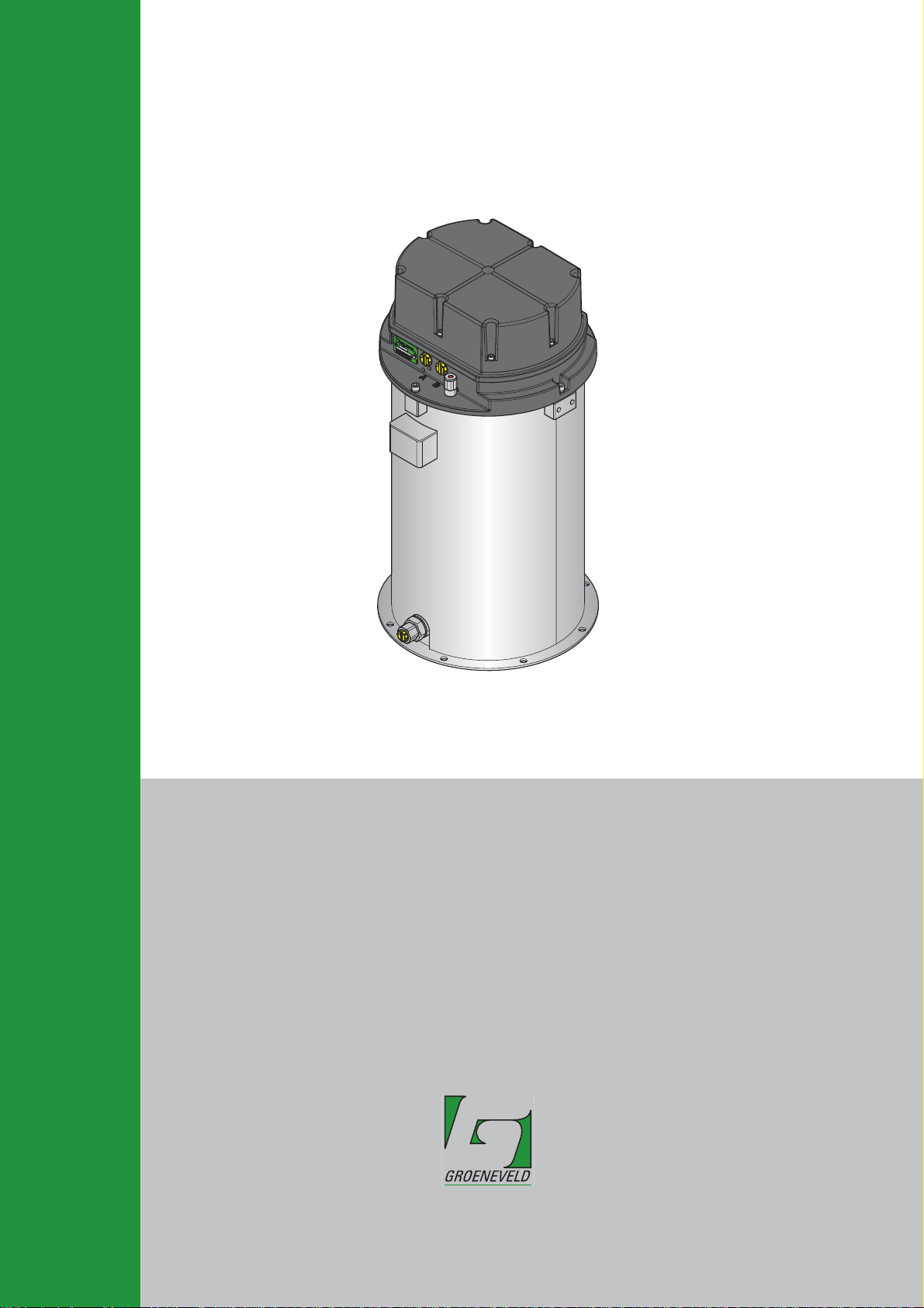
Deze gebruikersaanwijzing geeft een omschrijving van de Twin-3 elektrische
vatpomp. De bedoeling is de gebruiker inzicht te geven in de werking en
onderhoudsaspecten van de Twin-3 elektrische vatpomp.
Daarnaast vindt u in deze gebruikersaanwijzing de technische gegevens van de
Twin-3 elektrische vatpomp.
In deze gebruikersaanwijzing zijn de volgende pictogrammen gebruikt om de
gebruiker te attenderen of te waarschuwen:
LET OP
Attendeert de gebruiker op belangrijke aanvullende informatie met
als doel problemen te voorkomen.
WAARSCHUWING
Waarschuwt de gebruiker als er gevaar is voor lichamelijk letsel of
ernstige schade aan het apparaat door onjuiste handelingen.
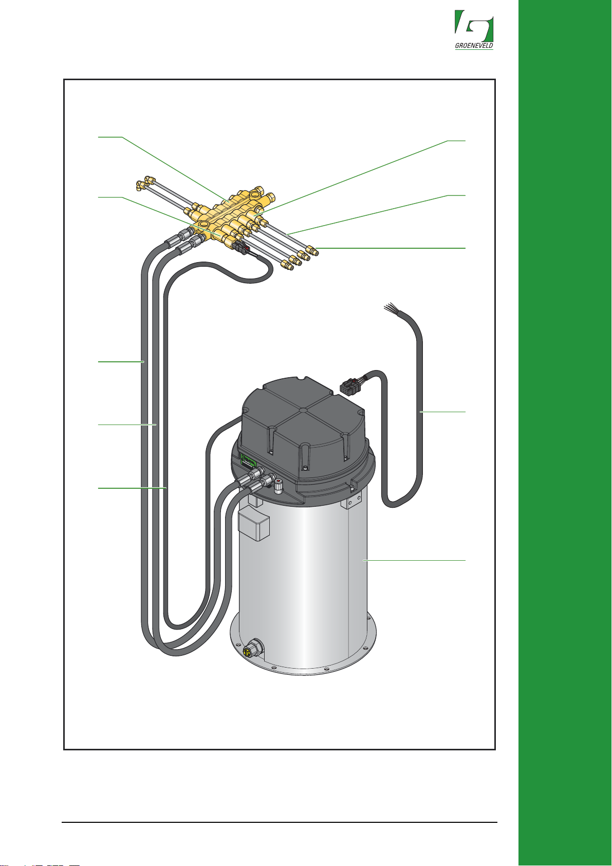
Beschrijving (fig. A)
Een Groeneveld Twin-3 vetsmeersysteem bestaat doorgaans uit de volgende
onderdelen:
1. Electrische vatpomp
2. Kabelboom electrische vatpomp
3. Kabelboom vetdrukschakelaar
4. Hoofdleiding B
5. Hoofdleiding A
6. Vetdrukschakelaar
7. Doseurblok
8. Doseur
9. Secundaire leiding
10. Aansluitkoppeling op het smeerpunt
Als een Twin-3 vetsmeersysteem wordt gemonteerd op een voertuig dat
bestuurd wordt door een PLC (Programmable Logic Controller), kan de
besturing van het Twin-3 vetsmeersysteem eventueel worden overgenomen
door die PLC. In dat geval zal de electrische vatpomp worden geleverd zonder
besturingseenheid.
Voor een uitgebreide beschrijving van het complete Twin-3 vetsmeersysteem
verwijzen we u naar de Algemene Handleiding Twin-3.
F210613 rev.00
Page 7

7
Werking van de Twin-3 elektrische vatpomp (fig. A & B)
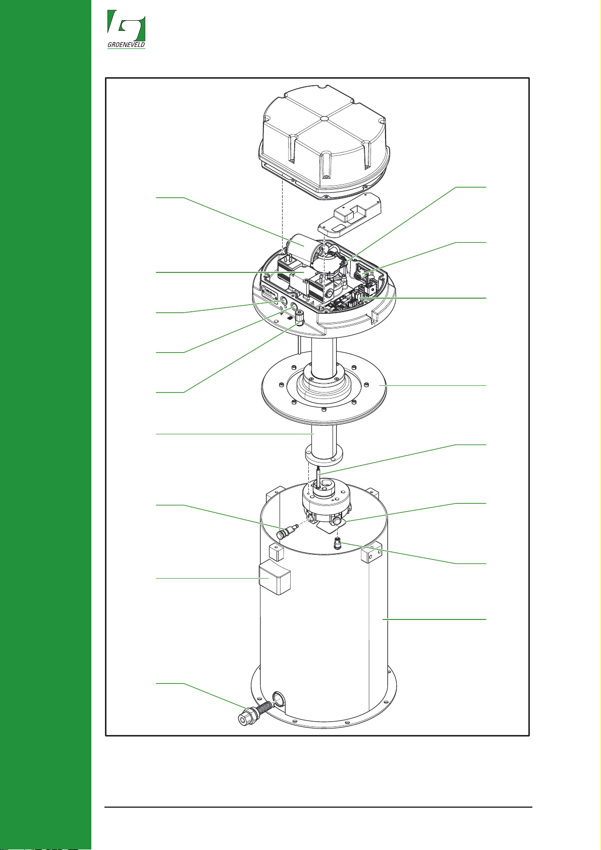
Het hart van de vatpomp wordt gevormd door een elektrisch aangedreven
pompunit die bestaat uit een 5-tal radiaal geplaatste vaste cilinders met zuigers
(25). Een elektromotor (19) drijft, via een mechanische overbrenging een as aan
met een daarop bevestigd excentriek. Dit excentriek beweegt de vijf zuigers (25)
heen en weer, die het vet via de vetkanalen naar het vetsmeersysteem pompen.
Behalve het excentriek drijft dezelfde as een roerwerk (13) aan dat zich onder
de pompunit bevindt. Het vet wordt hiermee door naar boven gestuwd. Tussen
de vetkanalen bevindt zich een drukoverstortklep (12), die ervoor zorgt dat de
vetdruk de 250 bar niet overschrijdt.
Bovenin de vatpomp bevindt zich een elektronische besturingseenheid (16),
elektromotor (19) en een 5/2-weg ventiel met twee magneetspoelen (20). Aan
het begin van een smeercyclus activeert de besturingseenheid één van de twee
magneetspoelen en start vervolgens de elektromotor (19). Het vet wordt uit het
vat via het 5/2-weg ventiel naar het hoofdleidingkanaal A (21) of B (22) gepompt.
De stand van dit 5/2-weg ventiel bepaald naar welke primaire vetleiding (4 of 5)
het wordt gepompt. Tijdens deze zogenaamde pompfase neemt de vetdruk in
de primaire vetleiding toe. In een doseurblok (7) is een vetdrukschakelaar (6)
gemonteerd, die een signaal aan de besturingseenheid (16) geeft als een vooraf
ingestelde vetdruk waarde is bereikt. De pomp stopt, maar de primaire vetleiding
blijft door het 5/2-weg ventiel wel op druk, omdat de magneetspoel bekrachtigt
blijft. De periode dat de primaire vetleiding nog op druk wordt gehouden, is een
instelbaar percentage van de periode waarin is gepompt; dit noemen we de
‘nasmeerfase’.
1. GEBRUIKSAANWIJZING
Aan het einde van deze 'nasmeerfase' wordt het 5/2-weg ventiel geopend door
de bekrachtige magneetspoel te deactiveren en de andere magneetspoel te
activeren. Het vet kan uit de primaire vetleiding terugstromen naar het vat,
waardoor de druk zal afbouwen ‘drukafbouwfase’. Na de ‘drukafbouwfase’ wordt
de magneetspoel gedeactiveerd. De ‘drukafbouwfase’ is even lang als de
‘nasmeerfase’. De resterende tijd van deze cyclus wordt gebruikt voor een
‘pauzefase’ tussen twee cycli. Pas daarna volgt een volgende cyclus, maar nu
in de andere primaire vetleiding.
Boven het vet bevindt zich een volgzuiger (15). Als het vetniveau daalt, zakt de
volgzuiger mee onder invloed van zijn eigen gewicht. De volgzuiger sluit de toetreding van lucht en condensatiewater uit en voorkomt daarmee:
• Oxidatie van het vet.
• Vermenging van het vet met condensatiewater.
• Verzeping van het vet.
De minimumniveauschakelaar (14) bewaakt het vetniveau in het vat. Bereikt het
vet het minimale niveau, dan meldt de minimumniveauschakelaar dat aan de
besturingseenheid (16).
F210613 rev.00
Page 8

8
1. GEBRUIKSAANWIJZING
Werking van de testdrukknop (fig. B)
Inleiding
Om het smeersysteem te testen kunnen twee verschillende testcycli worden
uitgevoerd met de testdrukknop (18):
1. de enkele-testcyclus (via de A- of B-vetleiding)
2. de continu-testcyclus (een aantal opeenvolgende smeercycli via de
A- en B-vetleiding)
Een testcyclus kan alleen worden uitgevoerd als het vetsmeersysteem met de
nasmeerfase, de drukafbouwfase of met de pauzefase bezig is. Als het systeem
bezig is met een pompfase reageert het niet op de testdrukknop.
Als zich storingen voordoen tijdens een testcyclus, zal de signaallamp of LED dit
op de gebruikelijke wijze aangeven.
De testcycli tellen niet mee voor de statistiek, die de besturingseenheid bijhoudt.
Deze gegevens tellen niet mee, omdat de gegevens een vertekend beeld geven
van de werkelijke prestaties van het vetsmeersysteem.
LET OP
Gebruik de testcycli alleen als het nodig is. Elke keer dat een
testcyclus wordt uitgevoerd, wordt vet aan de smeerpunten
toegevoegd. Dit kost vet en kan leiden tot overmatig smering van de
smeerpunten.
De enkele testcyclus
Handel als volgt om een enkele-testcyclus uit te voeren:
1. Zet het contact aan.
2. Druk op de testdrukknop (18), tenminste twee seconden maar niet
langer dan zes seconden.
De enkele-testcyclus zal nu worden gestart. De signaallamp of LED zal tijdens
de hele smeercyclus knipperen. Als een storing optreedt, zal het knipperen van
de lamp of LED overgaan in een storingsmelding.
De enkele-testcyclus eindigt na de drukafbouwfase of als het contact wordt
uitgezet. Als het contact weer wordt aangezet zal het programma altijd beginnen
met de pauzefase van de zojuist beëindigde of afgebroken cyclus.
LET OP
Bedenk dat een enkele-testcyclus slechts één van de primaire
vetleidingen (pompuitgangen) betrekt in de test. Als u het systeem
ook via de andere primaire vetleiding wilt testen, moet u een tweede
enkele testcyclus uitvoeren.
F210613 rev.00
Page 9

9
De continu testcyclus
Met een continu-testcyclus kunt u versneld extra vet toevoegen aan de
smeerpunten of het smeersysteem ontluchten.
LET OP
Bij extreem koud weer kan het voorkomen dat het vetsmeersysteem
faalt om de continu-testcyclus correct uit te voeren. Gebruik in dit
geval de enkele-testcyclus.
Voer als volgt een continu-testcyclus uit:
1. Zet het contact aan.
2. Druk op de testdrukknop (18) langer dan zes seconden.
Het systeem zal een pompfase starten. Nadat pompfase A is beëindigd, start
onmiddellijk een pompfase B, dan A weer, dan B, enzovoort. De pauzefases
worden steeds overgeslagen.
De signaallamp of LED zal gedurende de hele test knipperen. Als een storing optreedt, zal het knipperen van de signaallamp of LED overgaan in een
alarmsignaal.
1. GEBRUIKSAANWIJZING
3. Zet het contact uit om de continu-testcyclus te beëindigen.
Als het contact weer wordt aangezet zal het programma altijd beginnen met de
pauzefase van de zojuist beëindigde of afgebroken pompfase.
F210613 rev.00
Page 10

10
1. GEBRUIKSAANWIJZING
Controle van werking van de pomp en 5/2-weg ventiel
(fig. A & B)
1. Koppel beide primaire vetleidingen (4 en 5) los van de Twin-3 vatpomp.
LET OP
Er kan nog vetdruk in een van deze primaire vetleidingen aanwezig
zijn.
2. Monteer een manometer op beide vetuitgangen (21 en 22).
3. Druk de testdrukknop (18) ongeveer vier seconden in om een testcyclus te starten. De pomp pompt nu vet uit een van de vetkanalen. De
manometer gekoppeld aan dit kanaal moet nu snel oplopen tot de
maximum bereikbare druk van tussen de 230 en 250 bar.
LET OP
De pomp wordt niet gestopt door de vetdrukschakelaar (6), omdat
het systeem afgekoppeld is.
Indien de pomp deze druk niet haalt, heeft dit de volgende oorzaken:
• Luchtinsluiting in het vet (luchtbellen). Verwijder de manometers van
beide vetkanalen A en B en laat het vet uitstromen tot er geen
luchtbellen meer meekomen. Vul het vat eventueel met een kleine
hoeveelheid olie rondom de pompunit om de lucht rond de pompunit
te verdrijven.
• Vet is te dik. Daardoor wordt het niet aangezogen door de
pompzuigers. Vervang het vet in het vat en in de primaire
vetleidingen.
• Pomp is defect. Vervang of repareer de pomp.
4. Beëindig de testcyclus door het contact uit te schakelen of de T win-3
connector (17) even los en weer aan te koppelen.
5. Start weer een testcyclus met de testdrukknop.
De pomp moet nu in het tweede kanaal starten en de manometer zal
snel oplopen tot de maximum ingestelde vetdruk van tussen 230 en
250 bar. Het eerste kanaal zal drukloos worden.
Wanneer de druk in het eerste kanaal niet afgebouwd wordt en ook geen druk
in het nieuwe kanaal opgebouwd wordt, is het 5/2-weg ventiel (20) defect.
Vervang het 5/2-weg ventiel.
6. Beëindig de testcyclus door het contact uit te schakelen of de T win-3
connector even los en weer aan te koppelen.
F210613 rev.00
Page 11
11
Bijvullen van het vet (fig. B)
Gebruik van het juiste smeermiddel
WAARSCHUWING
Het is van het grootste belang dat het juiste smeermiddel wordt
gebruikt in het Twin-3 vetsmeersysteem. Raadpleeg de
onderhoudsboeken van het voertuig, zoals opgesteld door de
fabrikant van het voertuig. Raadpleeg uw vetleverancier of
Groeneveld als u een ander type vet wilt gaan gebruiken.
Het Twin-3 vetsmeersysteem is ontwikkeld voor gebruik van vetten tot en met
NLGI-klasse 2.
Welke NLGI-klasse moet worden toegepast, is hoofdzakelijk afhankelijk van de
temperaturen waaronder het vetsmeersysteem moet werken:
1. GEBRUIKSAANWIJZING
Laagste
werktemperatuur
Hoogste
werktemperatuur
Gebruik
NLGI-klasse
-20°C (-4°F) +70°C (+160°F) 2
<-20°C (-4°F) +70°C (+160°F) Synthetisch 2
<-20°C (-4°F) 0°C (+32°F) 0 / 1
Vaste toevoegingen in het vet (bijv. teflon (PFTE) en grafiet) kunnen op termijn
tot blokkades in het vetsmeersysteem leiden. Wij raden dan ook af om dergelijke
vetten in het vetsmeersysteem te gebruiken. Vet met molybdeendisulfide
(MoS2) mag alleen worden gebruikt als het vet van top kwaliteit is en niet meer
dan 5% MoS2 bevat.
F210613 rev.00
Page 12

12
1. GEBRUIKSAANWIJZING
Bijvullen van het vet
Als het vet in het vat het minimumniveau heeft bereikt, moet het vat worden
bijgevuld. Het vat is hiervoor uitgerust met een vulkoppeling (27) waarop een
vulpomp kan worden aangesloten.
De vulprocedure is als volgt:
1. Pers bij een nieuwe vulpomp (of vulslang) eerst de vulslang vol met
vet. Dit voorkomt dat lucht wordt mee gepompt in het vat.
2. Verwijder de stofkap van de vulkoppeling.
3. Reinig de vulkoppeling en de koppeling op de vulslang zorgvuldig.
4. Zet de vulslang vast op de vulkoppeling.
5. Vul het buitenvat tot aan het maximumniveau. Het maximumniveau
is bereikt zodra de rode stift van de vetindicator (23) ±1,5 cm naar
buiten is gedrukt. Tijdens het vullen ontsnapt de lucht boven de volgzuiger via het ontluchtingsopening (26) aan de zijkant van het vat.
6. Ontkoppel de vulslang en breng de stofkap aan op de vulkoppeling.
7. Plaats de vulslang terug op de vulkoppeling, die bovenop het vetdrumdeksel van de vulpomp is gemonteerd.
LET OP
De vatpomp valt in storing als de pomp éénmaal geen vetdruk heeft
opgebouwd in combinatie met een minimumniveaumelding. Deze
storing kan worden opgeheven door het vet in het vat bij te vullen.
Tevens moet de besturingseenheid gereset worden. Doe dit door
één seconde op de testknop van de vatpomp te drukken met
ingeschakeld contact.
Reiniging en onderhoud
De elektrische vatpomp vergt geen speciaal onderhoud.
• Reinig regelmatig de buitenzijde van de elektrische vatpomp.
• Reinig of verwissel eens per jaar het filter achter de vulkoppeling
(27) in het vat.
F210613 rev.00
Page 13

13
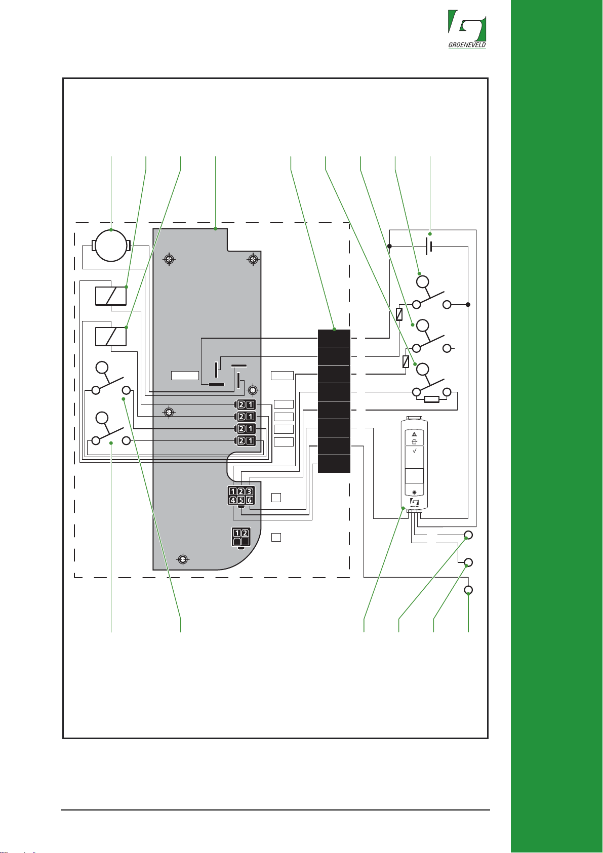
Electrisch schema (fig. C)
a. Elektromotor
b. Magneetspoel 1, 5/2-weg ventiel
c. Magneetspoel 2, 5/2-weg ventiel
d. Besturingseenheid
e. Pompconnector
f. Vetdrukschakelaar
g. Extra schakelaar
h. Contactschakelaar
i. Accu
j. Testdrukknop
k. Minimuniveauschakelaar
l. Twin-3 display
m. Foutsignaaluitgang (max. 6W), -31 massa
n. Minimumniveau signaaluitgang (max. 6W), -31 massa
o. Extra in-en uitgangsaansluiting
Technische specificaties
1. GEBRUIKSAANWIJZING
Afmetingen l x b x h: 340 x 340 x 656 mm
V oedingsspanning: 24 Vdc
Vetopbrengst: 20 cc bij 20°C
Maximale vetdruk: 250 bar
Inhoud vat: 18 liter
Stroomafname: 4A bij 20°C / 15A bij -20°C
Gewicht (zonder vet): 23 Kg
Werktemperatuur: -20°C .... +70°C
Type goedkeuring overeenkomstig
de volgende richtlijnen:
Beschermingsklasse: IP67 (pompunit)
F210613 rev.00
Page 14

14
1. USER’S INSTRUCTION
Foreword
This User’s Instruction contains a specification of the Twin-3 electric drum pump.
This information is intended to give the user an insight into the procedures to be
used for the use and maintenance of the Twin-3 electric drum pump. This User’s
Instruction also contains the technical specifications of the various components
of the Twin-3 electric drum pump.
The following symbols in this User’s Instruction draw the user's attention to
specific points, or emphasize a warning:
ATTENTION
Draws the user's attention to important supplementary information
that will avoid problems.
WARNING
Warns the user of incorrect actions that could result in personal
injury or serious damage to the system.
Specification (fig. A)
A Groeneveld Twin-3 greasing system is usually comprised of the following
components:
1. Electrical drum pump
2. Cable harness electrical drum pump
3. Cable harness grease pressure switch
4. Main grease line B
5. Main grease line A
6. Grease pressure switch
7. Metering block
8. Metering unit
9. Secondary grease line
10. Coupling on the grease point
If so required, Twin-3 greasing systems fitted to vehicles controlled by a PLC
(Programmable Logic Controller) can be controlled by the PLC. In such
instances the Twin-3 electrical drum pump will be supplied without a control unit.
Please refer to the Twin-3 General Manual for a comprehensive specification of
the Twin-3 greasing system.
F210613 rev.00
Page 15

15
Operation of the Twin-3 electric drum pump (fig. A & B)
The heart of the drum pump is formed by an electric pump unit comprised of 5
fixed cylinders (25) in a radial array. An electric motor (19) connected to the shaft
by a mechanical transmission drives the excentric on the shaft. This excentric
moves the five cylinders (25) backwards and forwards, thereby pumping the
grease to the greasing system via the grease channels. In addition to driving the
excentric, this same shaft drives a mixer (13) under the pump unit. This mixer
forces the grease upwards. A pressure-relief valve (12) fitted between the
grease channels prevents the pressure of the grease exceeding 250 bar.
The drum pump contains an electronic control unit (16) and a 5/2-way valve with
two coils (20). The electronic control unit activates one of the 5/2-way valve coil
and starts the pump at the beginning of a greasing cycle. The grease is pumped
via the 5/2-way valve to the main grease lines. The position of this 5/2-way valve
determines which main grease line (21 or 22) is supplied with grease. The
grease pressure in the main grease line increases during this 'pumping phase'.
A grease-pressure switch (6) fitted to the metering block (7) transmits a signal to
the electronic control unit once a set pressure is attained. This stops the pump;
however the 5/2-way valve maintains the pressure in the main grease line,
because the coil is still activated. The period during which the pressure is
maintained in the main grease line can be set at a percentage of the pumping
period; this period is referred to as the 'retaining phase'.
1. USER’S INSTRUCTION
The 5/2-way valve is opened at the end of this 'retaining phase', by de-activating
the powered coil and activing the other coil, to allow the grease to flow back into
the drum and allow the pressure to fall during the 'pressure release phase’. The
remaining time in the cycle is used as a 'pause phase' between two cycles. The
next cycle will begin after this 'pause phase', when grease will be supplied to the
other main grease line.
A follower plate (15) prevents air from coming into contact with the grease. As
the level of grease falls the sealing plunger sinks under its own weight, thereby
retaining the seal. The sealing plunger prevents the ingress of air and
condensation, thereby avoiding:
• oxidation of the grease.
• water mixing with the grease.
• saponification of the grease.
The minimum-level switch (14) monitors the level of grease in the drum. The
minimum-level switch transmits a signal to the electronic control unit (16) when
the grease falls to the minimum level.
F210613 rev.00
Page 16

16
1. USER’S INSTRUCTION
Operation of the test pushbutton (fig. B)
Introduction
The test pushbutton (18) is used to start one of two different test cycles to check
the performance of the greasing system, i.e.:
1. a single-test cycle (via the A or B grease line).
2. a continuous-test cycle (a number of successive greasing cycles via
the A and B grease lines).
Test cycles can be initiated only when the greasing system is in the follow-on
greasing phase, pressure-drop phase, or pause phase. The system will not
respond to the test pushbutton in the pumping phase.
The warning light or LED illuminates in the event of any malfunctions during a
test cycle.
These test cycles are not included in the log maintained by the electronic control
unit. The test data is not included since this data would give a biased indication
of the greasing system's actual performance.
ATTENTION
Use the test cycles only when necessary. Each test cycle supplies
grease to the greasing points. This uses additional grease, and can
result in the over-lubrication of the greasing points.
The single-test cycle
The procedure for a single-test cycle is as follows:
1. Turn the key in the ignition switch.
2. Press the test push button (18) for at least 2 seconds, but no longer
than 6 seconds.
The single-test cycle will now begin. The indicator light or LED will flash
throughout the greasing cycle. The flashing light or LED will switch to alarm
mode in the event of a malfunction.
The single-test cycle is terminated after the pressure-drop phase, or on turning
the key in the ignition switch. On turning the key in the ignition switch again the
program will always begin with the pause phase of the cycle that has just been
completed or interrupted.
ATTENTION
It is important to remember that a single-test cycle will test only one
of the main grease lines (pump discharge lines). If you also wish to
test the other main grease line then you will need carry out a second
single-test cycle.
F210613 rev.00
Page 17

17
The continual-test cycle
The continual-test cycle enables you to rapidly supply extra grease to the
greasing points or to purge the greasing system.
ATTENTION
The greasing system may be unable to carry out the continual-test
cycle correctly in extremely cold weather. In such situations you
should use the single-test cycle.
The procedure for a continual-test cycle is as follows:
1. Turn the key in the ignition switch.
2. Press the test push button (18) for longer than 6 seconds.
The system will initiate a pumping phase. On the conclusion of pumping phase
A the system will immediately begin pumping phase B, followed by pumping
phase A, etc. The pause phases are skipped. The pressure in one main grease
line will fall whilst the other is being brought to pressure.
1. USER’S INSTRUCTION
The indicator light or LED will flash throughout the test. The flashing light or LED
will switch to alarm mode in the event of a malfunction.
3. Turn the key in the ignition switch to terminate the continual-test
cycle.
On turning the key in the ignition switch again the program will always begin with
the pumping phase of the cycle that has just been completed or interrupted.
F210613 rev.00
Page 18

18
1. USER’S INSTRUCTION
Inspection of the operation of the pump and the 5/2way valve (fig. A & B)
1. Disconnect both main greasing lines (4 and 5) from the Twin-3 drum
pump.
ATTENTION
One of these main grease lines may still be under pressure.
2. Connect a manometer on the A and B outlets (21 and 22).
3. Press the test push button (18) for about 4 seconds to start a test
cycle. The pump will now pump grease to one of these outlets. The
pressure indicated by the manometer fitted to this outlet must now
rapidly increase to the maximum attainable pressure of between 230
and 250 bar.
ATTENTION
The pump will not be stopped by the grease-pressure switch (6),
since this switch is disconnected.
The pump's failure to attain this pressure can be due to the following causes:
• Air entrapped in the grease (air bubbles). Remove the manometers
on the outlets A and B and allow the grease to flow from the outlets
until no more air is seen. If so required, add a little oil in the drum
around the pump unit to expel the air around the pump unit.
• The grease is too viscous, as a result of which the pump plungers
are unable to draw the grease into the system. Replace the grease in
the drum and the main grease lines.
• The pump is defective. Repair or replace the pump.
4. Stop the test cycle by turning the key in the ignition switch or by
briefly detaching the Twin-3 connector (17).
5. Begin a new test cycle by pressing the test push button. The pump
should now supply grease to the second outlet and the pressure indicated by the manometer will rapidly increase to the maximum set
grease pressure of between 230 and 250 bar. The first outlet will be
at atmospheric pressure.
If the pressure in the first outlet does not fall and the second outlet is not brought
to pressure then the 5/2-way valve (20) is defective. Replace the 5/2-way valve.
6. Stop the test cycle by turning the key in the ignition switch or by
briefly detaching the Twin-3 connector.
F210613 rev.00
Page 19
19
Topping up the grease (fig.B)
Use the correct grease
WARNING
You must use the correct grease in the Twin-3 greasing system.
Consult the vehicle's maintenance books supplier by the vehicle's
manufacturer. Consult your grease supplier or Groeneveld if you
wish to change to a different type of grease.
The Twin-3 greasing system has been designed for use with greases up to and
including NLGI Category 2.
The appropriate NLGI category will primarily depend on the temperatures in
which the greasing system will operate:
1. USER’S INSTRUCTION
Lowest operating
temperature
Highest operating
temperature
Appropriate NLGI
category
-20°C (-4°F) +70°C (+160°F) 2
<-20°C (-4°F) +70°C (+160°F) Synthetic 2
<-20°C (-4°F) 0°C (+32°F) 0 / 1
Additives (such as Teflon (PFTE) or graphite) in the grease can ultimately result
in blockages in the greasing system. Consequently we recommend you avoid
using greases of this type in the greasing system. Grease containing
molybdenum disulphide (MoS2) may be used only when the grease is of high
quality and does not contain more than 5% MoS2.
F210613 rev.00
Page 20

20
1. USER’S INSTRUCTION
Topping up the grease
The level of grease in the refillable drum must be topped up once the level has
fallen to the minimum level. Top up the grease by connecting a filling pump to
the filling coupling (27) fitted to the drum.
The procedure used to fill the drum is as follows:
1. Begin by pumping the hose of a new filling pump (or filling hose) with
grease. This will prevent air from being pumped with the grease into
the drum.
2. Remove the dust cap from the filling coupling.
3. Carefully clean the filling coupling and the connection on the filling
hose.
4. Connect the filling hose to the filling coupling.
5. Fill the drum to the maximum level. The maximum level is reached
as soon the red pin of the fill indicator (23) is pushed out for ± 1,5 cm.
Whilst the drum is being filled the air above the follower plate will
escape via the breather duct (26) fitted to the side of the drum.
6. Disconnect the filling hose and fit the dust cap to the filling coupling.
7. Fit the filling hose to the filling coupling mounted on top of the grease
drum lid of the filling pump.
ATTENTION
The drum pump will switch to fail mode when the pump has failed
to attain the grease pressure and the minimum-level alarm has been
generated. This can be rectified by topping up the level of grease in
the refillable drum. It will also be necessary to reset the control unit.
Reset the control unit by turning the key in the ignition switch and
pressing the test push button for one second.
Cleaning and maintenance
No special maintenance of the electric drum pump is required.
• Clean the outside of the electric drum pump at regular intervals.
• Clean or replace the filter behind the filler coupling (27) of the
refillable drum once a year.
F210613 rev.00
Page 21

21
Electrical diagram (fig. C)
a. Electric motor
b. Coil 1, 5/2-way valve
c. Coil 2, 5/2-way valve
d. Electronic control unit
e. Connector pump
f. Grease pressure switch
g. Command switch
h. Ignition switch
i. Batterie
j. Test pushbutton
k. Minimum le vel switch
l. Twin-3 display
m. Error signal output (max. 6W), -31 ground
n. Minimum level signal output (max. 6W), -31 ground
o. Additional in- output connection
Technical specifications
1. USER’S INSTRUCTION
Sizes l x b x h: 340 x 340 x 656 mm
Power supply: 24 Vdc
Grease output: 20 cc at 20°C
Maximum grease pressure: 250 bar
Content drum: 18 litre
Power consumption: 4A at 20°C / 15A at -20°C
Weight (without grease): 23 Kg
Operating temperature: -20°C .... +70°C
T ype of approval in accordance with
the following directives:
Protection class: IP67 (pump unit)
F210613 rev.00
Page 22

Groeneveld Transport Efficiency B.V., Stephensonweg 12, 4207 HB Gorinchem, P.O. Box 777, 4200 AT Gorinchem,
The Netherlands, Ph : +31 183 641 400, F : +31 183 624 474, http://www.groeneveld-group.com
 Loading...