

Page 1
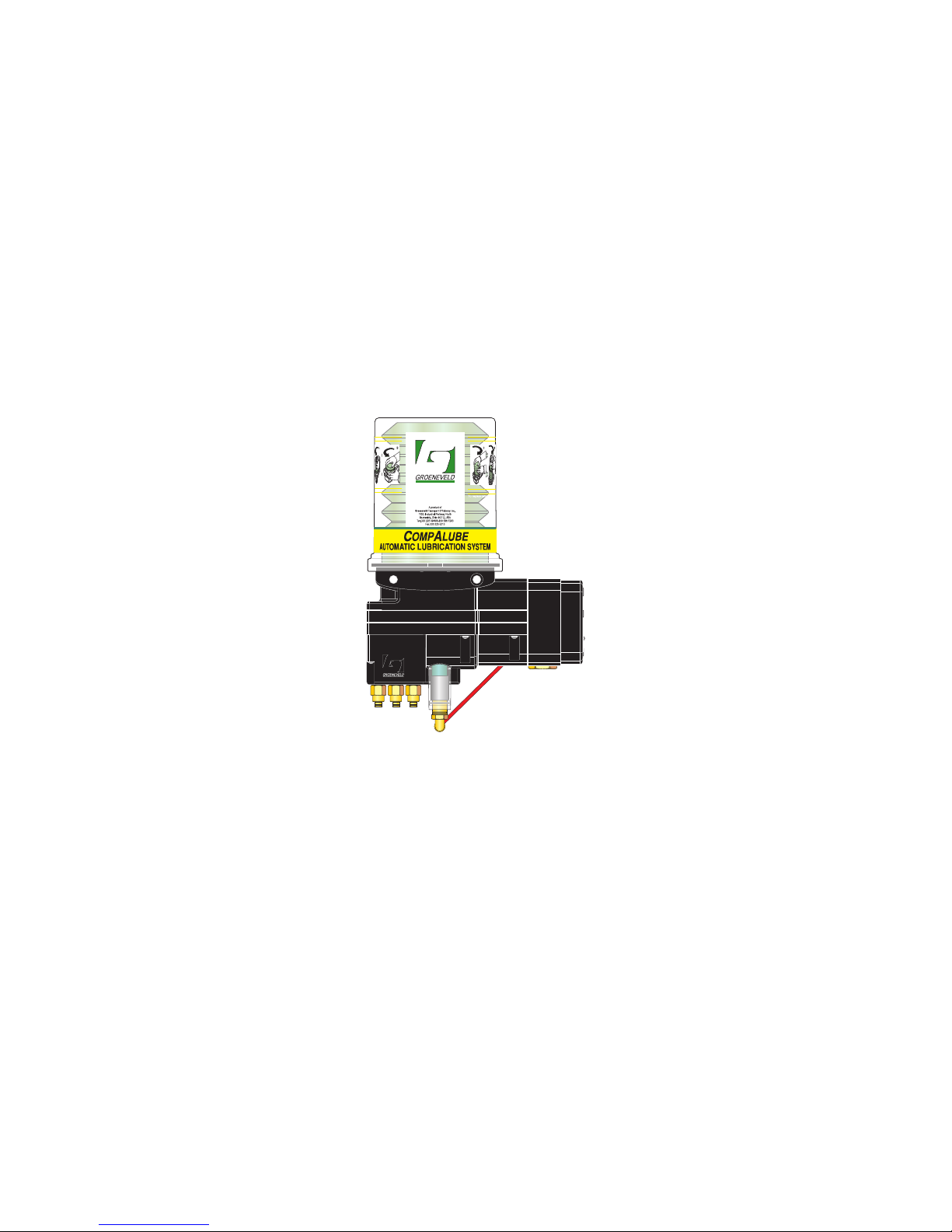
General Manual
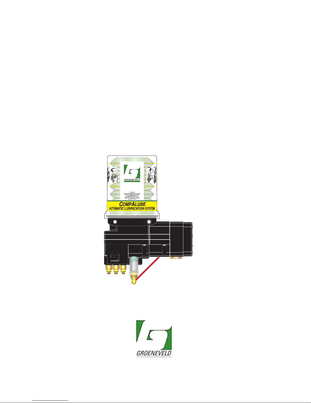
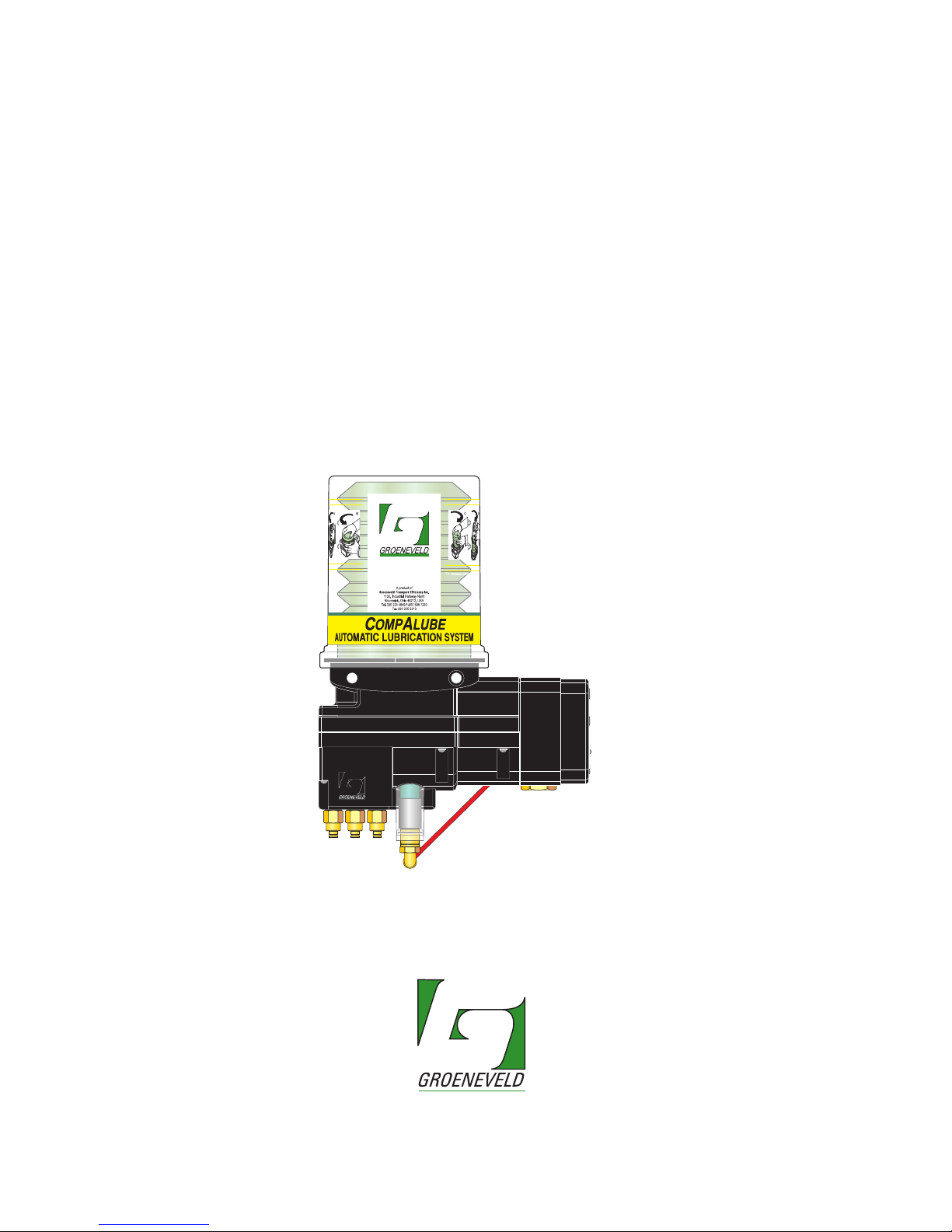
CompAlube
Automatic greasing system
EG0105P02
your efficiency is our challenge
Page 2

General information
Type of manual General Manual
System CompAlube Automatic greasing system
Manual number EG0105P02
Publication date September 2005
Revision 02
All rights reserved. No part of this manual may be copied and/or published by means of printing, photocopying,
microfilm or by any other means without prior written permission from Groeneveld. This applies also to the
drawings and diagrams appended.
Groeneveld reserves the right to change parts at any time, without prior or direct notice to the customer. The
contents of this manual may also be changed without prior notice.
This manual applies to the standard version of the product. Groeneveld cannot accept liability for any damage
arising from the use of specifications other than that supplied.
You are requested to contact Groeneveld technical service for information concerning adjustment, maintenance
work or repairs that is not described in this manual.
Whilst this manual has been prepared with the greatest possible care Groeneveld cannot accept responsibility for
any errors of the concequences of such errors.
Page 3

CompAlube Automatic greasing system
Table of contents
3
Publication date: September 2005
EG0105P02
Foreword - - - - - - - - - - - - - - - - - - - - - - - - - - - - - - - - - - - - - - - - - - - 5
1. Introduction - - - - - - - - - - - - - - - - - - - - - - - - - - - - - - - - - - - - - - - - - 7
1.1. Introduction - - - - - - - - - - - - - - - - - - - - - - - - - - - - - - - - - - - - - - - - - - - - 8
1.2. Groeneveld Transport Efficiency B.V. - - - - - - - - - - - - - - - - - - - - - - - - - - 8
1.3. Groeneveld greasing systems - - - - - - - - - - - - - - - - - - - - - - - - - - - - - - - - 9
1.4. Operation - - - - - - - - - - - - - - - - - - - - - - - - - - - - - - - - - - - - - - - - - - - - - - 9
2. System description - - - - - - - - - - - - - - - - - - - - - - - - - - - - - - - - - - - 11
2.1. Introduction - - - - - - - - - - - - - - - - - - - - - - - - - - - - - - - - - - - - - - - - - - - 12
2.2. Main components - - - - - - - - - - - - - - - - - - - - - - - - - - - - - - - - - - - - - - - 12
2.3. The CompAlube pump unit - - - - - - - - - - - - - - - - - - - - - - - - - - - - - - - - 14
2.3.1. Pneumatic CompAlube with brake-counter - - - - - - - - - - - - - 14
2.3.2. Pneumatic CompAlube with integrated electronic timer - - - 15
2.3.3. Pneumatic CompAlube with integrated electronic timer - - - 16
3. Operation - - - - - - - - - - - - - - - - - - - - - - - - - - - - - - - - - - - - - - - - - - 17
3.1. Introduction - - - - - - - - - - - - - - - - - - - - - - - - - - - - - - - - - - - - - - - - - - - 18
3.2. Control unit - - - - - - - - - - - - - - - - - - - - - - - - - - - - - - - - - - - - - - - - - - - 18
3.2.1. CompAlube with brake-counter - - - - - - - - - - - - - - - - - - - - - 18
3.2.2. CompAlube with electronic timer - - - - - - - - - - - - - - - - - - - - 18
3.3. Pump - - - - - - - - - - - - - - - - - - - - - - - - - - - - - - - - - - - - - - - - - - - - - - - - 19
3.3.1. Plunger pump - - - - - - - - - - - - - - - - - - - - - - - - - - - - - - - - - - - 19
3.3.2. Gear pump - - - - - - - - - - - - - - - - - - - - - - - - - - - - - - - - - - - - - 20
3.4. Metering units - - - - - - - - - - - - - - - - - - - - - - - - - - - - - - - - - - - - - - - - - 21
3.4.1. Introduction - - - - - - - - - - - - - - - - - - - - - - - - - - - - - - - - - - - - 21
3.4.2. Operation - - - - - - - - - - - - - - - - - - - - - - - - - - - - - - - - - - - - - - 21
3.5. Monitoring - - - - - - - - - - - - - - - - - - - - - - - - - - - - - - - - - - - - - - - - - - - - 23
3.5.1. Grease-pressure indicator - - - - - - - - - - - - - - - - - - - - - - - - - - 23
3.5.2. Grease-pressure switch - - - - - - - - - - - - - - - - - - - - - - - - - - - - 24
3.6. Test cycle - - - - - - - - - - - - - - - - - - - - - - - - - - - - - - - - - - - - - - - - - - - - - 24
4. Operation - - - - - - - - - - - - - - - - - - - - - - - - - - - - - - - - - - - - - - - - - - 25
4.1. Introduction - - - - - - - - - - - - - - - - - - - - - - - - - - - - - - - - - - - - - - - - - - - 26
4.2. Performing a test cycle - - - - - - - - - - - - - - - - - - - - - - - - - - - - - - - - - - - 26
4.2.1. Pneumatic CompAlube with brake-counter - - - - - - - - - - - - - 26
4.2.2. Pneumatic CompAlube with electronic timer - - - - - - - - - - - - 27
4.2.3. Electrical CompAlube with electronic timer - - - - - - - - - - - - - 27
4.3. Replacing the grease cartridge - - - - - - - - - - - - - - - - - - - - - - - - - - - - - 28
4.4. Refilling through the filling connection - - - - - - - - - - - - - - - - - - - - - - - 31
4.5. Setting the greasing interval - - - - - - - - - - - - - - - - - - - - - - - - - - - - - - - 32
4.5.1. CompAlube with brake-counter - - - - - - - - - - - - - - - - - - - - - 32
4.5.2. CompAlube with electronic timer - - - - - - - - - - - - - - - - - - - - 32
4.6. Venting - - - - - - - - - - - - - - - - - - - - - - - - - - - - - - - - - - - - - - - - - - - - - - 32
1. q^_ib=lc=`lkqbkqp
Page 4

Table of contents4
Publication date: September 2005
CompAlube Automatic greasing system
EG0105P02
5. Installation - - - - - - - - - - - - - - - - - - - - - - - - - - - - - - - - - - - - - - - - -33
5.1. Introduction - - - - - - - - - - - - - - - - - - - - - - - - - - - - - - - - - - - - - - - - - - - 34
5.2. General installation instructions - - - - - - - - - - - - - - - - - - - - - - - - - - - - - 34
5.3. Safety precautions - - - - - - - - - - - - - - - - - - - - - - - - - - - - - - - - - - - - - - - 35
5.4. Installation of the CompAlube pump unit - - - - - - - - - - - - - - - - - - - - - 36
5.4.1. The CompAlube pump unit - - - - - - - - - - - - - - - - - - - - - - - - - 36
5.4.2. Fitting the pump on the vehicle - - - - - - - - - - - - - - - - - - - - - - 36
5.5. Grease lines and couplings - - - - - - - - - - - - - - - - - - - - - - - - - - - - - - - - - 37
5.5.1. Fitting the grease lines and couplings - - - - - - - - - - - - - - - - - 38
5.5.2. Maximum grease line length - - - - - - - - - - - - - - - - - - - - - - - - 39
5.6. Pneumatic lines - - - - - - - - - - - - - - - - - - - - - - - - - - - - - - - - - - - - - - - - - 40
5.6.1. Pneumatic CompAlube with brake-counter - - - - - - - - - - - - - 40
5.6.2. Pneumatic CompAlube with electronic timer - - - - - - - - - - - - 41
5.7. Electrical cables - - - - - - - - - - - - - - - - - - - - - - - - - - - - - - - - - - - - - - - - - 42
5.7.1. The pneumatic CompAlube with electronic timer - - - - - - - - - 42
5.7.2. The electrical CompAlube with electronic timer - - - - - - - - - - 42
5.8. CompAlube for lorries - - - - - - - - - - - - - - - - - - - - - - - - - - - - - - - - - - - - 42
5.8.1. Pneumatic CompAlube with integrated brake-counter - - - - - 42
5.9. Venting - - - - - - - - - - - - - - - - - - - - - - - - - - - - - - - - - - - - - - - - - - - - - - - 43
5.9.1. The pneumatic CompAlube with brake-counter - - - - - - - - - - 43
5.9.2. The CompAlube with electronic timer - - - - - - - - - - - - - - - - - 44
5.9.3. Grease lines - - - - - - - - - - - - - - - - - - - - - - - - - - - - - - - - - - - - - 44
5.10. Putting into service - - - - - - - - - - - - - - - - - - - - - - - - - - - - - - - - - - - - - - 45
5.10.1. The pneumatic CompAlube with brake-counter - - - - - - - - - - 45
5.10.2. The pneumatic CompAlube with electronic timer - - - - - - - - - 47
5.10.3. The electrical CompAlube with electronic timer - - - - - - - - - - 48
6. Maintenance - - - - - - - - - - - - - - - - - - - - - - - - - - - - - - - - - - - - - - - - 51
6.1. Introduction - - - - - - - - - - - - - - - - - - - - - - - - - - - - - - - - - - - - - - - - - - - 52
6.2. Periodic check - - - - - - - - - - - - - - - - - - - - - - - - - - - - - - - - - - - - - - - - - - 52
6.3. Trouble shooting - - - - - - - - - - - - - - - - - - - - - - - - - - - - - - - - - - - - - - - - 53
6.3.1. Pneumatic CompAlube malfunctions - - - - - - - - - - - - - - - - - - 53
6.3.2. Electrical CompAlube malfunctions - - - - - - - - - - - - - - - - - - - 54
7. Technical specifications - - - - - - - - - - - - - - - - - - - - - - - - - - - - - - - -55
7.1. Pump - - - - - - - - - - - - - - - - - - - - - - - - - - - - - - - - - - - - - - - - - - - - - - - - - 56
7.2. Metering units - - - - - - - - - - - - - - - - - - - - - - - - - - - - - - - - - - - - - - - - - - 57
7.3. Maximum grease line length - - - - - - - - - - - - - - - - - - - - - - - - - - - - - - - 57
7.4. Brake-counter (pneumatic CompAlube) - - - - - - - - - - - - - - - - - - - - - - - 57
7.5. Electronic timer (pneumatic CompAlube) - - - - - - - - - - - - - - - - - - - - - - 57
7.6. Electronic timer (electrical CompAlube) - - - - - - - - - - - - - - - - - - - - - - - 57
7.7. Control lamp - - - - - - - - - - - - - - - - - - - - - - - - - - - - - - - - - - - - - - - - - - - 57
7.8. Pump dimensions - - - - - - - - - - - - - - - - - - - - - - - - - - - - - - - - - - - - - - - - 58
Page 5
CompAlube Automatic greasing system
Foreword
5
Publication date: September 2005
EG0105P02
1. FOREWORD
your efficiency is our challenge
Page 6

Foreword6
Publication date: September 2005
CompAlube Automatic greasing system
EG0105P02
This system manual contains a description of the CompAlube automatic greasing
system. The intention is to give potential customers an insight into how the system
works, what the possibilities are and, in brief, the maintenance aspects. In addition,
this manual contains the technical data of the different parts of the greasing
system. The system manual can also be used as user manual.
The manual comprises different sections, indicated with a chapter number. The
numbering of the illustrations starts anew at the beginning of each chapter.
Chapter 1, the introduction gives a description of Groeneveld and greasing systems
in general.
Chapter 2 describes the complete CompAlube greasing system.
Chapter 3 gives an insight into the operation of the system components.
In chapter 4, the operation of the greasing system is treated.
In chapter 5, the installation of the system is treated.
Maintenance is treated in chapter 6.
The manual concludes with chapter 7, which contains the technical specifications
of the CompAlube greasing system.
The folllowing pictograms are used in this manual to notify or warn the user:
Caution:
Notifies the user about important supplementary information, with the
purpose of avoiding problems.
WARNING
Warns the user if there is a danger of bodily injury or serious damage to the
equipment through incorrect actions/operation.
Page 7
CompAlube Automatic greasing system
Introduction
7
Publication date: September 2005
EG0105P02
1.
1. INTRODUCTION
your efficiency is our challenge
Page 8
Introduction8
Publication date: September 2005
CompAlube Automatic greasing system
EG0105P02
1.1 Introduction
This chapter contains a brief presentation of the Groeneveld Transport Efficiency
company and the products that we supply. In addition, a description of the
CompAlube Automatic greasing system is given.
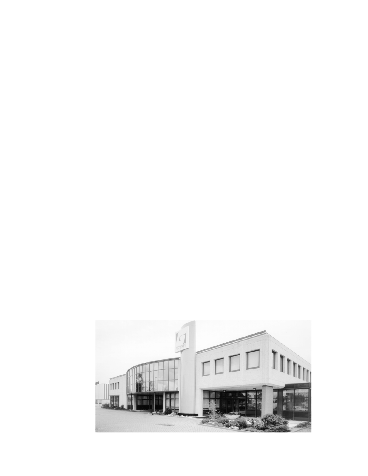
1.2 GROENEVELD Transport Efficiency B.V.
Investing in reliability. Groeneveld was established in 1971 with just that in mind.
In the meantime, this has resulted in an international network of companies,
governed from the head office in Gorinchem, The Netherlands. Groeneveld strives
continuously to strengthen its already predominant position, which has been
obtained through a solid image and customer-oriented approach.
The people at Groeneveld form a team that works with great enthousiasm to
please its customers. A high level of automation allows rapid reactions. The ISO
9001 standard forms the basis for the guaranteed qualitiy of Groeneveld's
products. Frequent contact with all business relations and an elaborate dealer
network are the warranty for the good name of Groeneveld. We know what
today's entrepreneurs need: not an off-the-shelf product, but a customised
solution for the automation of the daily maintenance.
New technologies create new applications. This is why Groeneveld has an ample
budget for research and development to create new cost-effective products.
Groeneveld's Research and Development organisation co-operates closely with
leading R&D organisations and manufacturers of vehicles and machines.
Besides the CompAlube Automatic greasing system, Groeneveld supplies products
such as:
• temperature recording sytems
• on-board computer systems
• speed limiters
• automatic oil-level controllers
• reversing protection systems
Groeneveld supplies a complete range of cost-effective and comfort-enhancing
products.
Figure 1.1 The head office of Groeneveld
Page 9

CompAlube Automatic greasing system
Introduction
9
Publication date: September 2005
EG0105P02
1.3 Groeneveld greasing systems
Groeneveld's automatic greasing systems takes care of the daily maintenance of
everything that has moving parts. They prevent unnecessary wear and down-time
and thus costs and annoyance. Groeneveld greasing systems are applied, for
example, in: manufacturing, machines for civil engineering, agriculture, ships, the
off-shore industry and the transport industry.
The most important advantages:
• longer maintenance intervals; less unnecessary down-time.
• reduced wear of the greased parts, as a result of accurate and constant
greasing.
• lower repair and replacement costs.
• less unexpected down-time; less loss of production.
1.4 Operation
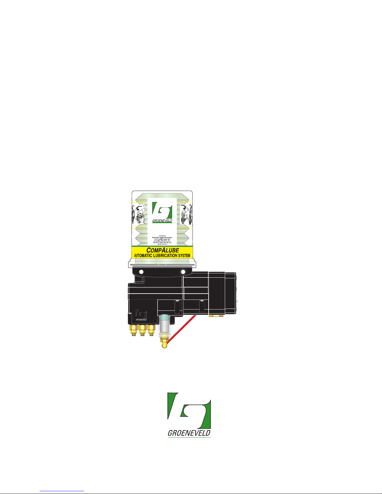
With CompAlube automatic greasing system from Groeneveld, all lubrication
points of a vehicle or machine are automatically lubricated at the right moment
and with the right amount of grease. Moreover, an optimum grease distribution is
obtained over the whole surface to be greased, because the machine or vehicle is
greased while it is operational. All actions are automatically performed by the
system. The user only needs to make sure that the reservoir is periodically refilled
and that the system is inspected.
Groeneveld's automatic greasing systems are carefully designed and thoroughly
tested to guarantee a long and trouble-free service life, even under the heaviest
operating conditions.
Besides correct installation and the use of the prescribed type of grease, a periodic
check of the operation is a condition for the continued good functioning of the
system. This periodic check is easy to carry out and can be done together with the
usual maintenance. Partly through a careful choice of materials, the greasing
system itself is almost maintenance-free.
Page 10

Introduction10
Publication date: September 2005
CompAlube Automatic greasing system
EG0105P02
Notes
Page 11
CompAlube Automatic greasing system
System description
11
Publication date: September 2005
EG0105P02
2.
2
. SYSTEM DESCRIPTION
your efficiency is our challenge
Page 12
System description12
Publication date: September 2005
CompAlube Automatic greasing system
EG0105P02
2.1 Introduction
The Groeneveld CompAlube greasing system is specially developed for use on
vehicles with a maximum of 19 lubrication points that must be greased. It is easy to
install, requires almost no maintenance and is extemely reliable.
2.2 Main components
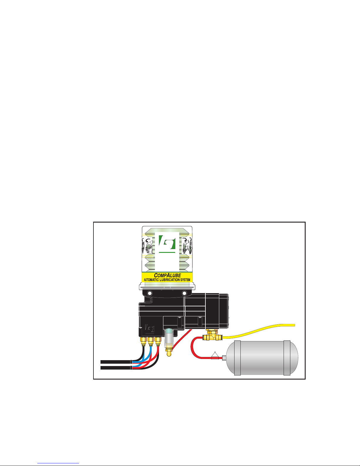
There are two versions of the CompAlube available: a pneumatic plunger pump
and an electrical gear pump.
A pneumatic CompAlube greasing system has the following components (Figure
2.1):
1. Pump unit with integrated:
• pneumatic grease pump (plunger pump)
• grease reservoir (grease cartridge)
• control unit (pneumatic brake-counter or electronic timer)
• metering units
• grease-pressure indicator
• filling connection (optional)
2. Grease lines from the metering units to the individual grease points.
3. Air lines to the pump.
4. Brake-counter, if installed.
5. Installation bracket for the pump (not shown).
Figure 2.1 Pneumatic CompAlube greasing system
GROENEVELD
GROENEVELD
A product of
Groeneveld Transport Efficiency Inc.
1130, Industrial Parkway North
Brunswick, Ohio 44212, USA
Tel. 330 225 4949/1-800 586 7283
Fax 330 225 5213
D
C
A
B
2
3
P
4
S
1
Gro_G0105_200
Page 13
CompAlube Automatic greasing system
System description
13
Publication date: September 2005
EG0105P02
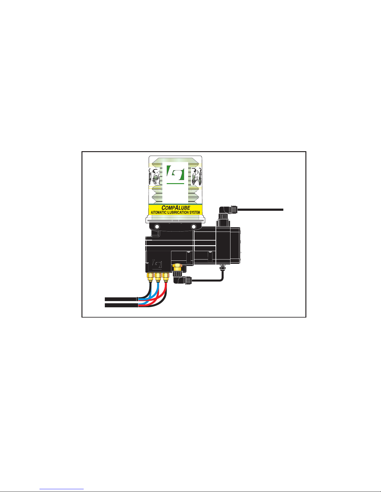
An electrical CompAlube greasing system has the following components (Figure
2.2):
1. Pump unit with integrated:
• electrical grease pump (gear pump)
• grease reservoir (grease cartridge)
• control unit (electronic timer)
• metering units
• grease-pressure sensor
• filling connection (optional)
2. Grease lines from the metering units to the individual grease points.
3. Electrical cable to the pump.
4. Installation bracket for the pump (not shown).
Figure 2.2 Electrical CompAlube greasing system
GROENEVELD
GROENEVELD
A product of
Groeneveld Transport Efficiency Inc.
1130, Industrial Parkway North
Brunswick, Ohio 44212, USA
Tel. 330 225 4949/1-800 586 7283
Fax 330 225 5213
D
C
A
B
2
3
1
Gro_G0105_201
Page 14
System description14
Publication date: September 2005
CompAlube Automatic greasing system
EG0105P02
2.3 The CompAlube pump unit
The pump unit is the heart of the CompAlube greasing system. It is a very compact
unit in which the most important components are integrated. The pump unit
requires virtually no maintenance and is easy to install and put into service.
Caution:
The automatic greasing system significantly reduces the time and effort
spent on manual greasing. However, do not forget that universal joints, for
instance, must still be greased by hand.
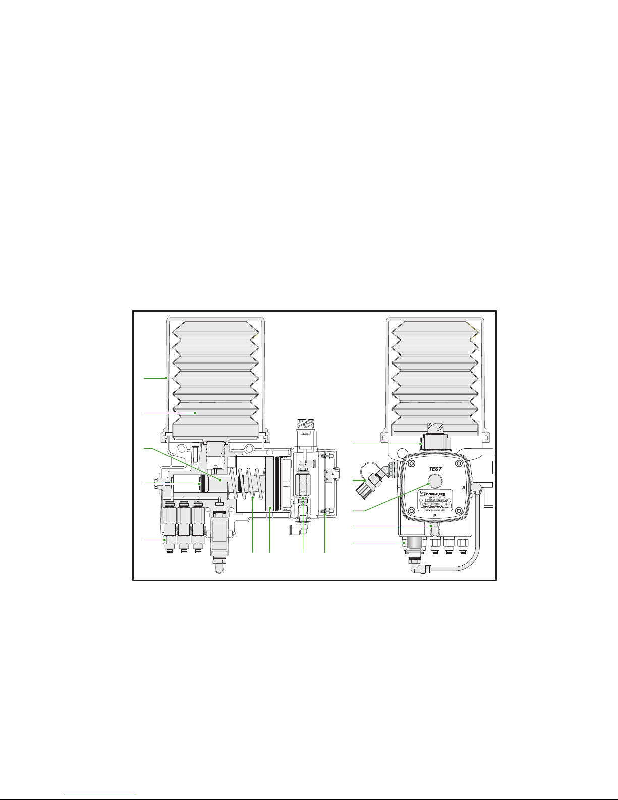
2.3.1 Pneumatic CompAlube with brake-counter
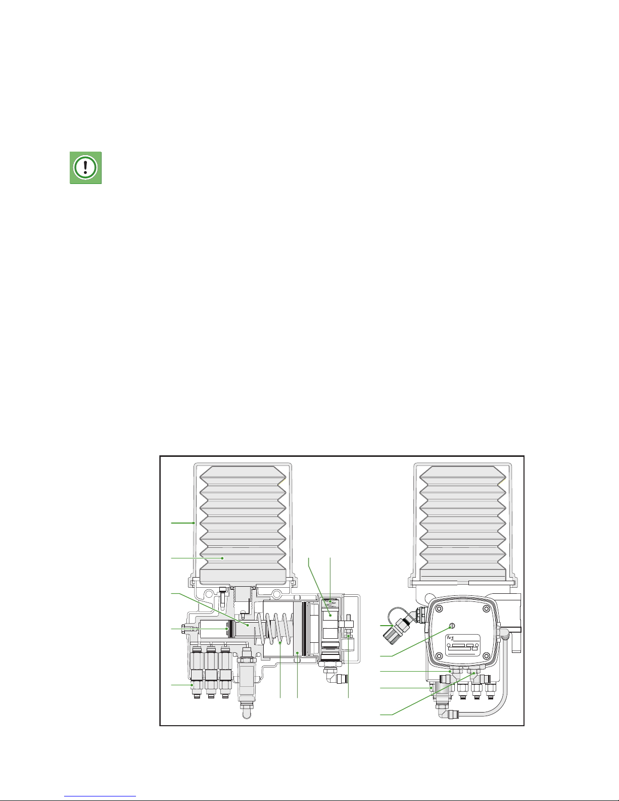
The pneumatic CompAlube pump unit with brake-counter has the following
components (Figure 2.3):
1. Transparent protection cover
2. Grease cartridge
3. Grease piston
4. Check valve
5. Metering units
6. Spring
7. Main air piston
8. Set screw
9. Control unit (pneumatic brake-counter)
10. Brake command air piston
11. Filling connection (optional)
12. Test screw (on brake-counter)
13. Compressed air connection (P)
14. Grease-pressure indicator
15. Brake command air connection (S)
Figure 2.3 Pneumatic CompAlube with brake-counter
PNEUMATIC PUMP
Type n c.c.
o
Groeneveld Transport Efficiency B.V.
Gorinchem, the Netherlands
Made by Groeneveld Italia s.r.l.(Lc)
PAS
Gro_G0105_202
2
109
6 7 8
3
11
13
12
15
14
4
5
1
Page 15
CompAlube Automatic greasing system
System description
15
Publication date: September 2005
EG0105P02
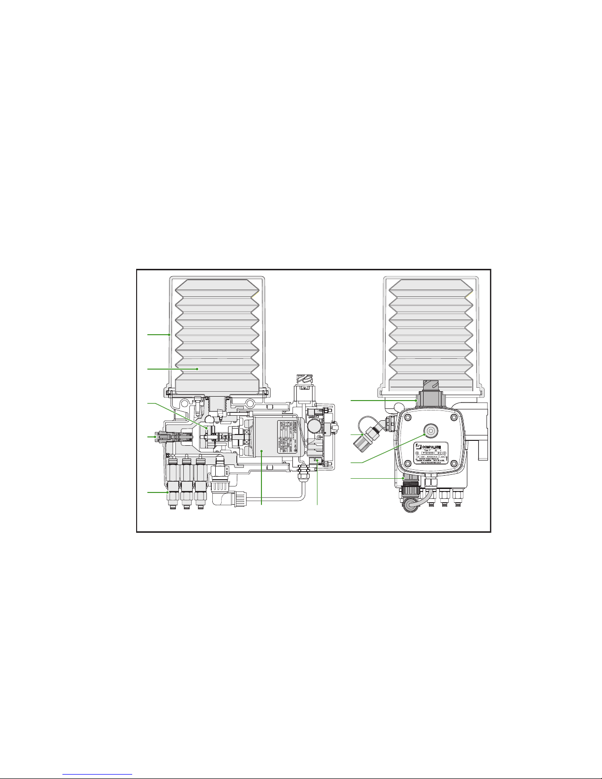
2.3.2 Pneumatic CompAlube with integrated electronic timer
The pneumatic CompAlube pump unit with integrated electronic timer has the
following components (Figure 2.4):
1. Transparent protection cover
2. Grease cartridge
3. Grease piston
4. Check valve
5. Metering units
6. Spring
7. Main air piston
8. Magnetic valve
9. Printed circuit board
10. Electrical connection
11. Filling connection (optional)
12. Test button
13. Compressed air connection (P)
14. Grease-pressure indicator
Figure 2.4 Pneumatic CompAlube with integrated electronic timer
Gro_G0105_203
2
6 798
3
11
13
12
14
10
4
5
1
Page 16
System description16
Publication date: September 2005
CompAlube Automatic greasing system
EG0105P02
2.3.3 Pneumatic CompAlube with integrated electronic timer
The electrical CompAlube pump unit with integrated electronic timer has the
following components (Figure 2.5):
1. Transparent protection cover
2. Grease cartridge
3. Gear pump
4. Pressure regulating valve
5. Metering units
6. Motor
7. Printed circuit board
8. Electrical connection
9. Filling connection (optional)
10. Test button
11. Grease-pressure switch
Figure 2.5 Electrical CompAlube with integrated electronic timer
Gro_G0105_204
2
6 7
3
9
8
11
10
4
5
1
Page 17
CompAlube Automatic greasing system
Operation
17
Publication date: September 2005
EG0105P02
3.
3. OPERATION
your efficiency is our challenge
Page 18

Operation18
Publication date: September 2005
CompAlube Automatic greasing system
EG0105P02
3.1 Introduction
This chapter contains a description of the operation of various components of the
Groeneveld CompAlube automatic greasing system. These are the control unit,
grease pump, metering units, grease-pressure indicator, grease-pressure switch and
the test screw or test button
.
3.2 Control unit
3.2.1 CompAlube with brake-counter
The Groeneveld CompAlube greasing system is controlled by a pneumatic brakecounter. This makes it particularly suited for vehicles that do not have a permanent
electrical power supply, such as (semi-)trailers.
The brake-counter draws the compressed air it needs from a protected air tank. The
counter is connected to the brake command air connection of the vehicle's braking
system through the fast-braking valve. This connection has a restriction, so that the
vehicle can always stop in the event of a fractured or broken line.
Each time that the brake-counter has registered a certain number of brake
applications (this number can be set), it starts the plunger pump and the greasing
system starts its greasing cycle.
The brake-counter contains a cam that rotates a few degrees if the brake command
air operates a piston in the brake-counter when the vehicle brakes. After the set
number of brake applications has been 'counted', the cam opens the integrated 3/
2 valve and the plunger pump is activated. (The pump phase starts.)
After a second series of brake applications (depending on the counter setting), the
cam closes the 3/2 valve again and the plunger pump stops. This is the end of the
pump phase and the greasing cycle.
3.2.2 CompAlube with electronic timer
When the CompAlube has an integrated electronic timer, the timer controls the
actions of the CompAlube greasing system. The timer is an electronically operated
device that is suited for vehicles that do not have a permanent electrical power
supply. With the electronic timer, you can set the duration (in minutes) of the
greasing interval.
Page 19
CompAlube Automatic greasing system
Operation
19
Publication date: September 2005
EG0105P02
3.3 Pump
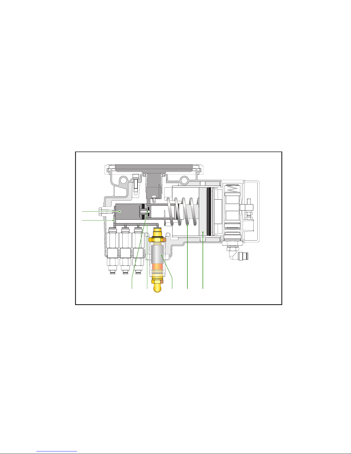
3.3.1 Plunger pump
When the brake-counter allows compressed air to flow from the air tank behind
the air/grease piston (Figure 3.1) of the plunger pump, this piston is pushed
sideways. The grease in chamber (2) is now placed under pressure, so that valve (3)
is pressed against the seat and the path to the grease reservoir is closed off (the
check valve). The grease now goes from chamber (2) through duct (4) to the grease
chamber (5) above the metering units. The metering units now apply the grease at
full pump pressure through the grease lines to the grease points. At the end of the
pump phase, the air pressure behind the air/grease piston (1) drops away and
spring (6) returns the piston to its starting position. At the same time, valve (3)
comes away from the seat and, as a result of the underpressure in chamber (2),
grease is sucked out of the grease cartridge.
Figure 3.1 Plunger pump
Gro_G0105_300
2
16753
4
Page 20
Operation20
Publication date: September 2005
CompAlube Automatic greasing system
EG0105P02
3.3.2 Gear pump
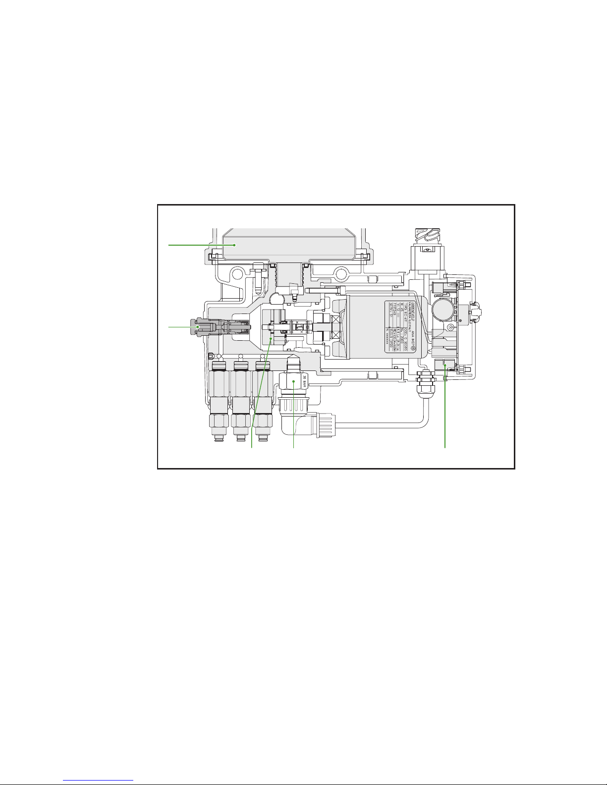
The gear pump (1) is switched on by the electronic time switch (2) (Figure 3.2). The
grease is now pumped from the reservoir (3) to the metering units. The pump
continues to run during the total cycle time. This cycle or pulse time is 2 minutes.
During the cycle, the pump builds the grease pressure up further all the time. At a
pressure of 55 bar, the pressure regulating valve (4) opens, and the grease returns
to the reservoir. The grease pressure is therefore limited to 55 bar.
After the greasing cycle of 2 minutes, the pump's direction of rotation is reversed
for 90 seconds, to release the pressure in the pump and metering units.
Figure 3.2 Gear pump
Gro_G0105_301
3
251
4
Page 21
CompAlube Automatic greasing system
Operation
21
Publication date: September 2005
EG0105P02
3.4 Metering units
3.4.1 Introduction
Nine different metering units can be supplied for the CompAlube pump; each with
a different grease output, varying from 0.025 cc to 1.0 cc per greasing cycle. By
carefully selecting the type of metering unit, each grease point will receive the
right amount of grease. The metering units are made of brass and, with their closed
construction, are extremely reliable.
3.4.2 Operation
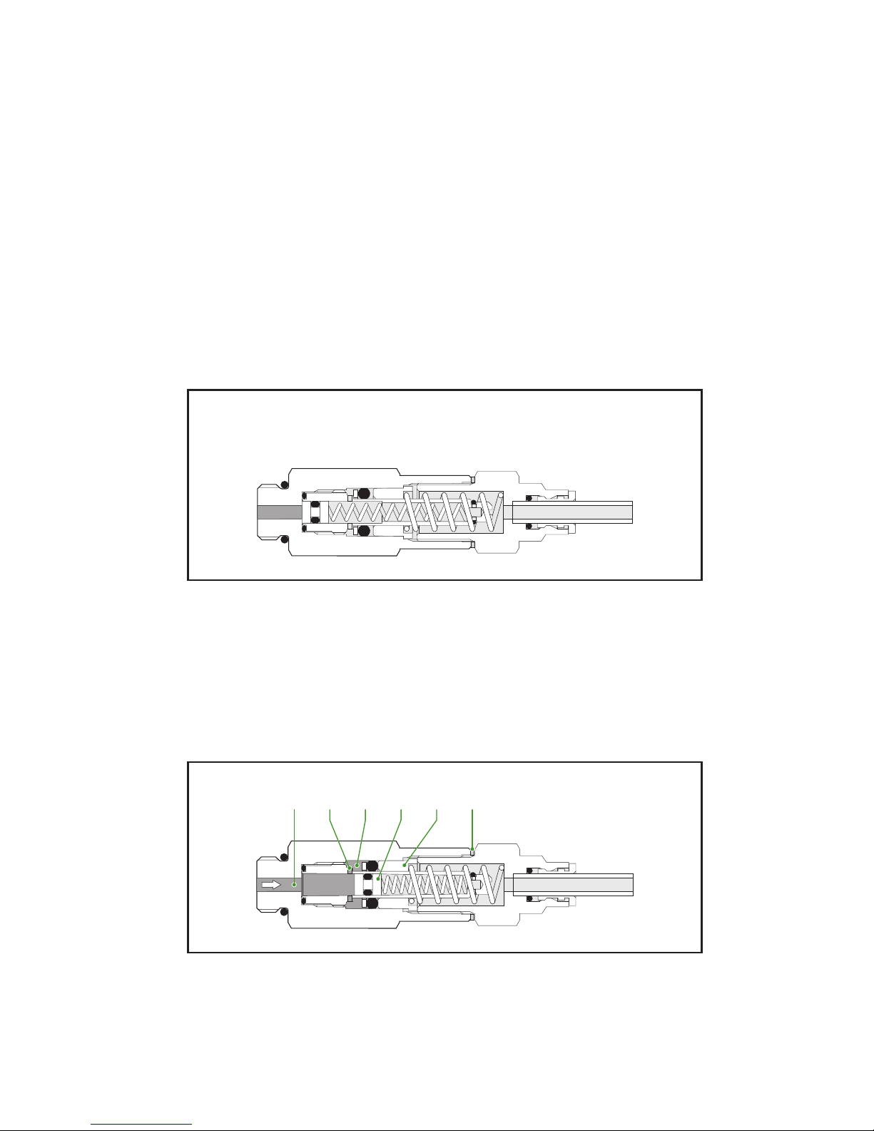
Phase A
For this explanation, we assume that we have a metering unit that is not yet filled
with grease at the beginning of the greasing cycle pump phase (Figure 3.3).
Figure 3.3 Phase A, metering unit in the starting position
Phase B
The pump presses the grease into channel (1) of the metering unit (Figure 3.4). The
pressure pushes plunger (4) past channel (2). The grease now fills chamber (3) and
pushes plunger (5) to the right. The stroke length of plunger (5) determines the
amount of grease that is pushed through the grease line to the grease point. This
stroke length - and thus the contents of chamber (3) - is determined by the total
thickness of the spacer(s) (6).
Figure 3.4 Phase B, metering unit during phase B
Gro_G0105_302
A
Gro_G0105_303
1 23456
B
Page 22
Operation22
Publication date: September 2005
CompAlube Automatic greasing system
EG0105P02
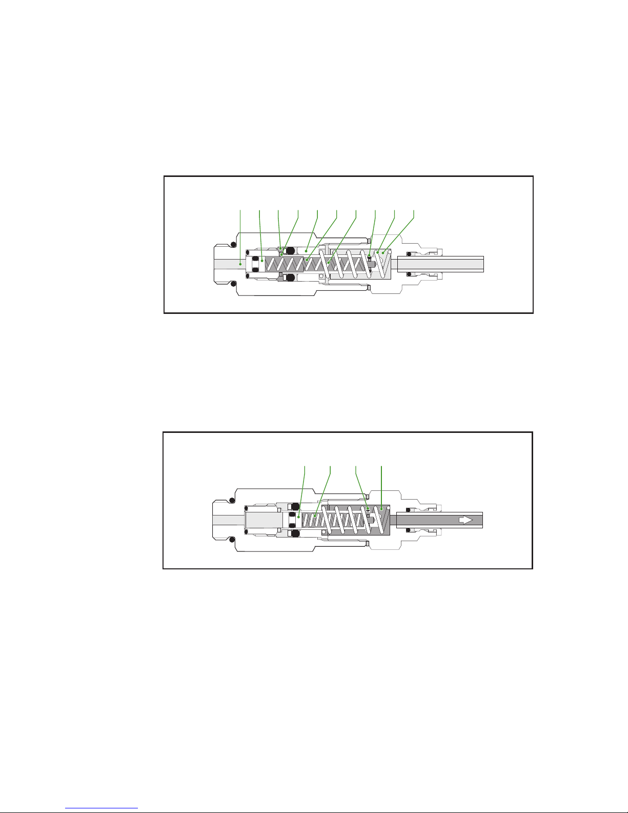
Phase C
When the pump stops and the grease pressure disappears, spring (8) pushes
plunger (4) back, to block channel (1) (Figure 3.5). O-ring (10) prevents the grease
in chamber (7) from being sucked back into the chamber. Spring (11) pushes
plunger (5) back, so that the grease in chamber (3) is transferred to chamber (9),
through channel (2).
Figure 3.5 Phase C, metering unit during phase C
Phase D
During the next greasing cycle, the same things happen as during phase B.
Chamber (9), however, is now filled with grease (Figure 3.6). When plunger (4) is
depressed, grease goes from chamber (9), through chamber (7) and the grease line,
to the grease point. O-ring (10) is pushed outwards, so that the grease can leave
chamber (9).
Figure 3.6 Phase D, metering unit during phase D
Gro_G0105_304
1 43259810 11 7
C
Gro_G0105_305
49107
D
Page 23
CompAlube Automatic greasing system
Operation
23
Publication date: September 2005
EG0105P02
3.5 Monitoring
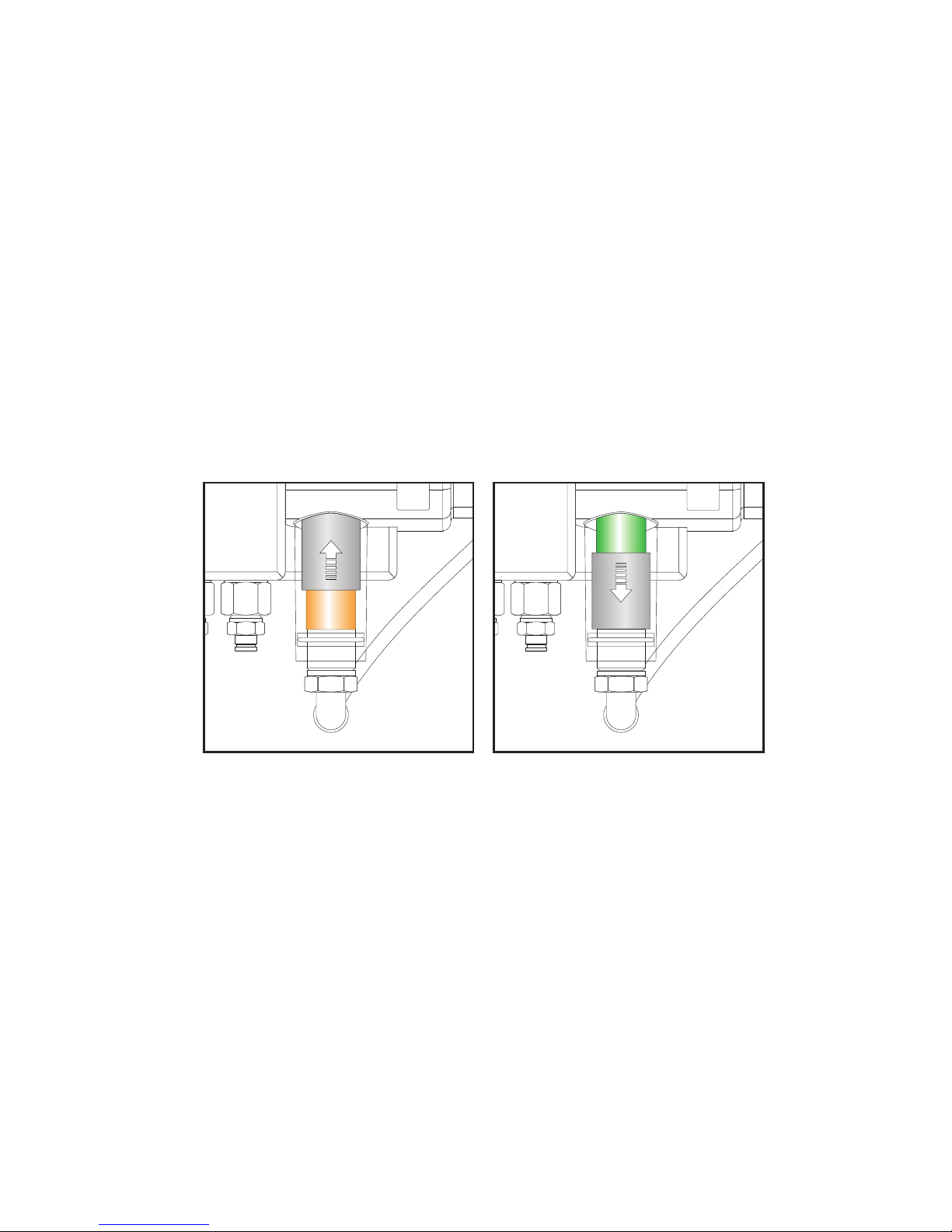
3.5.1 Grease-pressure indicator
The indicator warns the driver or maintenance personnel in the event of an empty
grease cartridge and incorrect functioning of the greasing system.
The moment that the brake-counter starts the plunger pump, compressed air also
flows under the piston in the grease-pressure indicator. The piston moves upwards
and a red indicator (Figure 3.7 left) can be seen behind the window. The chamber
on the other side of the piston is connected to the grease chamber above the
metering units. When grease pressure builds up in this chamber, the grease
pressure returns the grease-pressure indicator piston to its starting position. A
green indicator (Figure 3.7 right) appears in the window.
A green indicator therefore indicates that sufficient grease pressure was built up
during the last greasing cycle. A red indicator indicates that the necessary grease
pressure is not attained, which usually means that a grease cartridge is empty and
needs to be replaced.
Figure 3.7 Grease-pressure indicator
Gro_G0105_306
Page 24
Operation24
Publication date: September 2005
CompAlube Automatic greasing system
EG0105P02
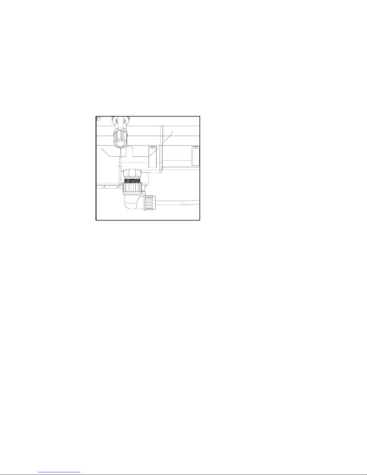
3.5.2 Grease-pressure switch
The pump has a grease-pressure switch to signal a too low pressure in the pump
during the greasing cycle (Figure 3.8).
This grease-pressure switch is depressed so far at 30 bar that an earth connection is
obtained. If this is not the case during the greasing cycle, because there is no or
insufficient grease pressure, the control lamp will light. The control lamp only goes
out at the next good greasing cycle or the contact on/off. When the contact is
switched on, the control lamp will light for 1 second.
Figure 3.8 Grease-pressure switch
3.6 Test cycle
By using the test screw (see paragraph 4.2.1) - which is on the brake-counter or on
the pushbutton (see paragraphs 4.2.2 and 4.2.3 ) of the electronic timer (on the
right-hand side of the pump unit) - the system can be tested and it is possible to
start an extra greasing cycle manually, to supply extra grease to the grease points.
This can also be used to vent the system after maintenance or repair work.
Gro_G0105_307
Page 25
CompAlube Automatic greasing system
Operation
25
Publication date: September 2005
EG0105P02
4.
4. OPERATION
your efficiency is our challenge
Page 26
Operation26
Publication date: September 2005
CompAlube Automatic greasing system
EG0105P02
4.1 Introduction
This chapter contains a description of how several components of the CompAlube
greasing system must be operated These are in turn performing a test cycle,
replacing the grease cartridge, refilling through the filling connection, setting the
greasing interval and venting.
4.2 Performing a test cycle
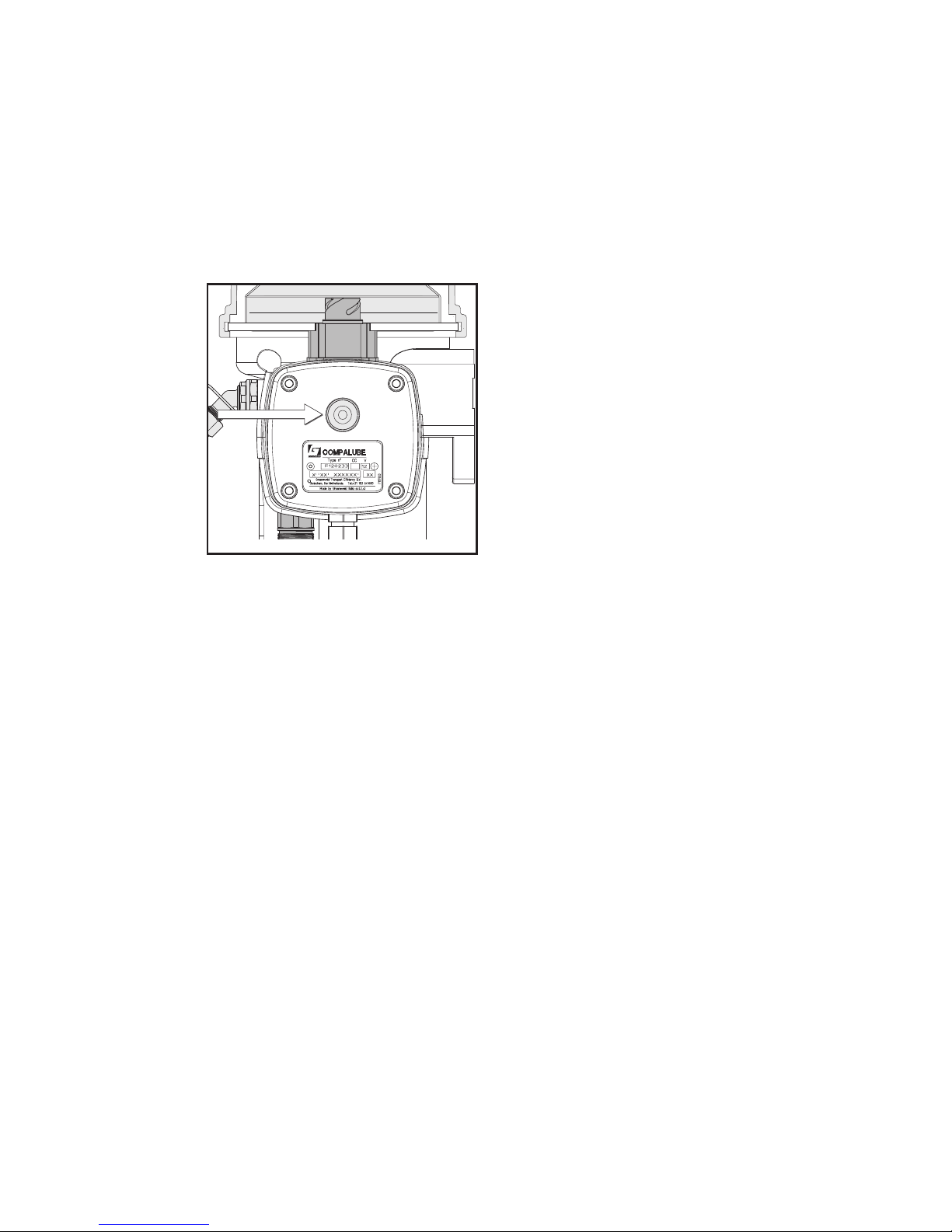
4.2.1 Pneumatic CompAlube with brake-counter
Place a flat screwdriver in the slot of the test screw. Push the test screw inward and
slowly turn the test screw anti-clockwise (Figure 4.1) until a greasing cycle is started
(when the greasing cycle starts, air will flow from the air tank into the pump, which
can be clearly heard).
The grease-pressure indicator will initially be red and almost immediately turn
green. Grease is now metered out to the grease points. Allow the greasing system
to operate for at least 30 seconds.
Caution!
There must be sufficient compressed air in the air tank to be able to perform
this test.
With the test screw, it is possible to quickly perform several greasing cycles in
succession. To do this, turn the test screw anti-clockwise for about 15 seconds after
starting the greasing cycle until the greasing cycle is finished (now, compressed air
will escape from the pump). Wait 15 seconds and start the procedure again. It is
important that you wait about 15 seconds between switching the pump on and off.
This time is needed for the metering units to recharge.
Figure 4.1 Test screw
PNEUMATIC PUMP
Type n c.c.
o
Groeneveld Transport Efficiency B.V.
Gorinchem, the Netherlands
Made by Groeneveld Italia s.r.l.(Lc)
Gro_G0105_400
Page 27
CompAlube Automatic greasing system
Operation
27
Publication date: September 2005
EG0105P02
4.2.2 Pneumatic CompAlube with electronic timer
Press the test button on the right-hand side of the pump unit (Figure 4.2) for a
minimum of three seconds but not longer than five seconds, until you hear
compressed air starting to flow to the pump. (If you press the test button for longer
than 5 seconds, you will start a multiple test cycle of 25 successive cycles that can be
used for greasing after repairs on the vehicle). This starts the pump procedure. This
lasts for 3 minutes. Wait 15 seconds before you start the next procedure.
Figure 4.2 Test button
4.2.3 Electrical CompAlube with electronic timer
Press the test button on the right-hand side of the pump unit (Figure 4.2) for a
minimum of three seconds but not longer than six seconds, until you hear that the
pump motor is switched on. (If you press the test button for longer than 6 seconds,
you will start a multiple test cycle of 10 successive cycles that can be used for
greasing after repairs on the vehicle). This starts the pump procedure. This lasts for
2 minutes. After these 2 minutes, the pump's direction of rotation is reversed for
90 seconds to release the grease pressure in the pump. Wait 15 seconds before you
start the next procedure.
Gro_G0105_401
Page 28
Operation28
Publication date: September 2005
CompAlube Automatic greasing system
EG0105P02
4.3 Replacing the grease cartridge
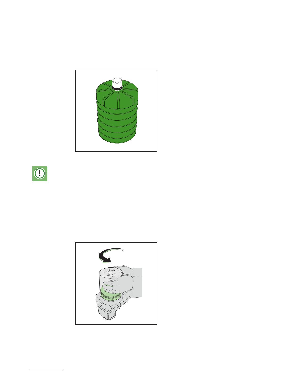
The CompAlube pump unit is fitted with a grease cartridge (Figure 4.3). The
cartridge is placed under a transparent protection cover and is easily and quickly
replaced:
Figure 4.3 Grease cartridge
Caution:
When replacing the grease cartridge, prevent dirt from entering the pump.
Before removing the protection cover and the cartridge, first clean the
pump and its immediate surroundings.
When removing a cartridge that is not completely empty, be aware that
grease can drip out of the cartridge. Protect the environment and prevent
grease spills.
Empty cartridges and grease residues must be disposed of in accordance
with local regulations.
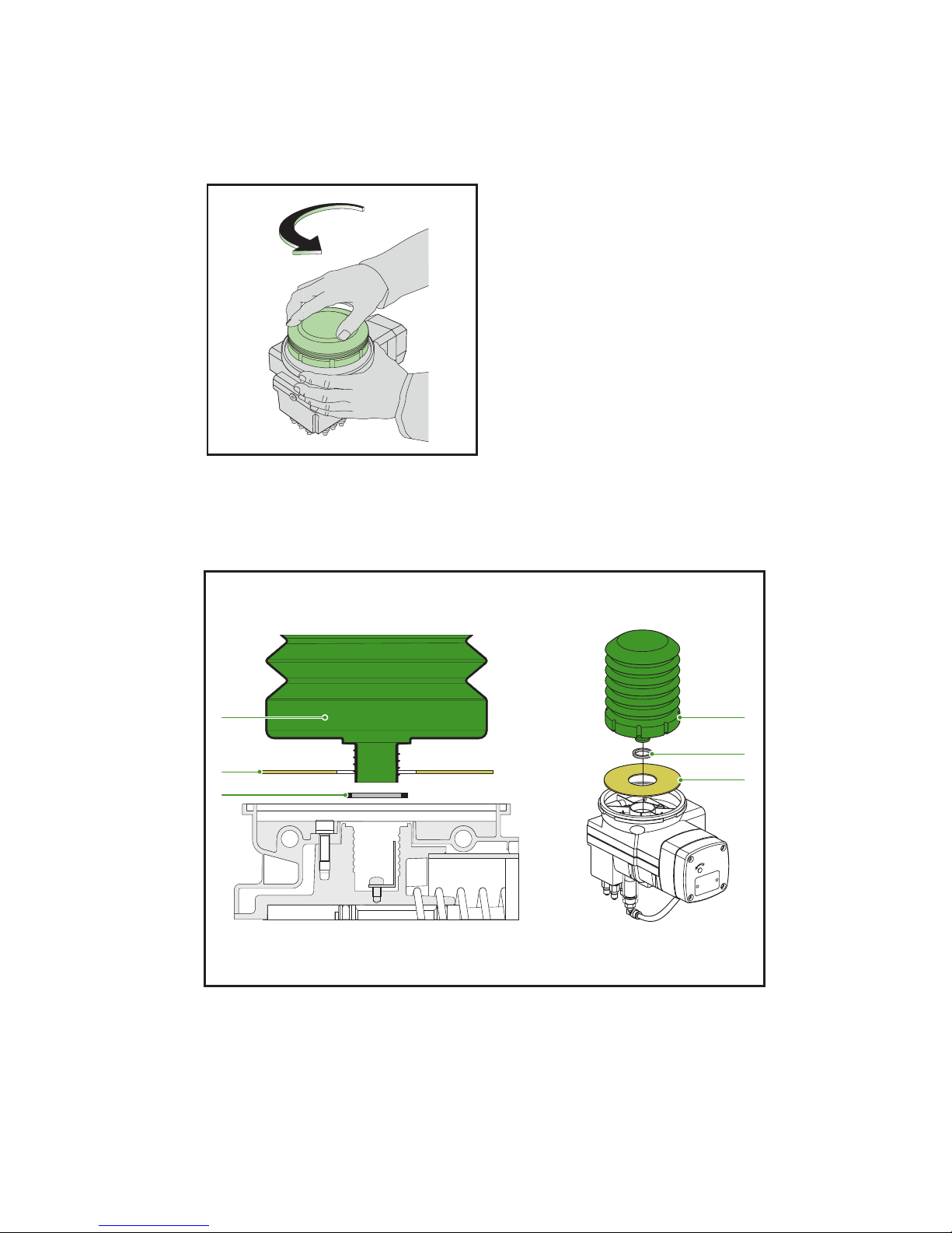
1. The transparent protection cover (Figure 4.4) has a bayonet catch. Turn the
cover anti-clockwise and lift it off the pump unit.
Figure 4.4 Removing the protection cover
Gro_G0105_402
Gro_G0105_403
Page 29
CompAlube Automatic greasing system
Operation
29
Publication date: September 2005
EG0105P02
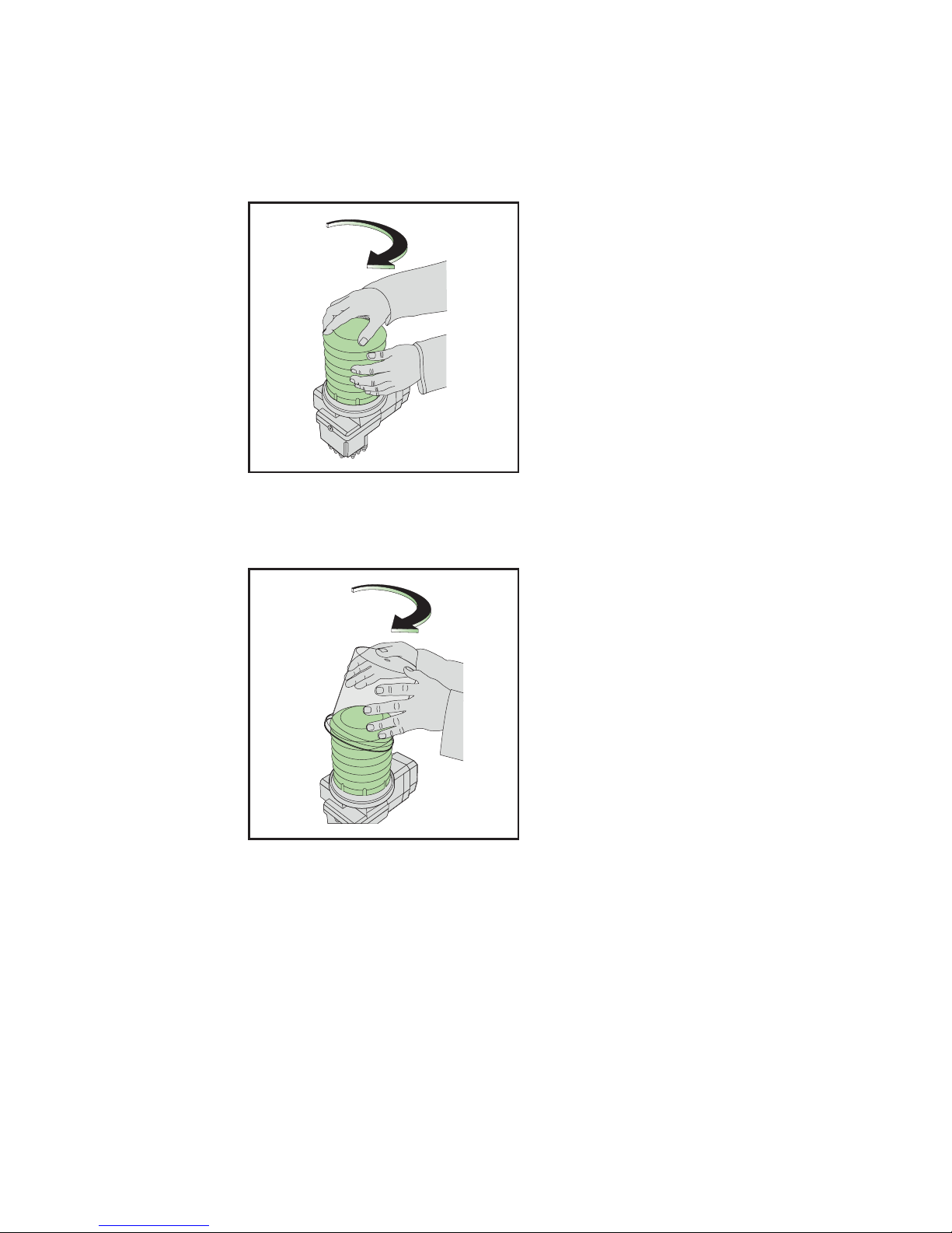
2. Remove the empty cartridge. The cartridge is screwed onto the pump. To
remove it, turn it anti-clockwise (Figure 4.5) and lift it straight up.
Figure 4.5 Removing the empty cartridge
3. Remove the rubber gasket (Figure 4.6.C) and the cardboard disc (Figure 4.6.B)
and replace them with the new parts, supplied with the new cartridge. Fit the
cartridge with only one rubber gasket.
Figure 4.6 Rubber gasket and cardboard disc
Gro_G0105_404
Gro_G0105_405
A
C
B
A
B
C
Page 30
Operation30
Publication date: September 2005
CompAlube Automatic greasing system
EG0105P02
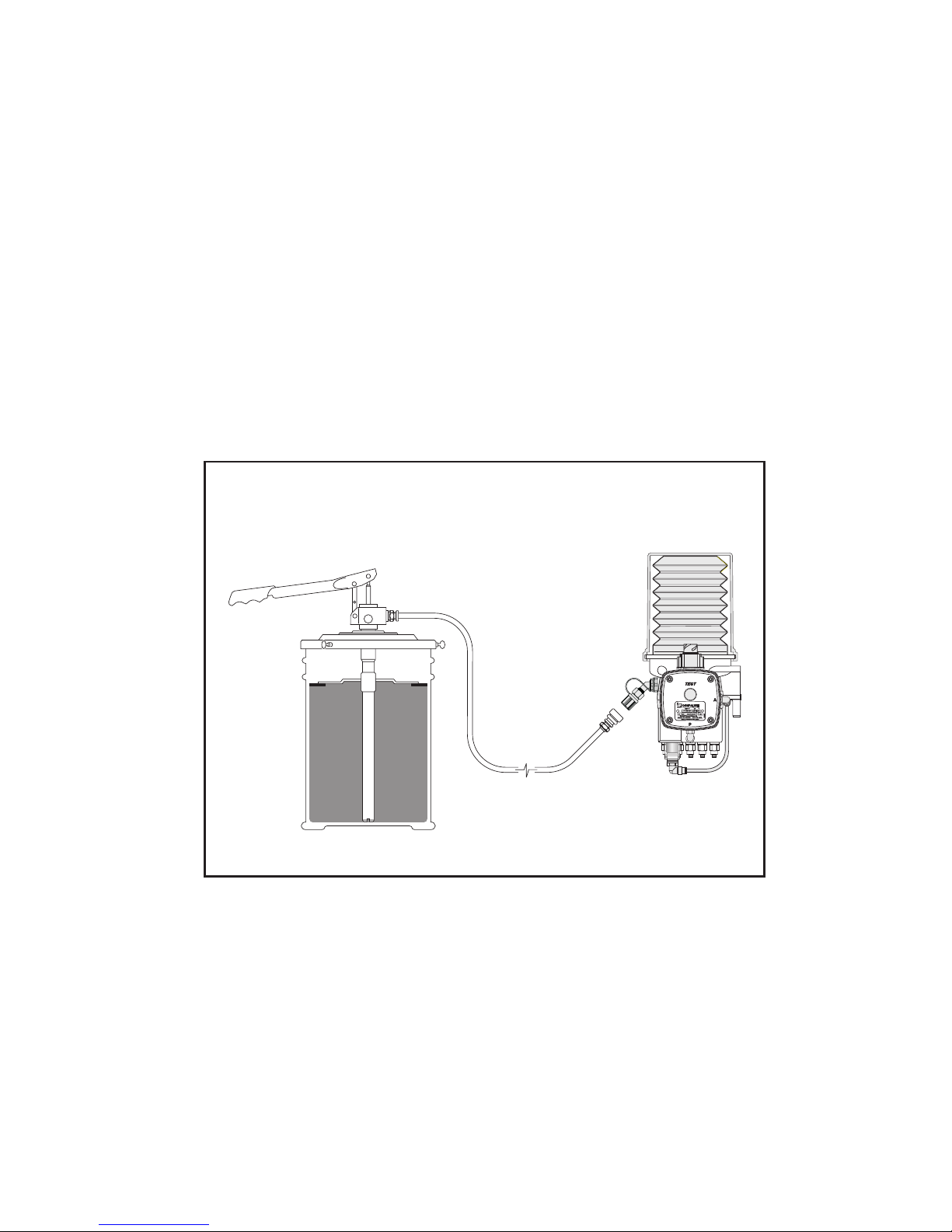
4. Remove the cap from the new grease cartridge, but leave the foil in place.
Screw the cartridge clockwise onto the pump (Figure 4.7). The foil is removed
automatically.
Figure 4.7 Fitting a new grease cartridge
5. Clean the protection cover, place it on the pump (Figure 4.8) and turn it
clockwise.
Figure 4.8 Fitting the protection cover
Gro_G0105_406
Gro_G0105_407
Page 31
CompAlube Automatic greasing system
Operation
31
Publication date: September 2005
EG0105P02
4.4 Refilling through the filling connection
The grease in the reservoir must be refilled as soon as the minimum level is reached.
A filling pump must be used for this. The filling procedure (Figure 4.9) is as follows:
1. With a new filling pump, the filling hose must first be filled with grease. This
prevents air from being pumped into the reservoir. Place the quick coupling
of the filling hose on the quick coupling of the filling pump cover and pump
until the filling hose is filled with grease.
2. Remove the dust cap from the filling connection.
3. Carefully clean the filling connection and the filling hose coupling.
4. Place the filling hose on the filling connection.
5. Fill the reservoir to the maximum level (1 cm below the top of the reservoir).
6. Remove the filling hose from the filling connection and place the filling hose
op the quick coupling of the filling pump.
7. Place the dust cap on the filling connection.
8. There is a filter in the filling connection of the pump. If filling is difficult, the
filter may be dirty. If it is, remove the filter and clean it.
Figure 4.9 Filling with the filling pump
Gro_G0105_408
Page 32

Operation32
Publication date: September 2005
CompAlube Automatic greasing system
EG0105P02
4.5 Setting the greasing interval
4.5.1 CompAlube with brake-counter
The greasing interval is set on the brake-counter integrated in the CompAlube
pump unit. The number of times that the vehicle brakes is used as the basis for the
greasing interval. A gauge is supplied for setting the greasing interval. This gauge
is located on the inside of the brake-counter cover. For further information see:
paragraph 5.10 - Putting into service.
4.5.2 CompAlube with electronic timer
The greasing interval is set on the electronic timer integrated in the pump unit. To
set the greasing interval, you can set the DIP switches under the electronic timer
cover to a different combination. See paragraph 5.10 - Putting into service for
information about the method that you must use to set the greasing interval.
4.6 Venting
During normal operation, the greasing system never needs to be vented. The pump
may only have to be vented if the grease cartridge is allowed to become completely
empty, see paragraph 5.9 - Venting.
Page 33
CompAlube Automatic greasing system
Installation
33
Publication date: September 2005
EG0105P02
5.
5. INSTALLATION
your efficiency is our challenge
Page 34

Installation34
Publication date: September 2005
CompAlube Automatic greasing system
EG0105P02
5.1 Introduction
To install a Groeneveld CompAlube greasing system, the following materials/
components must be fitted and the following tasks carried out:
1. The CompAlube pump, including grease reservoir, control unit, metering
units and grease-pressure indicator.
2. The grease lines from the metering units to the individual grease points.
3. The pneumatic lines between the vehicle's compressed air system and the
pump unit.
4. The electrical cables.
5. Venting the greasing system.
6. Setting and preparing the system for service.
5.2 General installation instructions
1. Before you start installing the greasing system, check whether all grease
points are open and properly greased. If not, grease them. This prevents
damage being caused by a lack of grease.
2. Prevent contamination from entering the greasing system during installation.
Use clean tools and clean the surroundings (vehicle or machine) of the
location of the pump unit before you start installing it. Even minor
contamination can cause the greasing system to malfunction!
3. When fitting the air and grease lines, take care that:
• you do not fit the lines to or near parts that become hot, such as exhaust,
retarder, compressor, turbo or air-conditioning;
• the lines are fitted neatly and straight, and are fitted in place with large
or small tie wraps or clamps;
• the lines are not fitted next to or over moving parts in such a way that
they may become damaged (in time);
• the lines that serve moving parts have sufficient slack to follow the
movements of these parts. Check that!;
• grommets are used wherever there is a chance of a line being damaged.
Page 35

CompAlube Automatic greasing system
Installation
35
Publication date: September 2005
EG0105P02
5.3 Safety precautions
1. Ensure that dangerous situations are avoided when carrying out work
(installation or repair).
2. Always apply or use adequate safety precautions to prevent bodily harm and
damage before you start working.
3. Ensure that a machine or vehicle is immobilised before you start work.
Remove the ignition key and store it in a safe place. Block parts that may
move of their own accord. Engage the parking brake.
4. Pay special attention to blocking tailboards, loading flaps, and drop flaps, etc.
Make sure that these parts are safe to work underneath, and that they cannot
fall.
5. Never work underneath a vehicle or machine that is raised by a jack only.
Always use a jack stand and check that the ground is firm and flat enough.
6. Keep in mind that a vehicle with air suspension may drop of its own accord, as
a result of loss of air pressure.
7. Only work under the cab if it is fully tilted (and latched). Otherwise, a support
must be placed underneath the cab to ensure that it cannot fall back.
8. If necessary, disconnect the ground cable from the vehicle's battery. This
prevents electrical equipment from being inadvertently activated.
9. Avoid working on the cooling system without allowing it to cool down first.
The system is pressurised and the toxic coolant can easily spray outwards and
cause burns.
10. Adhere to all regulations, specifications and limitations, as specified by the
manufacturer of the vehicle or machine.
11. Use only clean tools that are suitable for the task you want to perform with
them.
12. A vehicle or machine may only be operated if the operation is fully known. If
necessary, consult an expert.
13. Keep the working area clean and tidy; this promotes safety.
Page 36

Installation36
Publication date: September 2005
CompAlube Automatic greasing system
EG0105P02
5.4 Installation of the CompAlube pump unit
5.4.1 The CompAlube pump unit
The CompAlube pump unit is always made specifically for the vehicle for which it
is intended. Before the CompAlube pump unit can be installed on the vehicle, the
following must be checked:
1. Does the pump have the right number and type of metering units?
2. Are the right line combinations present and are all lines long enough?
If the pump unit is part of a kit, it is usually correctly assembled and fitted with the
right grease lines. If the pump unit is not part of a kit or if the grease lines are not
assembled, we advise you to first fill the grease lines before fitting the pump unit.
Use only NLGI-0 grease.
5.4.2 Fitting the pump on the vehicle
1. Determine where you want to fit the pump unit. Make sure that:
• the grease lines are long enough, and reach the grease points;
• the pump can be well accessed to replace the cartridge;
• the level in the reservoir can be read;
• the pump is protected against damage.
2. Check first if you can use existing holes in the chassis to fit the fitting bracket.
Only drill new holes when you cannot use the existing holes and check if the
positions where you want to drill are safe. Always follow the vehicle
manufacturer's instructions. Do not let the fitting bracket rest on the chassis
profile flange and do not drill holes in the flange for extra fastening of the
fitting bracket. Before drilling a hole, make sure that you will not damage
some essential component of the vehicle, such as ducts, wiring or air tanks.
After drilling, clear the area of debris with an air gun or brush.
Warning!
If the fitting bracket is to be welded onto the vehicle, the relevant
instructions and regulations issued by the vehicle's manufacturer must be
strictly adhered to.
3. Fit the fitting bracket (with the pump) on the chassis.
4. Remove the blind plugs from the air connections on the pump.
Page 37
CompAlube Automatic greasing system
Installation
37
Publication date: September 2005
EG0105P02
5.5 Grease lines and couplings
The grease lines, which are connected to the metering units on the pump unit at
one end, are connected by special couplings to the grease points at the other end.
These couplings can be supplied in a wide variety of types. Which type should be
used at a grease point depends on:
• the thread in the grease point;
• the position of the grease point;
• the type of grease line used;
• the operating conditions.
Always make sure that the thread of the coupling matches that of the grease point.
Elbow couplings with metric thread are marked with the letter "M". Straight
couplings with metric thread are marked with a groove on the hexagonal of the
coupling.
If a grease plan is available, it will specify which coupling or combination of
couplings must be used at each grease point.
Usually, polyamide grease lines with an outside diameter of 3/16" (4.8 mm) are
used on the CompAlube pump unit. To be able to connect these grease lines easily
and quickly, the metering units on the pump unit are fitted with push-in couplings
as standard. If polyamide grease lines cannot be used for some grease points, the
metering units that serve these grease points must be fitted with pipe (nut and
cutting-ring) couplings.
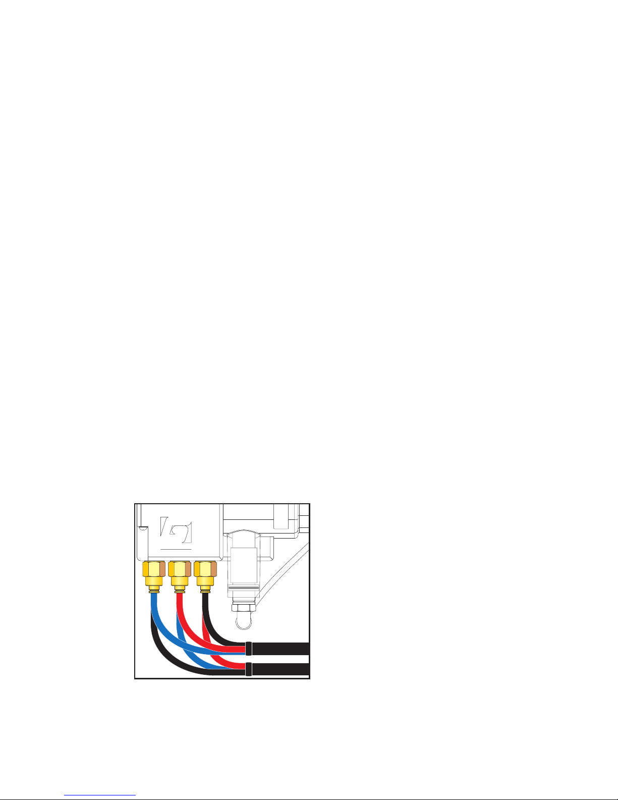
The polyamide lines can be supplied as composite lines (2 or 3 polyamide lines
inside a common plastic outer jacket). To make them clearly distinguishable at both
ends of the jacket, each grease line has a different colour (red, blue or black)
(Figure 5.1). If the different polyamide lines in an outer jacket are connected to
metering units with different outputs, this must be done as follows:
• metering unit with the lowest output : Red line
• metering unit with intermediate output : Blue line
• metering unit with the highest output : Black line
Figure 5.1 Polyamide lines
GROENEVELD
Gro_G0105_500
Page 38
Installation38
Publication date: September 2005
CompAlube Automatic greasing system
EG0105P02
5.5.1 Fitting the grease lines and couplings
Caution!
Do not add or modify existing grease points on your own initiative. Certain
constructions can be weakened by drilling holes. Always follow the relevant
vehicle manufacturer's instructions.
1. First remove the original grease nipple from the grease point and replace it
with the correct coupling or combination of couplings (see the grease plan).
If the grease point to be connected is an "added grease point", a hole must
be drilled (at the location shown on the grease plan). Now, a thread must be
tapped, after which the coupling or combination of couplings can be fitted.
With elbow couplings, make sure that they are at such a angle that the
opening points in the direction of the grease line.
2. Before you start to lay the (composite) grease line, first determine the most
favourable or suitable route.
3. Roughly determine the required length of line and cut or saw the line off.
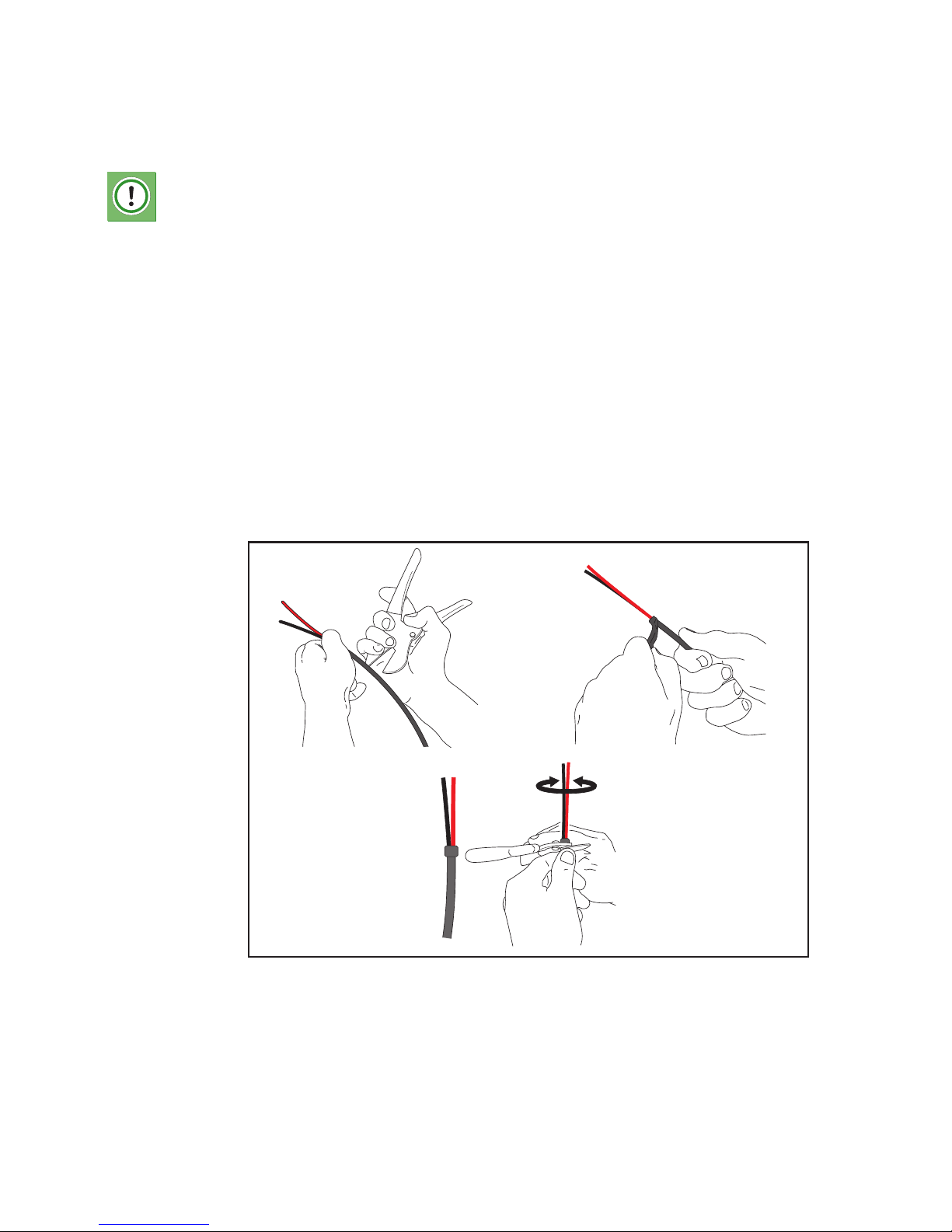
4. With composite lines (polyamide), roughly determine the desired length of
the individual lines and strip the outer jacket along this length (Figure 5.2.A/
B). Make sure that you do not damage the individual lines in the jacket. The
stripped part of the composite grease line must look as in (Figure 5.2.C).
Figure 5.2 Removing the outer jacket
Gro_G0105_501
AB
C
Page 39

CompAlube Automatic greasing system
Installation
39
Publication date: September 2005
EG0105P02
5. Fasten the grease line with clamps or brackets to just before the coupling on
the grease point.
Warning!
If grease lines are laid along booster hoses, brake booster rubbers must
always be used. These rubbers prevent the booster hose from being
damaged or from being pinched by clamps
6. Cut the grease line to the correct length and connect it to the coupling.
7. Fasten any loose part of the grease line to the coupling.
5.5.2 Maximum grease line length
Caution!
The maximum line lengths are determined for use with GreenLube EP-0
grease. If a different type of grease is used, the maximum line lengths can
be different. At temperatures below -10°C/14°F, the ouput from the
metering units can drop by 30%.
Temperature Maximum length
of PA 3/16" line
with metering unit
no. 1
Maximum length
of PA 3/16" line
with metering unit
no. 3
Maximum length
of PA 3/16" line
with metering unit
no. 8
-15°C/5°F 7.5 metres 7.5 metres 7.5 metres
-20°C/-4°F 5 metres 5 metres 5 metres
-25°C/-13°F 3 metres 3 metres 3 metres
Page 40
Installation40
Publication date: September 2005
CompAlube Automatic greasing system
EG0105P02
5.6 Pneumatic lines
Warning!
Before installing the pneumatic lines, you must always check if there are
any specific legal regulations or provisions. Always follow these regulations
or provisions. Failure to do so might have dire consequences in connection
with the legal liability, accidents and damages, etc.
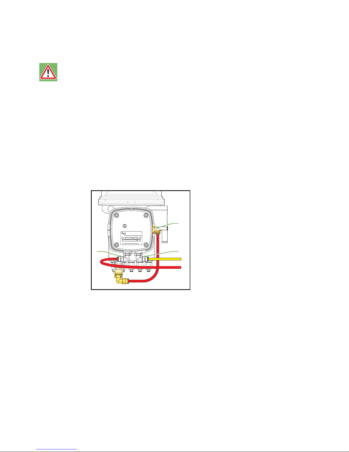
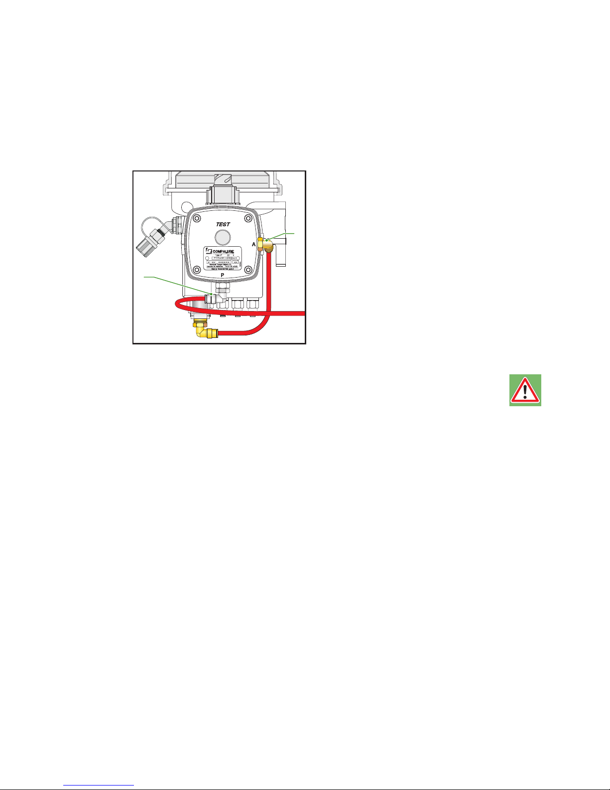
5.6.1 Pneumatic CompAlube with brake-counter
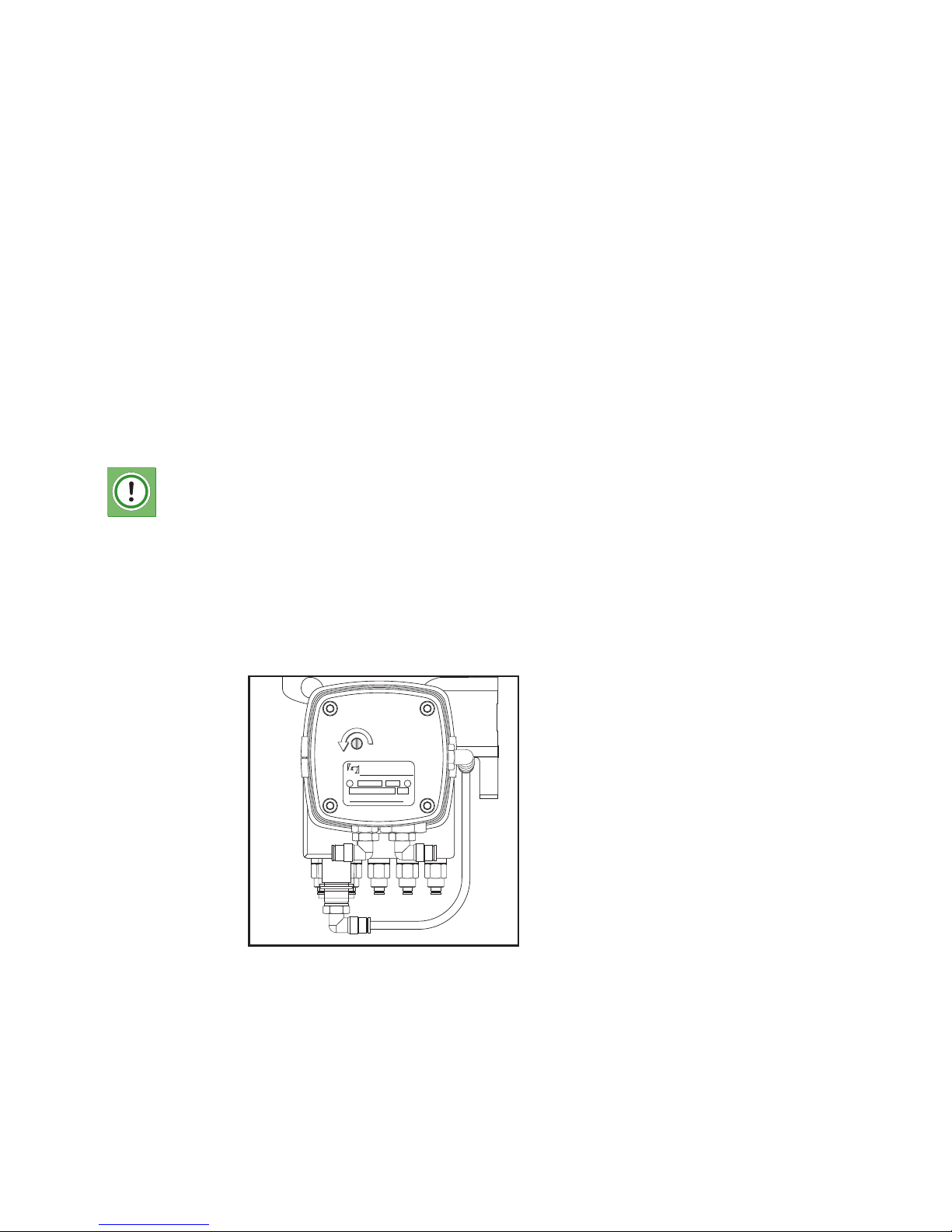
Two air lines must be connected to the pneumatic CompAlube with brake-counter
(Figure 5.3):
• The air supply line - the line between vehicle's the air tank and port 'P'
on the brake-counter. This air line is red.
• When the brake-counter is used, the brake service line is connected to
port 'S' on the brake-counter. Use the yellow line.
Both pneumatic lines are made of high-grade polyamide and have an outer
diameter of 8 mm (5/16").
Figure 5.3 Pneumatic CompAlube with brake-counter
PNEUMATIC PUMP
Type n c.c.
o
Groeneveld Transport Efficiency B.V.
Gorinchem, the Netherlands
Made by Groeneveld Italia s.r.l.(Lc)
S
P
A
Gro_G0105_502
P
S
A
Page 41
CompAlube Automatic greasing system
Installation
41
Publication date: September 2005
EG0105P02
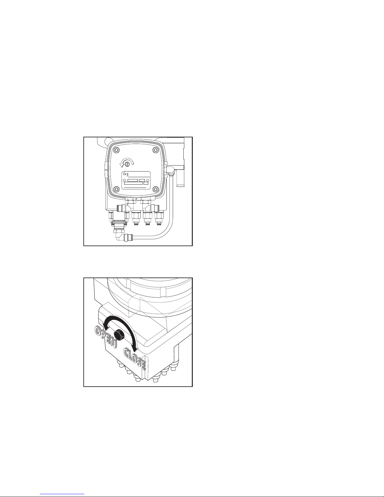
5.6.2 Pneumatic CompAlube with electronic timer
One air line must be connected to the pneumatic CompAlube with electronic timer
(Figure 5.4):
• The air supply line - the line between vehicle's the air tank and port 'P'
on the brake-counter. This air line is red.
Figure 5.4 Pneumatic CompAlube with electronic timer
Warning!
Release the pressure in the air tank(s), before you install the air supply line.
Gro_G0105_503
P
A
Page 42

Installation42
Publication date: September 2005
CompAlube Automatic greasing system
EG0105P02
5.7 Electrical cables
5.7.1 The pneumatic CompAlube with electronic timer
Connect the wires according to the following table.
5.7.2 The electrical CompAlube with electronic timer
Connect the wires according to the following table.
5.8 CompAlube for lorries
5.8.1 Pneumatic CompAlube with integrated brake-counter
A magnetic valve set is required if you want to install the pneumatic CompAlube
with integrated brake-counter on a lorry. On lorries, it is not allowed to connect
the integrated brake-counter directly to the pneumatic braking system and this is
avoided by the use of the magnetic valve set.
This system corresponds with the standard CompAlube system, only the command
pulse now comes from the brake light switch.
A 2-wire cable, connected to a cable coming from the brake light switch and the
ground, is connected to the terminals on the magnetic valve. The magnetic valve
should be connected in parallel with the brake lights, so that the magnetic valve
opens at each brake pulse and air flows from the accessoires air tank to the
command piston (S) of the brake-counter.
Pin no. Wire colour Wire diameter Description
1 Red 2.5 mm² +15 pump connection
2 Black 2.5 mm² -31 pump connection
Pin no. Wire colour Wire diameter Description
1 Red 2.5 mm² +15 pump connection
2 Black 2.5 mm² -31 pump connection
3 Grey 0.75 mm² + control lamp connection
4 White 0.75 mm² - control lamp connection
Page 43
CompAlube Automatic greasing system
Installation
43
Publication date: September 2005
EG0105P02
5.9 Venting
5.9.1 The pneumatic CompAlube with brake-counter
Normally, the pump never needs to be vented because it is vented and tested
before delivery.
However, if the grease cartridge has been completely empty, the pump may need
to be vented again:
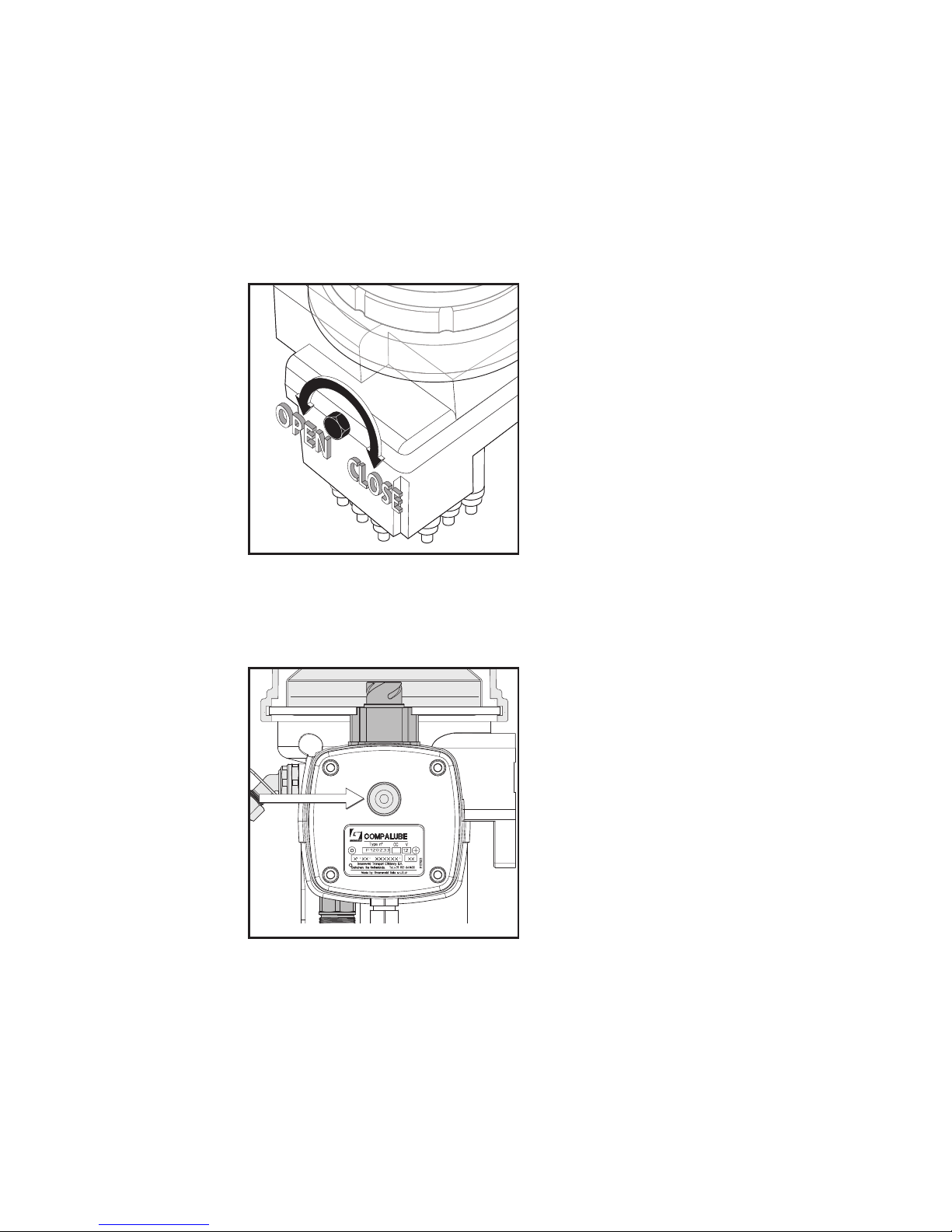
1. Push the test screw inward and slowly turn it anti-clockwise, until a greasing
cycle (if running) is finished (air will now escape from the pump). (Figure 5.5)
Figure 5.5 Test screw
2. Open the venting screw (Figure 5.6).
Figure 5.6 Venting screw
3. Turn the test screw slowly anti-clockwise until a greasing cycle is started (air
will flow into the pump).
4. Close the venting screw (Figure 5.6).
5. Repeat this procedure until only grease (and no more air) exits the vent
opening.
PNEUMATIC PUMP
Type n c.c.
o
Groeneveld Transport Efficiency B.V.
Gorinchem, the Netherlands
Made by Groeneveld Italia s.r.l.(Lc)
Gro_G0105_504
Gro_G0105_505
Page 44
Installation44
Publication date: September 2005
CompAlube Automatic greasing system
EG0105P02
5.9.2 The CompAlube with electronic timer
Normally, the pump never needs to be vented because the pump is vented and
tested before delivery.
However, if the grease cartridge has been completely empty, the pump may need
to be vented again:
1. Open the venting screw (Figure 5.6).
Figure 5.7 Venting screw
2. Press the test button on the right-hand side of the pump unit for a minimum
of three seconds but not longer than five seconds, until you hear that the
pump motor is switched on (Figure 5.8).
Figure 5.8 Test button
3. Close the venting screw (Figure 5.6) as soon as only grease exits the vent
opening.
5.9.3 Grease lines
If prefilled grease lines were not used during the system installation, greasing
cycles must be performed (see steps 1 and 3 in paragraph 5.9.1 or step 2 in
paragraph 5.9.2) until grease exits the ends of the lines.
Gro_G0105_506
Gro_G0105_507
Page 45
CompAlube Automatic greasing system
Installation
45
Publication date: September 2005
EG0105P02
5.10 Putting into service
After the installation, the CompAlube greasing system must be put into service.
5.10.1 The pneumatic CompAlube with brake-counter
The main task is to set the brake-counter. The number of brake demands (the
greasing interval) that must be set depends on several factors:
• the grease demand of the grease points.
• the operating conditions (highway, city traffic, building site, etc.).
A gauge supplied with the brake-counter is used to set the number of brake
demands to beween 10 and 80 brake demands.
The setting procedure:
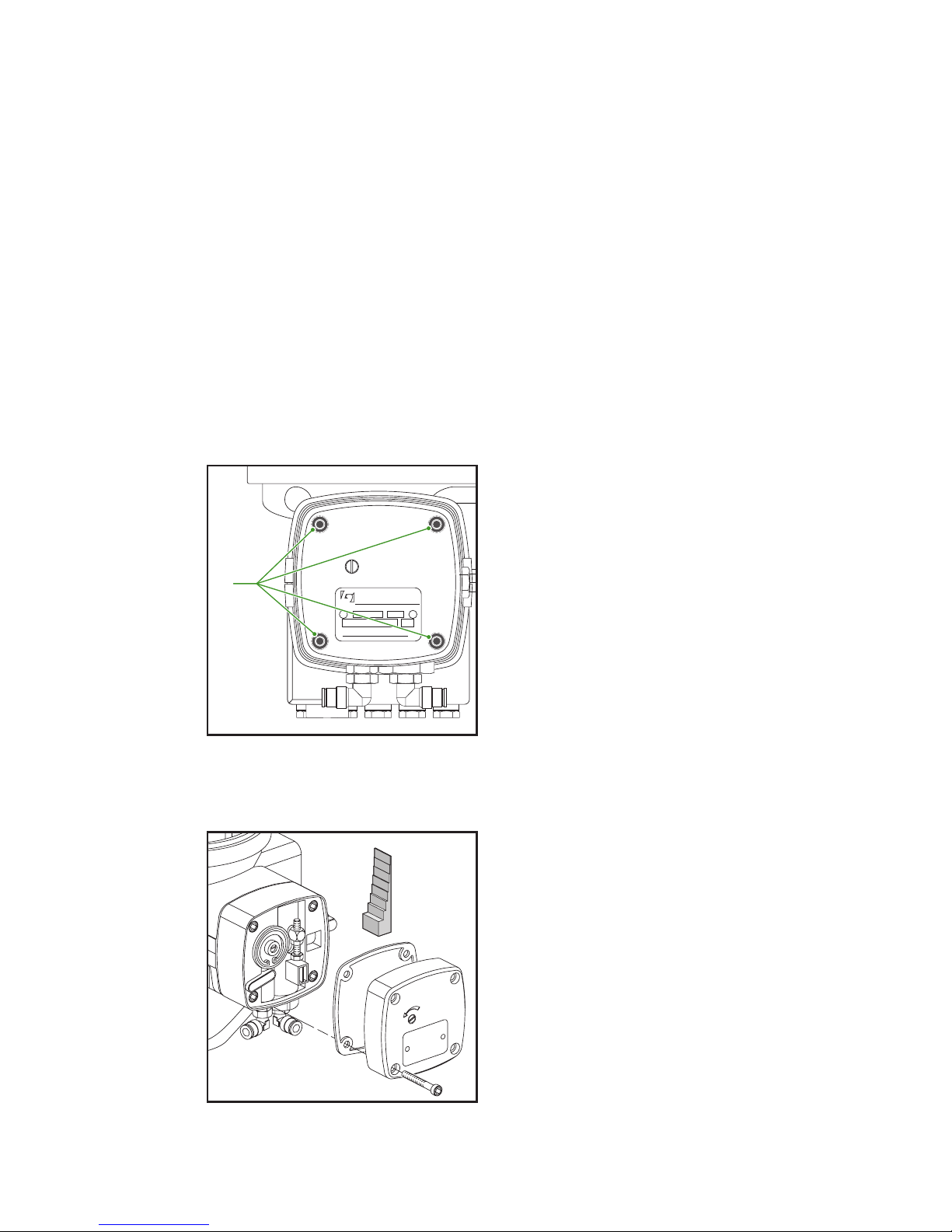
1. Remove the 4 screws from the cover of the brake-counter with a suitable
Allen key (Figure 5.9).
Figure 5.9 Fastening screws
2. Remove the cover (remember the gasket) and take the gauge out of the cover
(Figure 5.10).
Figure 5.10 Gauge
PNEUMATIC PUMP
Type n c.c.
o
Groeneveld Transport Efficiency B.V.
Gorinchem, the Netherlands
Made by Groeneveld Italia s.r.l.(Lc)
Gro_G0105_508
A
Gro_G0105_509
Page 46
Installation46
Publication date: September 2005
CompAlube Automatic greasing system
EG0105P02
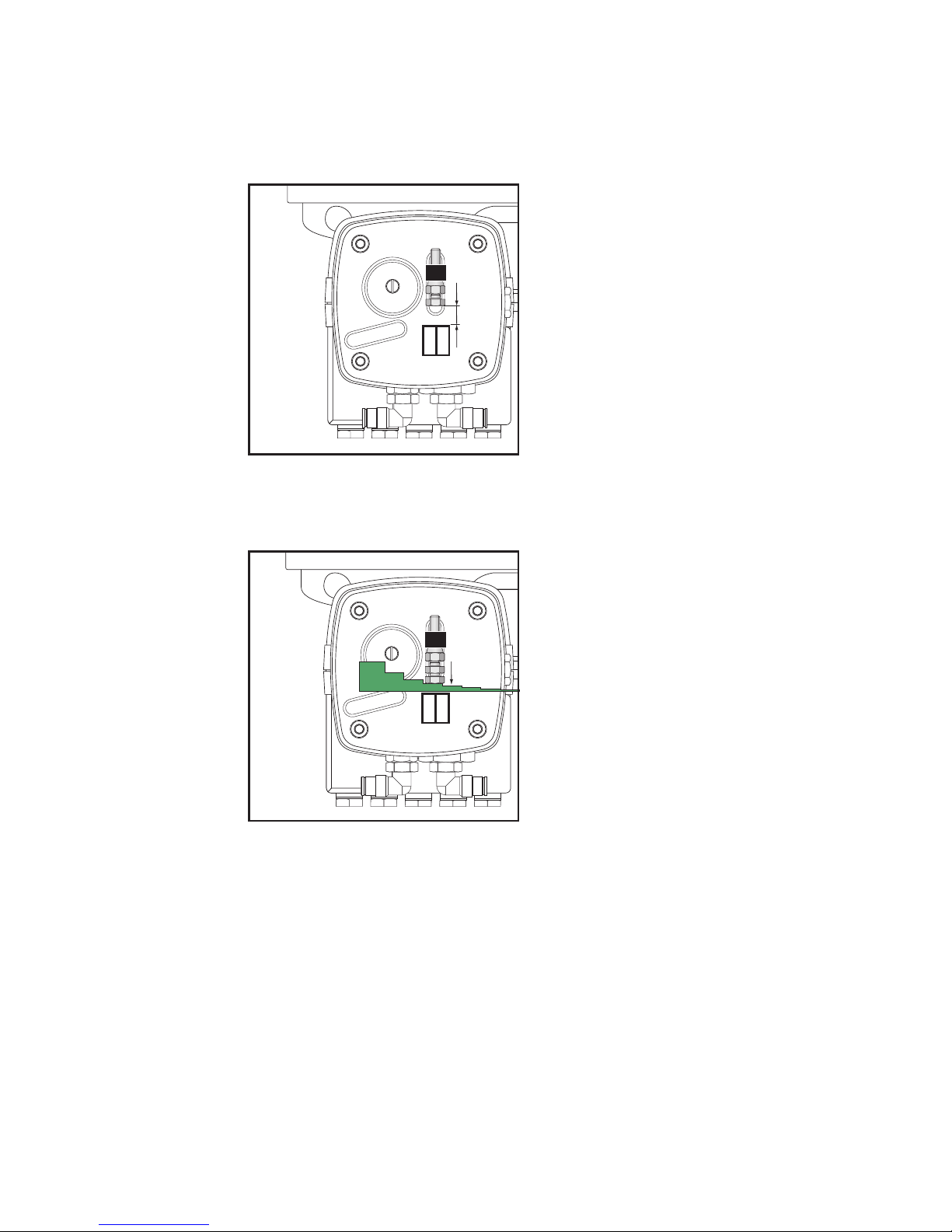
3. Make sure that the setting screw attached to the piston in the brake-counter
does not rest on the end stop by activating the vehicle's brakes (Figure 5.11).
Figure 5.11 Setting screw
4. Use the gauge and two open-ended spanners (10 mm) to set the desired
number of brake commands (Figure 5.12).
Figure 5.12 Setting the desired number of brake commands
5. Replace the cover. Check that the gasket is positioned properly. Fit the cover
with the 4 screws (Figure 5.9).
Gro_G0105_510
Gro_G0105_511
Page 47
CompAlube Automatic greasing system
Installation
47
Publication date: September 2005
EG0105P02
5.10.2 The pneumatic CompAlube with electronic timer
The main task is to set the electronic timer. The duration of the greasing interval
depends on:
• the grease demand of the grease points.
• the operating conditions (highway, city traffic, building site, etc.).
The setting procedure:
1. Remove the 4 screws from the cover of the timer with a suitable Allen key
(Figure 5.9).
2. Remove the cover (remember the gasket).
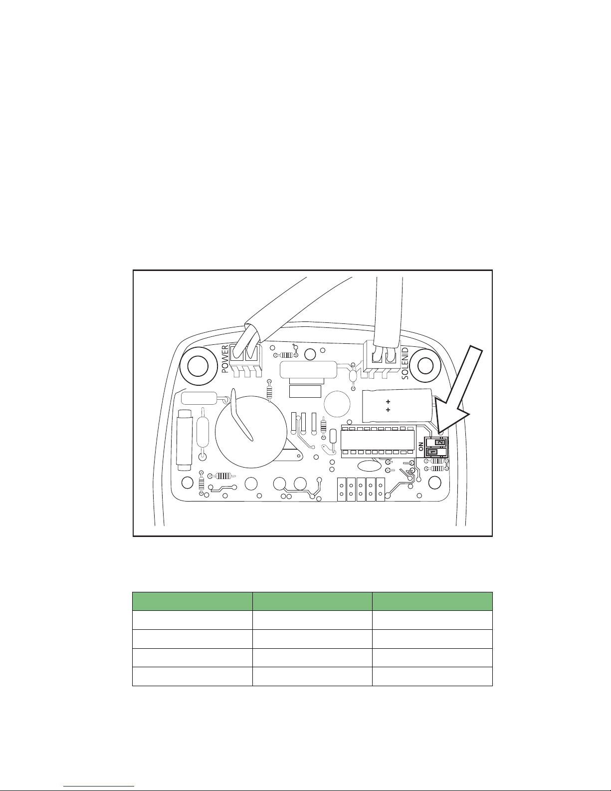
3. There are two DIP switches on the printed circuit board (Figure 5.13). Set the
switches to the right position for the desired greasing interval (see following
table).
Figure 5.13 DIP switches
DIP switch settings
4. Replace the cover. Check that the gasket is positioned properly. Fit the cover
with the 4 screws.
Interval DIP switch 1 DIP switch 2
90 minutes ON ON
120 minutes ON OFF
150 minutes OFF ON
180 minutes OFF OFF
Gro_G0105_512
Page 48
Installation48
Publication date: September 2005
CompAlube Automatic greasing system
EG0105P02
5.10.3 The electrical CompAlube with electronic timer
The main task is to set the electronic timer. The duration of the greasing interval
depends on:
• the grease demand of the grease points.
• the operating conditions (highway, city traffic, building site, etc.).
The setting procedure:
1. Remove the 4 screws from the cover of the timer with a suitable Allen key
(Figure 5.9).
2. Remove the cover (remember the gasket).
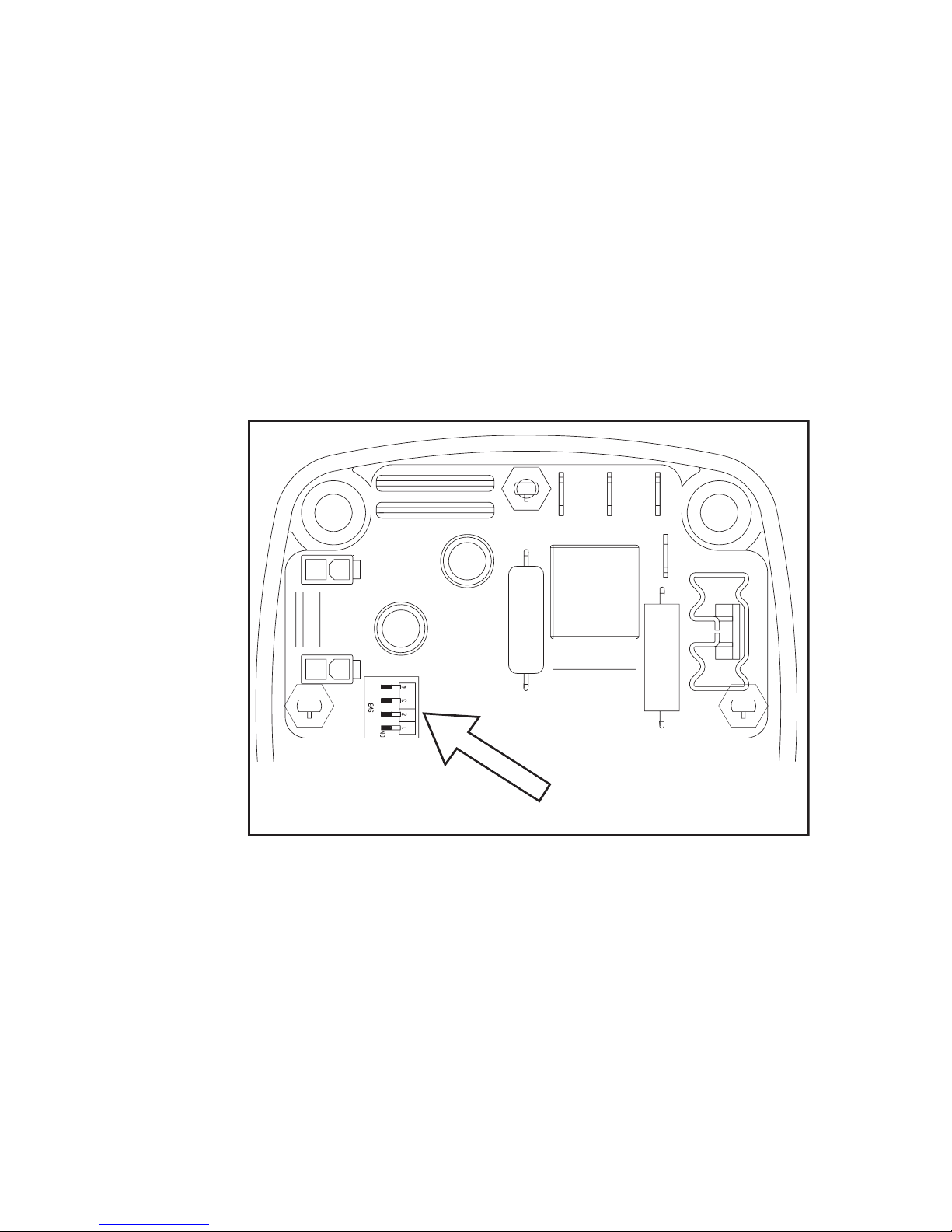
3. There are 4 DIP switches on the printed circuit board (Figure 5.13). Set the
switches to the right position for the desired greasing interval (see following
table).
Figure 5.14 DIP switches
Gro_G0105_513
Page 49

CompAlube Automatic greasing system
Installation
49
Publication date: September 2005
EG0105P02
DIP switch settings
4. Replace the cover. Check that the gasket is positioned properly. Fit the cover
with the 4 screws.
Interval DIP
switch 1
DIP
switch 2
DIP
switch 3
DIP
switch 4
30 minutes OFF OFF OFF not relevant
45 minutes ON OFF OFF not relevant
60 minutes OFF ON OFF not relevant
90 minutes ON ON OFF not relevant
120 minutes OFF OFF ON not relevant
150 minutes ON OFF ON not relevant
180 minutes OFF ON ON not relevant
240 minutes ON ON ON not relevant
Page 50

Installation50
Publication date: September 2005
CompAlube Automatic greasing system
EG0105P02
Notes
Page 51
CompAlube Automatic greasing system
Maintenance
51
Publication date: September 2005
EG0105P02
6.
6. MAINTENANCE
your efficiency is our challenge
Page 52

Maintenance52
Publication date: September 2005
CompAlube Automatic greasing system
EG0105P02
6.1 Introduction
The maintenance of the Groeneveld CompAlube greasing system can be combined
with the normal maintenance on the vehicle or the machine.
Caution!
The automatic greasing system significantly reduces the time and effort
spent on manual greasing. However, do not forget that universal joints, for
instance, must still be greased by hand.
6.2 Periodic check
1. Check the grease-pressure indicator (must be green) or the control lamp
(must not be lit).
2. Check the grease level in the grease cartridge (replace the cartridge time or
refill the cartridge through the filling connection).
3. Check the pump unit for damage and leakage.
4. Check the grease lines for damage and leakage.
5. Check the condition of the grease points on the vehicle. There must be
sufficient fresh grease present.
6. Perform a test cycle to check the system operation. Note that every time you
perform a test cycle a small amount of grease is supplied to the grease points
(do not perform a test cycle too often).
Warning!
If you use a high-pressure air or water gun to clean the vehicle, do not spray
directly onto the greasing system pump unit. Water oo dirt might enter the
pump unit through the vent openings.
Page 53

CompAlube Automatic greasing system
Maintenance
53
Publication date: September 2005
EG0105P02
6.3 Trouble shooting
6.3.1 Pneumatic CompAlube malfunctions
Problem Cause Solution
Grease-pressure indicator
shows 'red'.
1. Cartridge or reservoir is
empty.
Replace cartridge with full
cartridge or refill the
reservoir through the
filling connection
2. Internal leakage in a
metering unit.
Check if a grease point is
receiving too much grease.
Replace the metering unit
that serves this grease
point.
3. Defective greasepressure indicator.
Repair or replace the
grease-pressure indicator.
4. Air in the system. Vent the system.
5. Defective pump. Repair or replace the
pump.
All grease points are too
dry, while the system
appears to operate
properly (the greasepressure indicator shows
'green').
1. Brake-counter not set
properly (number of set
brake applications
between greasing cycles
is too large).
Set brake-counter correctly.
2. The grease used is not
suitable for the current
working environment
(temperature too low).
Replace the cartridge with
a cartridge containing the
correct grease.
3. The pump is not
receiving any
compressed air from the
air tank.
Check the air supply and
pressure in the air tank.
Check the air line beween
air tank and pump.
4. The pump is not
receiving any signals
through the brakecommand air line.
Check the air line beween
pump and valve. Check the
restriction in the coupling
on the fast-braking valve
for contamination.
All grease points are too
greasy
Brake-counter not set
properly (number of set
brake applications between
greasing cycles is too small).
Set brake-counter correctly.
Some grease points are dry,
while others receive
sufficient grease.
1. Grease line(s) damaged. Repair or replace grease
line(s).
2. Metering unit(s)
defective.
Replace the metering
unit(s).
A single grease point is
receiving too much grease.
Metering unit leaks
internally.
Replace the metering unit.
Page 54

Maintenance54
Publication date: September 2005
CompAlube Automatic greasing system
EG0105P02
6.3.2 Electrical CompAlube malfunctions
Problem Cause Solution
The control lamp is lit
continuously.
1. Cartridge or reservoir is
empty.
Replace cartridge with full
cartridge or refill the
reservoir through the
filling connection
2. Internal leakage in a
metering unit.
Check if a grease point is
receiving too much grease.
Replace the metering unit
that serves this grease
point.
3. Defective greasepressure switch.
Repair or replace the
grease-pressure switch.
4. Air in the system. Vent the system.
5. Defective pump. Repair or replace the
pump.
All grease points are too
dry, while the control lamp
does not indicate a defect.
1. Time switch not set
properly (set interval
between greasing cycles
is too large).
Set time switch correctly.
2. The grease used is not
suitable for the current
working environment
(temperature too low).
Replace the cartridge with
a cartridge containing the
correct grease.
3. No voltage. Check the wiring and the
fuse.
All grease points are too
greasy
Time switch not set
properly (set interval
between greasing cycles is
too small).
Set time switch correctly.
Some grease points are dry,
while others receive
sufficient grease.
1. Grease line(s) damaged. Repair or replace grease
line(s).
2. Metering unit(s)
defective.
Replace the metering
unit(s).
A single grease point is
receiving too much grease.
Metering unit leaks
internally.
Replace the metering
unit(s).
Page 55
CompAlube Automatic greasing system
Technical specifications
55
Publication date: September 2005
EG0105P02
7.
7. TECHNICAL SPECIFICATIONS
your efficiency is our challenge
Page 56

Technical specifications56
Publication date: September 2005
CompAlube Automatic greasing system
EG0105P02
7.1 Pump
Description Pneumatic pump
with brake-counter
Pneumatic pump
with electronic
timer
Electrical pump
with electronic
timer
Power supply
voltage
n.a. 12 VDC or 24 VDC 12 VDC or 24 VDC
Current
consumption
(nominal at 20°C)
n.a.
1A (12 VDC)
0.5A (24 VDC)
9A (12 VDC)
4A (24 VDC)
Required air
pressure
6 - 10 bar 6 - 10 bar n.a.
Pressure ratio 9 : 1 9 : 1 n.a.
Grease output 20 cm³ per stroke 20 cm³ per stroke n.a.
Grease pressure 54 - 90 bar 54 - 90 bar 55 bar
Maximum
allowable grease
pressure
100 bar (1400 psi) 100 bar (1400 psi) 100 bar (1400 psi)
Temperature range
-25°C to +80°C
(-13°F to +160°F)
-25°C to +80°C
(-13°F to +160°F)
-25°C to +80°C
(-13°F to +160°F)
Contents of grease
cartridge
1.8 litres 1.8 litres 1.8 litres
Type of grease NLGI EP-0 grease NLGI EP-0 grease NLGI EP-0 grease
Weight of complete
pump
7 kg 7 kg 7 kg
Weight of grease
cartridge
2 kg 2 kg 2 kg
Connector type n.a. bayonet bayonet
Type of approval in
accordance with the
following
guidelines
Protection class IP67 (pump unit) IP67 (pump unit) IP67 (pump unit)
Page 57
CompAlube Automatic greasing system
Technical specifications
57
Publication date: September 2005
EG0105P02
7.2 Metering units
Maximum 19 metering units on the CompAlube pump.
7.3 Maximum grease line length
7.4 Brake-counter (pneumatic CompAlube)
7.5 Electronic timer (pneumatic CompAlube)
7.6 Electronic timer (electrical CompAlube)
7.7 Control lamp
Available metering units Output
Type 0 0.025 cm³/greasing cycle
Type 1 0.050 cm³/greasing cycle
Type 2 0.100 cm³/greasing cycle
Type 3 0.150 cm³/greasing cycle
Type 4 0.200 cm³/greasing cycle
Type 8 0.400 cm³/greasing cycle
Type 9 1.000 cm³/greasing cycle
Temperature Maximum length
of PA 3/16" line
with metering unit
no. 1
Maximum length
of PA 3/16" line
with metering unit
no. 3
Maximum length
of PA 3/16" line
with metering unit
no. 8
-15°C/5°F 7.5 metres 7.5 metres 7.5 metres
-20°C/-4°F 5 metres 5 metres 5 metres
-25°C/-13°F 3 metres 3 metres 3 metres
Greasing interval : 10 ... 80 brake applications (adjustable)
Length of greasing cycle
: 3 ... 25 brake applications
(not adjustable: depends on the set greasing
interval)
Greasing interval : 90 ... 180 minutes (adjustable)
Length of greasing cycle : 3 minutes
Greasing interval : 30 ... 240 minutes (adjustable)
Length of greasing cycle : 2 minutes
Power consumption : 3 W
Page 58
Technical specifications58
Publication date: September 2005
CompAlube Automatic greasing system
EG0105P02
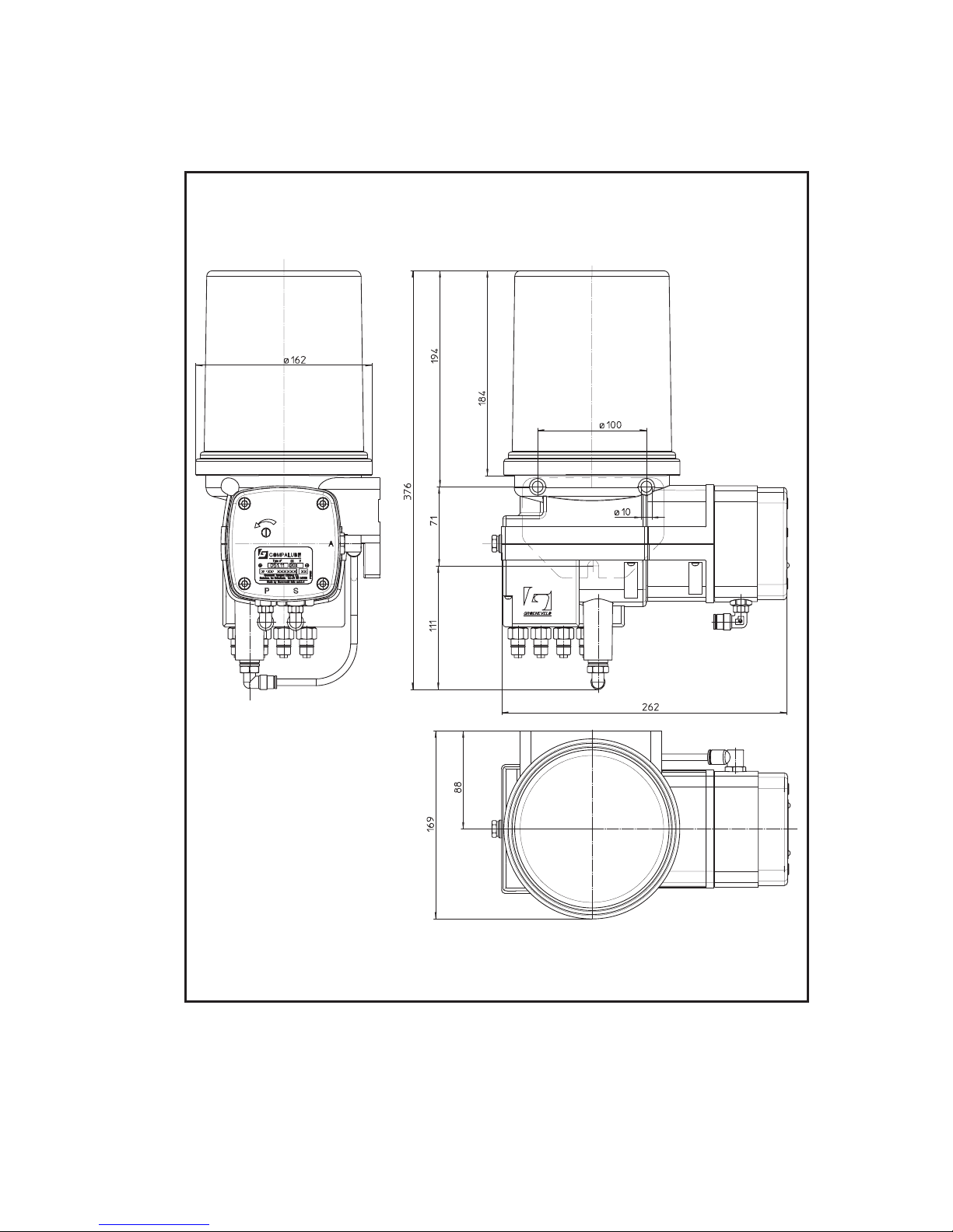
7.8 Pump dimensions
Figure 7.1 Dimensions of the CompAlube pump unit
Gro_G0105_700
Page 59

Groeneveld Australia Pty. Ltd.
18 - 20 Mc Dougall Road
P.O.Box 787
Sunbury, Vic 3429, AUSTRALIA
Tel.: +61 397 4099943
Fax: +61 397 4099665
Groeneveld Belgium NV/SA
Industriezone Hogenakkerhoek
Heirbaan 3, B-9150 Kruibeke, BELGIUM
Tel.: +32 3 8979860
Fax: +32 3 8979861
Groeneveld CPL Systems Canada Inc.
7065 Twiss Road R.R.#3.
LOP 1BO Campbellville, Ontario, CANADA
Tel: + 1 905 875 1017
Fax: + 1 905 875 2125
Groeneveld Deutschland GMBH
Bullermanshof 2B
47441 Moers-Hülsdonk, DEUTSCHLAND
Tel.: +49 2841 793520
Fax: +49 2841 7935222
Groeneveld France
53, rue Antoine Condorcet
38090 Vaulx Milieu, FRANCE
Tel.: +33 4 74999333
Fax: +33 4 74999350
Groeneveld France IT
53, rue Antoine Condorcet
38090 Vaulx Milieu, FRANCE
Tel.: +33 4 74999333
Fax: +33 4 74999350
GINTEC
Active Safety Ltd.,
49, Hasharoshet 1st
Karmiel, 20101, ISRAËL
Tel.: +972 4 9882220
Fax: +972 4 9883179
Groeneveld L’Efficienza nel Trasporto
S.r.l. (GENT)
Via Chiari 100
23868 Valmadrera (Lecco), ITALIA
Tel.: +39 3 41200536
Fax: +39 3 41201539
Groeneveld Italia (GRIT)
Via Chiari 100
23868 Valmadrera (Lecco), ITALIA
Tel.: +39 3 41201133
Fax: +39 3 41201158
Groeneveld Transport Efficiency B.V.
Postbus 777, 4200 AT Gorinchem
THE NETHERLANDS
Tel.: +31 183 641400
Fax: +31 183 624993
Groeneveld Information Technology B.V.
Stephensonweg 12, 4207 HB Gorinchem
THE NETHERLANDS
Tel.: +31 183 641400
Fax: +31 183 641690
Groeneveld New Zealand Ltd.
58 Newton Road
P.O.Box 4509
Mt Maunganui, NEW ZEALAND
Tel.: +64 7 5720684
Fax: +64 7 5724587
Groeneveld Polska Sp. Z.o.o.
Ul. Ostrowska 476
61 - 342 Poznan, POLAND
Tel.: +48 61 8726207/08/09
Fax: +48 61 8798166
Groeneveld South Africa
Unit 65, Sunny Rock Park
Sun Rock Close, Germiston
1401 SOUTH AFRICA
Tel.: +27 11 4503977
Fax.: +27 11 4503980
Groeneveld Ibérica S.A.
Pol. Ind. Mercederias,
C/. Font de Sant Llorenç 36
08720 Vilafranca del Penedès (Barcelona), SPAIN
Tel.: +34 93 8171822
Fax: +34 93 8172061
Groeneveld Transport Efficiency U.K. Ltd.
The Greentec Centre
Gelders Hall Road, Shepshed
Loughborough, Leicestershire, LE12 9NH
UNITED KINGDOM
Tel.: +44 1509 600033
Fax: +44 1509 602000
Groeneveld Transport Efficiency, Inc.
1130 Industrial Parkway North
Brunswick, Ohio 44212, U.S.A.
Tel.: +1 330 2254949
Toll free: +1 800 5867283
Fax: +1 330 2255213
Mobile: +1 800 5867283
Groeneveld Pacific West L.L.C.
1089 Valentine Avenue SE
Pacific, WA 98047, U.S.A.
Tel.: +1 253 8633700
Fax: +1 253 8633131
Mobile: +1 253 6061838
Groeneveld Atlantic South, Inc.
7820 Professional Place, suite #6
Tampa, FL 333637, U.S.A.
Tel.: +1 883 983 1883
Fax: +1 813 983 1873
Toll free: +1 877 977 7772
Page 60

Groeneveld Transport Efficiency B.V., Stephensonweg 12, 4207 HB Gorinchem, Postbus 777, 4200 AT Gorinchem,
the Netherlands. Tel. +31 183 64 14 00, Fax +31 183 62 34 05, http:// www.groeneveld-groep.com
 Loading...