

Page 1
OPERATOR MANUAL
IMPORTANT INFORMATION, KEEP FOR OPERATOR
This manual provides information for:
MODEL WJ100-CC
WATERJET 100
™
CAPKOLD COOKCHILL SYSTEMS
TANK
THIS MANUAL MUST BE RETAINED FOR FUTURE REFERENCE.
READ, UNDERSTAND AND FOLLOW THE INSTRUCTIONS AND
WARNINGS CONTAINED IN THIS MANUAL.
NOTIFY CARRIER OF DAMAGE AT ONCE
It is the responsibility of the consignee to inspect the container upon receipt
of same and to determine the possibility of any damage, including concealed
damage. Unied Brands suggests that if you are suspicious of damage to make
a notation on the delivery receipt. It will be the responsibility of the consignee to
le a claim with the carrier. We recommend that you do so at once.
Manufacture Service/Questions 888-994-7636.
Information contained in this document is known to be current and accurate at the time
of printing/creation. Unified Brands recommends referencing our product line websites,
unifiedbrands.net, for the most updated product information and specifications.
PART NUMBER 172043 REV. A (10/14)
1055 Mendell Davis Drive
Jackson, MS 39272
888-994-7636, fax 888-864-7636
unifiedbrands.net
Page 2

IMPORTANT - READ FIRST - IMPORTANT
CAUTION: BE SURE OPERATORS READ, UNDERSTAND AND FOLLOW THE OPERATING INSTRUCTIONS, CAUTIONS,
AND SAFETY INSTRUCTIONS IN THIS MANUAL.
WARNING: THIS UNIT IS INTENDED FOR USE IN THE COMMERCIAL HEATING, COOKING AND CHILLING OF WATER
AND FOOD PRODUCTS, PER THE INSTRUCTIONS CONTAINED IN THIS MANUAL. OTHER USE COULD
RESULT IN PERSONAL INJURY OR DAMAGE TO EQUIPMENT AND WILL VOID WARRANTY.
WARNING: ELECTRICALLY GROUND THE UNIT AT THE TERMINAL PROVIDED.
WARNING: THE WATERJET MUST BE INSTALLED BY PERSONNEL WHO ARE CERTIFIED REFRIGERATION
TECHNICIANS, AND WELL-QUALIFIED TO WORK WITH ELECTRICITY AND PLUMBING. IMPROPER
INSTALLATION COULD RESULT IN PERSONAL INJURY OR EQUIPMENT DAMAGE.
WARNING: DO NOT HEAT EMPTY UNIT.
WARNING: AVOID ANY EXPOSURE TO THE STEAM ESCAPING FROM THE COVER. DIRECT CONTACT COULD
RESULT IN SEVERE BURNS
WARNING: AVOID ALL DIRECT CONTACT WITH HOT EQUIPMENT SURFACES. DIRECT SKIN CONTACT COULD
RESULT IN SEVERE BURNS.
WARNING: AVOID ALL DIRECT CONTACT WITH HOT FOOD OR WATER IN THE WATERJET. DIRECT CONTACT COULD
RESULT IN SEVERE BURNS.
WARNING: USE OF ANY REPLACEMENT PARTS OTHER THAN THOSE SUPPLIED BY GROEN OR ITS AUTHORIZED
DISTRIBUTORS VOIDS ALL WARRANTIES AND MAY CAUSE BODILY INJURY OR EQUIPMENT DAMAGE.
SERVICE PERFORMED BY OTHER THAN FACTORY AUTHORIZED PERSONNEL WILL VOID ALL
WARRANTIES.
WARNING: TURN OFF ELECTRIC POWER BEFORE WORKING ON INTERNAL COMPONENTS.
WARNING: BEFORE ANY CLEANING OPERATION, TURN THE THERMOSTAT TO “OFF” AND CUT OFF POWER TO
REFRIGERATION AND HEATING ELEMENTS. BEFORE CLEANING ANY PART OTHER THAN THE INSIDE
OF THE UNIT, DISCONNECT THE ELECTRICAL SUPPLY AT THE CIRCUIT BREAKER OR FUSE BOX.
WARNING: BE CAREFUL TO AVOID CONTACT WITH CLEANING PRODUCTS IN ACCORDANCE WITH SUPPLIER
AND MANUFACTURER RECOMMENDATIONS. MANY CLEANERS ARE HARMFUL TO THE SKIN, EYES,
MUCOUS MEMBRANES AND CLOTHING. READ THE WARNINGS AND FOLLOW DIRECTIONS ON THE
CLEANER LABEL.
CAUTION: NEVER LEAVE A CHLORINE SANITIZER IN CONTACT WITH STAINLESS STEEL FOR LONGER THAN 30
MINUTES. LONGER CONTACT CAN CAUSE CORROSION.
WARNING: DO NOT USE ANY FUSE WITH A HIGHER AMP RATING THAN THE RATING SPECIFIED FOR THAT CIRCUIT.
2 OM-WJ100-CC
Page 3

Table of Contents
Important Operator Warnings ............................................................................ page 2
Equipment Description ...................................................................................... page 4
Installation ....................................................................................................... page 5
Initial Start-Up ................................................................................................... page 7
Operation ........................................................................................................ page 8
Maintenance ................................................................................................... page 16
Troubleshooting ............................................................................................... page 17
Parts List ........................................................................................................ page 19
Wiring Schematic ............................................................................................ page 22
Service Log .................................................................................................... page 23
References
ECONOMICS LABORATORY, INC.
St. Paul, Minnesota 55102
NEC1999
NATIONAL FIRE PROTECTION ASSOCIATION
60 Battery March Park
Quincy, Massachusetts 02269
NATIONAL SANITATION FOUNDATION
3475 Plymouth Rd.
Ann Arbor, Michigan 48106
UNDERWRITERS LABORATORIES, INC.
333 Pfingsten Rd.
Northbrook, Illinois 60062
ZEP MANUFACTURING
1390 Lunt Avenue
Elk Grove Village, Illinois 60007
Refrigeration Service Engineers Society
1666 Rand Road
Des Plaines, IL 60016-3552
OM-WJ100-CC 3
Page 4
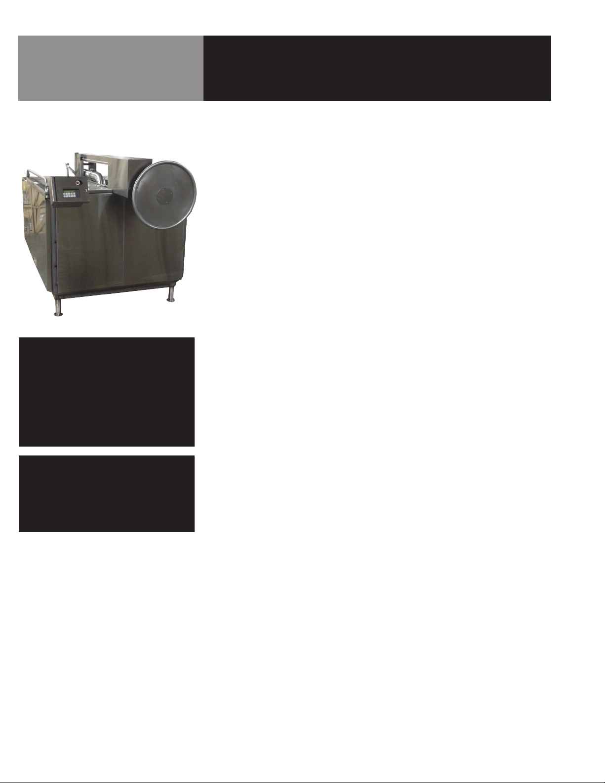
Equipment Description
GROEN MODEL
WJ100 Tank
NOTE
THE GROEN EQUIPMENT YOU HAVE PURCHASED
HAS BEEN CONSTRUCTED FROM QUALITY
MATERIALS AND HAS BEEN CAREFULLY
INSPECTED AND TESTED TO ENSURE THAT
YOU RECEIVE THE BEST POSSIBLE PRODUCT.
WITH REASONABLE CARE AND PERIODIC
MAINTENANCE, YOUR GROEN UNIT SHOULD
PROVIDE YEARS OF PRODUCTIVE SERVICE.
NOTE
PLEASE READ THIS MANUAL CAREFULLY
BEFORE YOU INSTALL OR OPERATE
YOUR EQUIPMENT. It contains information
you will need to install, operate, and
maintain the equipment properly.
The Groen WaterJet™ Model WJ100 is designed to rapidly chill pumpable food products
and ingredients packaged in special plastic casings or heat sealed pouches in a rapid and
turbulently circulating water bath. The unit chills product from bag fill temperature of approx.
180ºF to 40º F in 120 minutes or less. The water is chilled by a remote [-R suffix] compressordriven direct expansion chiller. It can also be used to slow cook meats and other products
vacuum packaged in special plastic casings in a circulating warm water bath and then chill
the same products to 40°F in 4 hours or less in a circulating cold water bath, for long term
refrigerated storage. The unit includes a powerful water circulation pump, patented WaterJet
circulation and baffling system, Cook/Chill Fully Automatic operator control package, sheathed
and air gap insulated tank with splash covers and product lift system to speed and simplify
loading and unloading. The WaterJet Tumble Chiller/CookTank includes the following standard
and optional features:
Standard Features:
1. Type 304 stainless steel tank with 1” radius corners
2. Air gap insulated stainless steel tank sheathing
3. Fully enclosed and vented pump/utility housing
4. Six inch nominal (one inch adjustment) legs with adjustable floor mounting flanges
5. Two piece hinged, stainless steel springassisted splash cover with corner bumpers
6. Powerful 7.5 Horsepower water circulation pump:
a. High volume all stainless steel water delivery/circulation system with 4” diameter piping
and discharge nozzle
b. Manual diverter valve to control water discharge flow and turbulence
c. Patented tank bottom turbulent water deflection baffle
d. Water level overflow protection
7. ASME stamped direct steam heating system for cooking and rethermalizing.
8. Cook-to-Probe Package
9. Control package enclosed in a UL Listed durable fiberglass NEMA-4X water resistant
enclosure, mounted on unit at convenient operator height, with controls that include a
Simple Operator/Machine Interface [IAC System] which controls:
a. Cook Time setting
b. Cook Temperature setting
c. Auto Cook then Chill Mode
d. Preprogrammed THAW cycle
10. Simple to operate product loading/unloading lift system.
11. Stainless steel wire baskets for loading and separating product during cook tank mode
operation.
4 OM-WJ100-CC
Optional Features:
1. Remote mounted Time/Temperature controller/recorder [HACCP Compliant]
2. Product filling, packaging and labeling accessories
3. Vacuum packaging equipment
Page 5
Installation
UNPACKING AND INSPECTION
WARNING
DO NOT ATTEMPT TO OPERATE
THE UNIT UNTIL QUALIFIED GROEN
INSTALLERS MAKE NECESSARY
REFRIGERATION ADJUSTMENTS.
WARNING
THE WATERJET MUST BE INSTALLED
BY PERSONNEL WHO ARE QUALIFIED
TO WORK ON THE EQUIPMENT.
IMPROPER INSTALLATION COULD
RESULT IN PERSONAL INJURY OR
EQUIPMENT DAMAGE.
INSTALLATION MUST COMPLY
WITH LOCAL CODES.
ELECTRICAL CONNECTIONS
WARNING
IMPROPER INSTALLATION COULD
RESULT IN ELECTRICAL SHOCK.
AN ELECTRICAL GROUND IS REQUIRED.
CAUTION
UTILITY CONNECTIONS MUST BE MADE
SO AS TO KEEP ALL UTILITY LINES AT
LEAST 152 MM (6 INCHES)
ABOVE THE FLOOR.
UTILITY CONNECTIONS MUST NOT
BLOCK ACCESS FOR REMOVAL OF
THE BOTTOM RETURN DUCT, WHICH
IS LOCATED DIRECTLY UNDER THE
MOTOR AND PUMP ASSEMBLY.
ELECTRICAL CONNECTIONS MUST BE
MADE BY A QUALIFIED INSTALLER.
IMPROPER INSTALLATION CAN CAUSE
DAMAGE TO THE EQUIPMENT.
When unit is received, immediately inspect for external or internal damage. Report any damage
to the carrier. Following inspection, keep the packaging material with the unit.
Minimum door or hallway opening to move the unit is 1.45 meters (57 inches). The unit length
of 2.62 meters (103 inches) should also be considered for negotiating any corners.
When choosing a location for the unit be sure that the floor will support the unit’s operational
weight of 1633 kg (3600 lbs). Minimum clearances required are 1067 mm (42 inches) right and
left, and 762 mm (30 inches) at the rear.
Once the unit is in position for installation, level it front to rear and right to left by adjusting all
five feet.
Secure unit to the floor through the holes provided on flanges of the feet. Use at least two bolts
for each foot.
Before connecting utilities, remove the rear covers of the unit. Each utility connection is labeled.
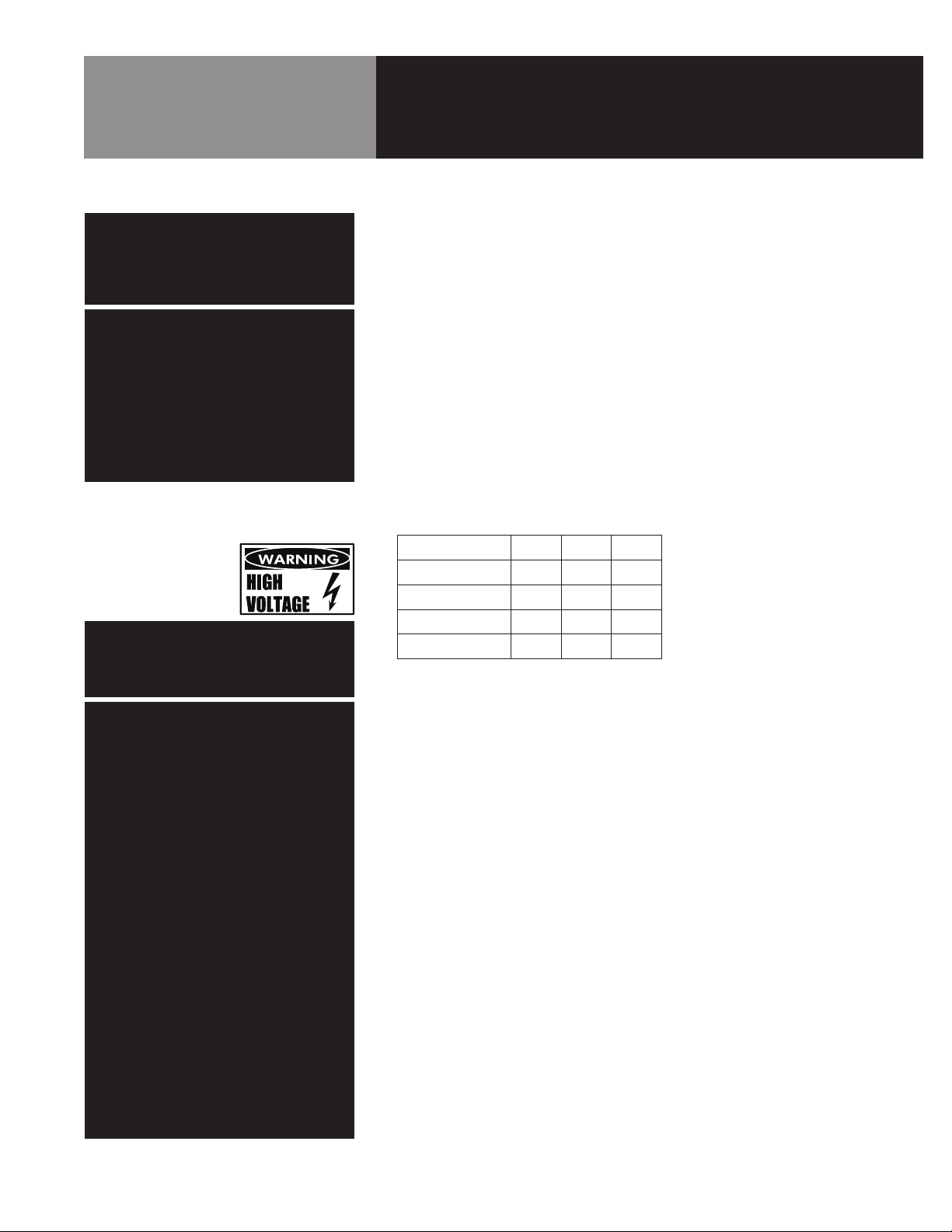
1. The WaterJet must be supplied with power as follows:
Supply Voltage
Amperes (MFS)
Herz
Phase
Amp Draw
2. Follow local codes or the National Electrical Code (NEC) to select the proper size wire to the
unit.
3. Make watertight conduit connections for the electrical supply through the control panels in
the rear of the unit. Be sure to maintain the watertight seal in the box.
4. Attach each phase leg as shown marked inside the control panels.
5. Make a watertight conduit connection at the marked opening inside the main Control Box
for the temperature chart recorder through the control panel in the rear of the unit. Be sure
to maintain the watertight seal in the box.
6. An electrical schematic of the WaterJet Control Panel and chart recorder connections is
provided at the rear of this manual, and on the inside of the main Control Box. The refrigeration unit electrical schematic can be found on the inside panel of the control box.
7. Double-check the wiring phase legs to ensure that they are attached to the correct terminal
on the terminal block.
208 240 480
30 30 20
60 60 60
3 3 3
21 21 15
LOCAL CODES AND/OR THE NATIONAL
ELECTRICAL CODE SHOULD BE
OBSERVED IN ACCORDANCE WITH
ANSI/NFPH-70-1987
(OR THE LATEST EDITION).
SUPPLY VOLTAGE AND UNIT VOLTAGE
MUST MATCH. FAILURE TO SUPPLY
UNIT WITH PROPER VOLTAGE WILL
RESULT IN EQUIPMENT DAMAGE.
OM-WJ100-CC 5
Page 6

Installation
8. The refrigeration unit must be supplied with power as follows:
a. Air Condensing Units
Supply Voltage
Fuse Amps
Herz
Phase
Amp Draw (RLA)
b. Water Condensing Units
Supply Voltage
Fuse Amps
Herz
Phase
Amp Draw (RLA)
c. For other voltages and frequencies, contact the factory.
208 240 480
125 125 60
60 60 60
3 3 3
66.8 66.8 31.4
208 240 480
125 125 60
60 60 60
3 3 3
59.6 59.6 29
WATER CONNECTIONS
CAUTION
PIPING CONNECTIONS AND
INSTALLATION MUST BE MADE BY
A QUALIFIED INSTALLER. IMPROPER
INSTALLATION CAN CAUSE DAMAGE
TO THE EQUIPMENT.
LOCAL CODES AND/OR NATIONAL
PLUMBING CODES MUST BE
OBSERVED WHEN MAKING
CONNECTIONS TO THE WATERJET.
HOT WATER SUPPLY MUST NOT
EXCEED 49º C (120º F). EXCESSIVE
HEAT CAN DAMAGE VALVE SOLENOIDS.
DRAIN CONNECTION
WARNING
BACTERIAL HAZARD! IMPROPER
INSTALLATION COULD RESULT IN
IMPROPER DRAINAGE, AND ALLOW
DRAIN MATERIAL INTO THE UNIT.
1. The WaterJet has a maximum water capacity of 1325 liters (350 gallons). Water pressure
from the supply needs to be between 2.07 bar (30 PSI) and 4.14 bar (60 PSI).
2. There are two 3/4 inch NPT water solenoid connections at the rear of the WaterJet. These
connections are for hot and cold water as labeled.
3. If hot water is not to be used, also supply the hot water solenoid inlet with cold water. Both
solenoids should be connected to cold water under such circumstances, or the unit will not
work.
1. Connect the drain at the rear of the unit using a 1-1/2 inch NPT pipe. Do not use plastic or
PVC-type pipe.
2. Install the drain line with a constant downward pitch. Ensure that there is a vertical air gap
of at least two inches from the top of the drain unless otherwise specified by codes.
3. The WaterJet has a maximum drain rate of 284 liters (75 gallons) per minute. If the building
drain is slower than the WaterJet drain, the two inch drain line may need to be restricted to
a smaller diameter compatible with the building drain and the drain time will be lengthened.
CAUTION
PIPING CONNECTIONS MUST BE MADE
BY A QUALIFIED INSTALLER. IMPROPER
INSTALLATION CAN CAUSE EQUIPMENT
DAMAGE. LOCAL CODES AND/OR
NATIONAL PLUMBING CODES MUST BE
OBSERVED WHEN MAKING PLUMBING
CONNECTIONS TO THE UNIT.
6 OM-WJ100-CC
Page 7

Installation
STEAM CONNECTIONS
SKIP THIS SECTION IF COOKING
OPERATIONS WILL NOT BE REQUIRED
WARNING
DO NOT ATTEMPT TO OPERATE
THE UNIT UNTIL QUALIFIED GROEN
INSTALLERS MAKE NECESSARY
REFRIGERATION ADJUSTMENTS.
REFRIGERATION CONNECTIONS
WARNING
DO NOT ATTEMPT TO OPERATE THE UNIT
UNTIL QUALIFIED GROEN INSTALLERS
MAKE NECESSARY REFRIGERATION
ADJUSTMENTS. (INSTALLER MUST BE
R.S.E.S. CERTIFIED).
1. The steam system is ASME shop inspected, stamped (PP) and registered with the National
Board for operation up to a maximum working pressure of 90 PSIG.
2. Connect the steam supply to the labeled 3/4” NPT connection at the safety relief valve
located on the rear of the WaterJet.
3. Recommended boiler capacity should be nine (± two) BHP.
4. Connect the condensate return line to the labeled 3/4” NPT pipe connection which is found
directly under the steam input line.
5. Globe valves (shut-off valves) are not provided with the unit, but should be installed as
required.
1. Connect refrigeration lines (Suction, Liquid and Hot Gas) as labeled at the rear of the unit.
2. Refrigeration unit must be no more than 100 feet of piping.
3. The 1-5/8” suction line, 7/8” liquid line and the 7/8” hot gas line should be welded with
nitrogen-purging during all brazing connections.
4. The suction line must have traps for every rise of 10 feet. In addition, all horizontal runs
must have a slope of not less than one inch for every 10 feet in the direction of the condensing unit.
5. Mineral oil must be added to the unit.
6. A 39 pound pre-charge of R22 is required for the condensing unit. An additional charge
must be added dependent on the line length from the condensor to the WaterJet.
Before Replacing Rear Covers on the Unit:
1. Run the WaterJet through a few cycles before replacing covers. This can be done without
food being prepared or placed in the unit. These “practice runs” will help identify any latent
installation problems such as:
a. Improper motor rotation due to improper phase wiring.
b. Loose solder connections which cause solenoid valves to stay open.
c. Leaks in any of the connections.
Initial Start-Up
1. Do not attempt to operate the unit until a qualified R.S.E.S. Certified Groen installer has
completed the necessary refrigeration adjustments.
2. The Groen installer will instruct the facility supervisor on the proper start-up procedure and
provide additional instructions as needed.
OM-WJ100-CC 7
Page 8
WARNING
DOORS WILL BE HOT WHEN UNIT IS
COOKING OR RETHERMING. CONTACT
CAN CAUSE SEVERE BURNS.
IMPROPER INSTALLATION OR
TIGHTENING OF FITTINGS CAN RESULT
IN HOT WATER LEAKS.
WARNING
STEAM ESCAPES WHEN THE DOORS
ARE OPENED. CONTACT CAN
CAUSE SEVERE BURNS.
Operation
Intended Use
Hot water supply is used to accelerate cooking or retherming times. Steam supply of nine Bhp
(± two) is required to obtain and maintain temperatures for proper and safe cooking. Retherming cycles may require some preheat time, depending on the type of food being warmed and
the steam supply.
The WaterJet is intended to chill 100 gallons of casing product. It is intended to cook up to 500
lbs of meat per cycle. Individual meat size can be up to 10 lbs.
Casings should be filled and sized so that the bags may be folded around a temperature probe,
to measure internal product temperatures.
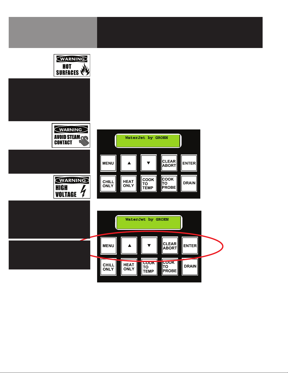
PROGRAMMING & CHILL TEMPERATURE SET (Graphic Representation)
Once turned on, the WaterJet 100 is programmed and run from the Operator’s Console:
WARNING
DISCONNECT POWER BEFORE
SERVICING THE WATERJET.
ONLY REPLACE COMPONENTS WITH
GROEN PARTS NON-GROEN PARTS
COULD RESULT IN ELECTRICAL SHOCK.
CAUTION
DO NOT CLOSE SUCTION LINE VALVE.
FAILURE TO KEEP VALVE OPEN DURING
OPERATION WILL CAUSE THE
EVAPORATION TO LEAK.
The unit is programmed using the upper row of controls:
The paragraphs which follow describe the use of these touch pads.
8 OM-WJ100-CC
Page 9

Operation
START-UP
When first initialized, Press MENU
1. “CHILL SETUP” will be displayed.
Press ENTER
2. “TEMPERATURE IN DEGREES F” will be displayed (Pressing the up or down arrow at this
point changes the default from Fahrenheit to Celsius and back).
Press ENTER
3. “WATER TEMP 34’ ” will be displayed.
Press UP ARROW
4. “WATER TEMPERATURE 35’ ” will be displayed
Press ENTER.
5. “WATERJET BY GROEN” will be displayed.
This sets the chilling temperature to 35 degrees F. Fahrenheit is always the default but can
be changed at step 2 by using the up or down arrow keys.
This setup function from MENU sets the chill temperature for the “CHILL ONLY” function.
Once the unit is set to 35 degrees (with temperature in Fahrenheit) there should be no
further need to change the setting.
OM-WJ100-CC 9
Page 10

Operation
Press MENU
1. “CHILL SETUP” will be displayed.
Press UP ARROW
2. “RETHERM SETUP” will be displayed.
Press ENTER
3. “TEMPERATURE IN DEGREES F” will be displayed.
Press ENTER
4. “WATER TEMPERATURE 130ºF ” will be displayed
10 OM-WJ100-CC
Press UP or DOWN ARROW button to change to the temperature.
Press ENTER.
5. “WATERJET BY GROEN” will be displayed.
This sets the rethermalization temperature in the “HEAT ONLY” mode. Fahrenheit is always
the default but can be changed at step 2, by using the up or down arrow keys. The temperature setting for rethermalization can be changed here when there is a need to increase
or decrease these temperatures.
Page 11

Operation
CHILL
RETHERM
COOK TO TIME
Press CHILL ONLY to start
Press CHILL ONLY to stop
1. The unit will chill to the temperature set in the CHILL SETUP (35 F). The unit will display the
temperature in the tank while running.
Press HEAT ONLY to start
Press HEAT ONLY to stop
1. The unit will retherm to the temperature set in the RETHERM SETUP. The unit will display the
current, changing temperature in the tank while running.
Press COOK TO TIME to start.
1. “TEMP IN DEGREES F” will be displayed.
(Press up or down ARROW to change to degrees C)
Press ENTER
2. “SOAK WATER TEMP” will be displayed
(Press up or down ARROW to change to the desired thaw temperature)
Press ENTER
3. “SOAK TIME IN MINUTES” will be displayed
(Press up or down ARROW to change to the desired thaw time)
REMEMBER! The time function only starts after the unit reaches the set temperature!
Keep at “0” if no thaw time is desired.
Press ENTER
OM-WJ100-CC 11
Page 12

Operation
4. “COOK WATER TEMP’ will be displayed
(Press up or down ARROW to change to the desired cooking temperature)
Press ENTER
5. “COOK TIME IN MINUTES” will be displayed
(Press up or down ARROW to change to the desired cooking time)
REMEMBER! The time function only starts after the unit reaches the set temperature!
Press ENTER
6. “CHILL WATER TEMP’ will be displayed.
(Press up or down ARROW to change to the desired chilling temperature (35ºF))
COOK TO PROBE
Press ENTER
Press COOK TO TIME to stop
If the display has the desired time or temperature already displayed just press ENTER. The
CHILL temperature should never be set lower than 35 F.
Press COOK TO PROBE to start.
1. “TEMP IN DEGREES F” will be displayed.
(Press up or down ARROW to change to degrees C)
Press ENTER
2. “SOAK WATER TEMP” will be displayed
(Press up or down ARROW to change to the desired thaw temperature)
Press ENTER
12 OM-WJ100-CC
Page 13

Operation
3. “SOAK TIME IN MINUTES” will be displayed.
(Press up or down ARROW to change to the desired thaw time. Keep at “0” if no thaw time is desired)
Press ENTER
4. “COOK WATER TEMP’ will be displayed
(Press up or down ARROW to change to the desired tank temperature)
Press ENTER
5. “COOK PROBE TEMP’ will be displayed
(Press up or down ARROW to change to the desired probe temperature)
Press ENTER
6. “COOK TIME IN MINUTES” will be displayed
(Press up or down ARROW to change to the desired cooking time)
REMEMBER! The time function only starts after the unit reaches the set temperature!
Press ENTER
7. “CHILL WATER TEMP’ will be displayed
(Press up or down ARROW to change to the desired chilling temperature (35 F))
Press ENTER
Press COOK TO PROBE to stop
If the display has the desired time or temperature already displayed just press ENTER. The
CHILL temperature should never be set lower than 35 F.
REMEMBER! The time function only starts after the unit reaches the set temperature!
REMEMBER! Cook times have to be at least 1 minute.
REMEMBER! The unit will not let you drain manually while it is running.
OM-WJ100-CC 13
Page 14

Operation
BROKEN BAG CLEANING
WARNING
BEFORE HANDLING ANY CLEANING
PRODUCT, WEAR RUBBER GLOVES,
PROTECTIVE CLOTHING,
AND A FACE SHIELD.
WARNING
NEVER ADD ANY OTHER CHEMICALS
TO THE TANK WHEN
CIR-KLENZ IS PRESENT.
1. Drain the tank completely
2. Remove the lifting platform from the tank
3. Using a wet/dry vacuum, vacuum out large particles of food from the tank and platform
4. Use a brush to clean food particles from in between heat exchanger plates
5. Remove clean-out plate from pump supply duct
6. Use a brush to clean food particles out of the duct
7. Replace the platform in the tank
8. Replace the clean out plate on the supply duct
9. Fill to high water mark with fresh, cool water
10. Add Cir-Klenz II to the tank as follows:
WJ100-C - use 1 gallon
WJ100-CC - use 3 quarts
11. If the Water Jet has heating capability, heat the tank water to 145F
12. Run the recirculation pump for 10 minutes. (Cir-Klenz is low foaming)
13. Wearing a rubber glove, wipe all around the inside surface of the tank at water level with a
soft cloth to remove any food particles
14. Drain the tank, and refill to the high water mark with fresh, cool water
15. Run the recirculation pump for at least one minute
16. Drain the tank
ROUTINE CLEANING
WARNING
BEFORE HANDLING ANY CLEANING
PRODUCT, WEAR RUBBER GLOVES,
PROTECTIVE CLOTHING,
AND A FACE SHIELD.
WARNING
NEVER ADD ANY OTHER CHEMICALS
TO THE TANK WHEN
CIR-KLENZ IS PRESENT.
1. Weekly cleaning is recommended for regular users. For heavy users, it is recommended
that routine cleaning be performed after every 20 batches.
2. Leave the tank filled to high water mark with water
3. Add Cir-Klenz II to the tank as shown
WJ100-C - use 1 gallon
WJ100-CC - use 3 quarts
4. If the Water Jet has heating capability, heat the tank water to
5. Run the recirculation pump for 10 minutes. (Cir-Klenz is low foaming)
6. Wearing a rubber glove, wipe all around the inside surface of the tank at water level with a
soft cloth to remove any food particles
7. Drain the tank, and refill to the high water mark with fresh, cool water
8. Run the recirculation pump for at least one minute
9. Drain the tank
14 OM-WJ100-CC
Page 15

Operation
DE-LIMING
WARNING
BEFORE HANDLING ANY CLEANING
PRODUCT, WEAR RUBBER GLOVES,
PROTECTIVE CLOTHING,
AND A FACE SHIELD.
SANITIZING
WARNING
BEFORE HANDLING ANY CLEANING
PRODUCT, WEAR RUBBER GLOVES,
PROTECTIVE CLOTHING,
AND A FACE SHIELD.
WARNING
NEVER ADD ANY OTHER CHEMICALS
TO THE TANK WHEN
CIR-KLENZ IS PRESENT.
1. De-lime as necessary to remove scaling or calcification from tank interior
2. Fill tank with cool water to high water mark
3. Add EcoLabs PL-3 to the tank:
For water with Less than 20 grains Hardness use ½ gallon
For water with more than 20 grain
Hardness or High Ironuse three quarts
4. There is no need to heat the water. Run the re-circulation pump for at least 10 minutes
5. Drain the tank
6. There is no need to do a rinse cycle
7. Heavy lime build up may require multiple applications or scrubbing to remove scale.
1. Sanitizing is recommended each time the tank is filled
2. Fill tank to low water mark with cool water
3. Add 32 ounces of Vortexx to the tank
4. Run the recirculation pump for at least 5 minutes
5. There is no need to drain the water after sanitizing
6. There is no need to rinse after sanitizing
NOTE
GROEN RECOMMENDS THAT THE TANK
BE DRAINED AT THE END OF EACH
PRODUCTION DAY.
OM-WJ100-CC 15
Page 16

Maintenance
BROKEN BAG CLEANING
WARNING
USE OF REPLACEMENT PARTS OTHER
THAN THOSE SUPPLIED BY GROEN OR
THEIR AUTHORIZED DISTRIBUTORS
CAN CAUSE INJURY TO THE OPERATOR
AND DAMAGE TO THE EQUIPMENT AND
WILL VOID ALL WARRANTIES. SERVICE
PERFORMED BY OTHER THAN
FACTORY-AUTHORIZED PERSONNEL
WILL VOID ALL WARRANTIES.
CAUTION
THE FOLLOWING WORK MUST BE
PERFORMED BY A CERTIFIED RSES
(REFRIGERATION SERVICE ENGINEERS
SOCIETY) TECHNICIAN.
WARNING
ELECTRICAL POWER MUST BE SHUT OFF
BEFORE WORK IS DONE ON INTERNAL
COMPONENTS. ELECTRICAL SHOCKS
AND BURNS COULD RESULT.
Your WaterJet is designed to require minimum maintenance, but some parts may require
replacement after prolonged use. After installation, no user adjustment should be necessary. If
a service need arises, only authorized personnel should perform the work.
The WaterJet motor must be greased every six months. The grease fitting is located near the
top of the motor opposite the pump.
Factory installed NLGI #2 type food grade grease was initially used in the motor. Approved
sources are Chevron SRI #2 and Shell Oil Dolium-R. Do not use any other type of grease.
Incompatible greases will cause the motor to fail.
The refrigeration system filter dryers must be changed within the first two weeks of operation.
Thereafter they must be changed whenever the system has been opened to the atmosphere.
Service personnel should check the unit at least once a year. This should include inspecting
wires and connections and cleaning inside the control console. A Maintenance and Service Log
is provided at the rear of this manual. Each time work is performed, enter the date on which it
was done, what was done, and who did it.
16 OM-WJ100-CC
Page 17

Troubleshooting
Your CapKold WaterJet 100 will operate smoothly and efficiently if properly maintained. However, the following is a list of checks to make in the event
of a problem. If the actions suggested do not solve the problem, call your authorized Groen Service Representative. For the phone number of the
nearest agency, call your area Groen representative or the Groen Parts and Service Department. If an item on the list is followed by X, the work should
only be performed by a qualified service representative.
WARNING
USE OF ANY REPLACEMENT PARTS OTHER THAN THOSE SUPPLIED BY GROEN OR THEIR AUTHORIZED DISTRIBUTORS CAN CAUSE INJURY
TO THE OPERATOR AND DAMAGE TO THE EQUIPMENT AND WILL VOID ALL WARRANTIES.
SYMPTOM WHO WHAT TO CHECK
User
Unit will not heat
ASA only
a. Steam supply not on
b. Steam connection for leaks
c. Open circuit on solenoid connection
d. Solenoid not seated correctly
e. Refrigeration valve open
Unit will not stop heating ASA only
User a. Refrigeration valves at WaterJet are closed
Unit will not cool
Pump is not working
- No water flow
- Low water flow
Pump/Motor making loud,
squeaking or clanging noise
No water fill
Water does not stop filling
Tank will not drain
ASA only
User
ASA only
ASA only
User
ASA only
User a. Clean water level probes
ASA only
User a. Drain valve clogged
ASA only b. Open circuit or short in circuits
a. Solenoid valve needs cleaning (generally trash from installation)
b. Electrical short
b. Refrigeration problem
c. Steam valve open
d. Open circuit on solenoid
e. Solenoid not seated properly
a. Water probes are dirty
b. Diverter not set correctly
c. Lift circuits are bad - possible sensor failure
d. Water level board may not be functioning
e. Motor overload
f. Low current, wrong voltage
g. Temperature sensor bad
h. Faulty door sensors
i. Motor starter failed
a. Low or no grease in motor
b. Foreign object(s) in pump
a. Water supply not turned on
b. Leak in water supply line
c. Opener short circuit on solenoid
d. Solenoid improperly seated
b. Solenoid valve needs cleaning (generally trash from installation)
c. Open circuit on solenoid
OM-WJ100-CC 17
Page 18

SYMPTOM WHO WHAT TO CHECK
User a. Controls locked up. Turn unit off, then back on again.
Controls will not respond
ASA only
Lift not moving ASA only
User
Horn/Buzzer sounds
continuously
ASA only
Unit not functioning as
programmed
ASA only
Troubleshooting
b. Control failure (lightning strike, power surge, other)
c. Battery bad
a. Gearing broken
b. System out of position or frozen
a. Close door while heating or cooking
b. Move lift to fully down position
c. Motor overload failure
d. Buzzer failure
a. Temperature probe failure
b. Open or short across temperature probes
18 OM-WJ100-CC
Page 19
Parts List
OM-WJ100-CC 19
Page 20
Parts List
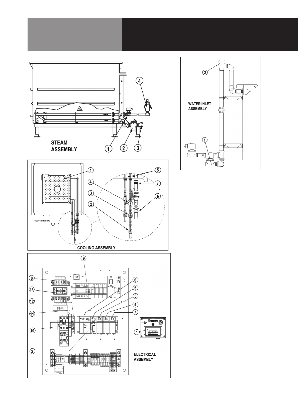
Part Description CapKold P/N Key
125308 – COOLING ASSEMBLY
Plate evaporator 125314 1
Valve, ball 7/8”ODF w/service 125041 2
Valve Solenoid Refrigerant 7/8 OD 125513 3
Valve, expansion 125040 4
Bulkhead fitting 7/8” 125335 5
Valve, ball 1 5/8”ODF w/service 125042 6
Connector, male pipe 1 1/2” 125515 7
133624 – ELECTRICAL ASSEMBLY
Display, Operator Console 125273 1
Connector DIN for Asco Solenoids 125207 x
Probe Meat Thermometer 125090 x
Probe, temperature 133686 x
Thermostat, Sensor 133692 x
Pen Purple N102726 y
Pen Red N102727 y
Chart Recorder 129220 z
Magnetic door sensor Switch 125476 x
Battery, PLC 133728 2
Module, 12 Outputs 125253 3
Module, 8 inputs 125252 4
CPU Module, PLC 125251 5
Power Supply, PLC 125250 6
Module, 4 RTD inputs 125254 7
Transformer 125241 8
Power Supply 120VAC 125614 9
Starter w/Overload sensor 125243 10
Circuit Breaker 5 AMP 125611 11
Circuit Breaker 3 AMP 125246 12
Fuse, 6 AMP 119823 13
125348 – PLATFORM ASSEMBLY
133764 – WATERJET 100 LID ASSY
Spring, Gas - 316 SS 125470 -
125302 – STEAM ASSY, WJ100
Valve Solenoid 3/4”NPT Steam 125107 Trap Steam Bucket Type 004050 Valve, Swing Check 005515 Valve safety release 3/4”NPT 098158 -
133434 – WATER INLET ASSEMBLY
Valve, Solenoid 3/4” NPT 2 way 125107 Vacuum breaker 3/4” 125585 -
20 OM-WJ100-CC
Page 21

Recirculation Assembly
Parts List
Part Description CapKold P/N Key
133732 – RECIRCULATION ASSEMBLY
Pump and Motor Assembly 133693 1
Seal, Motor shaft 133700 Pump Casing, Sanitary 133703 Pump Impeller 133704 Casing Gasket 133706 Seal, Pump, Carbon 133709 O-ring for Pump Seal 133711 Duct, Bottom Return Assembly 133662 2
Gasket, cover plate, return duct 133683 Gasket 6” Triclover N64489 3
Gasket 8” Triclover N96054 4
Gasket 4” Triclover 053331 5
Valve, diverter 133600 6
Valve/Acutator Assy 24 VDC 133684 7
Overflow Hose Assy 133729 8
Gasket 2” Triclover 016602 9
OM-WJ100-CC 21
Page 22

Wiring Schematic
22 OM-WJ100-CC
Page 23

Service Log
Model No: Purchased From:
Serial No: Location:
Date Purchased: Date Installed:
Purchase Order No: For Service Call:
Date Maintenance Performed Performed By
OM-WJ100-CC 23
Page 24

1055 Mendell Davis Drive • Jackson MS 39272
888-994-7636 • 601-372-3903 • Fax 888-864-7636
unifiedbrands.net
© 2014 Unified Brands. All Rights Reserved. Unified Brands is a wholly-owned subsidiary of Dover Corporation.
PART NUMBER 172043 REV. A (10/14)
 Loading...