

Page 1
OPERATORMANUAL
IMPORTANTINFORMATION,KEEPFOROPERATOR
This manual provides information for:
MODELSVRC-3E
&VRC-6E
Domestic
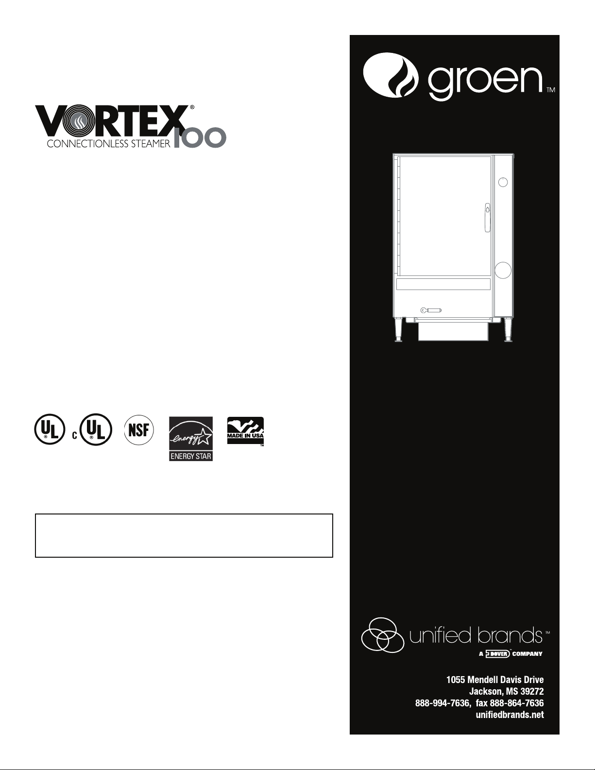
VORTEX100®
CONNECTIONLESS
STEAMER
· Self Contained
· Electric Heated
· Capacity: VRC-3E=3 Steamer Pans Per Cavity
VRC-6E=6 Steamer Pans Per Cavity
THISMANUALMUSTBERETAINEDFORFUTUREREFERENCE.
READ, UNDERSTAND AND FOLLOW THE INSTRUCTIONS AND
WARNINGSCONTAINEDINTHISMANUAL.
FORYOURSAFETY
Do not store or use gasoline or other flammable vapors
and liquids in the vicinity of this or any other appliance.
NOTIFYCARRIEROFDAMAGEATONCE
Itistheresponsibilityoftheconsigneetoinspectthecontaineruponreceiptof
sameandtodeterminethepossibilityofanydamage,includingconcealeddam-
age.Unified Brandssuggests that if you aresuspiciousofdamagetomakea
notationonthedeliveryreceipt.Itwillbetheresponsibilityoftheconsigneetofile
aclaimwiththecarrier.Werecommendthatyoudosoatonce.
ManufactureService/Questions888-994-7636.
Information contained in this document is known to be current and accurate at the time
of printing/creation. Unified Brands recommends referencing our product line websites,
unifiedbrands.net, for the most updated product information and specifications.
PART NUMBER 148673, REV. M (06/15)
PART NUMBER 148673, REV. G (09/07)
Page 2

IMPORTANT - READ FIRST - IMPORTANT
WARNING: WHEN YOU OPEN THE DOOR, STAY AWAY FROM STEAM COMING OUT OF THE UNIT.
STEAM CAN CAUSE BURNS.
WARNING: BEFORE CLEANING THE OUTSIDE OF THE STEAMER, DISCONNECT THE ELECTRIC
POWER SUPPLY. KEEP WATER AND CLEANING SOLUTIONS OUT OF CONTROLS AND
ELECTRICAL COMPONENTS. NEVER HOSE OR STEAM CLEAN ANY PART OF THE UNIT.
WARNING: ALLOW COOKING CHAMBER TO COOL BEFORE CLEANING.
WARNING: DO NOT MOVE THE UNIT WITH WATER IN THE CAVITY OR DRAIN PAN.
WARNING: ALLOW WATER IN DRAIN PAN TO COOL BEFORE EMPTYING.
WARNING: DO NOT PUT HANDS OR TOOLS INTO THE COOKING CHAMBER UNTIL THE FAN HAS
STOPPED T
URNING.
WARNING: DO NOT OPERATE THE UNIT UNLESS THE REMOVABLE RIGHT SIDE PANEL HAS BEEN
RETURNED TO ITS PROPER LOCATION.
WARNING: USE OF ANY REPLACEMENT PARTS OTHER THAN THOSE SUPPLIED BY GROEN OR THEIR
AUTHORIZED DISTRIBUTOR VOIDS ALL WARRANTIES AND CAN RESULT IN BODILY
INJURY TO THE OPERATOR AND DAMAGE THE EQUIPMENT. SERVICE BY OTHER THAN
FACTORY-AUTHORIZED PERSONNEL WILL VOID ALL WARRANTIES.
WARNING: HIGH VOLTAGE EXISTS INSIDE CONTROL COMPARTMENTS. DISCONNECT FROM BRANCH
CIRCUIT BEFORE SERVICING. FAILURE TO DO SO CAN RESULT IN SERIOUS INJURY OR
DEATH.
WARNING: DO NOT USE CHEMICALS OTHER THAN MILD DETERGENTS TO CLEAN THE COOKING
CHAMBER
.
WARNING: CAREFULLY READ THE OPERATION INSTRUCTION LABEL BEFORE OPERATION OF THE
UNIT.
WARNING: DO NOT USE REVERSE OSMOSIS (RO) OR DISTILLED WATER IN THE STEAMER.
CAUT
ION: SHIPPING STRAPS ARE UNDER TENSION AND CAN SNAP BACK WHEN CUT.
CAUTION: DO NOT INSTALL UNITS WITHIN 2 INCHES OF A HEAT SOURCE SUCH AS A BRAISING PAN,
DEEP FRYER, CHAR BROILER OR KETTLE.
NOTICE: DO NOT USE ANY DE-GREASER THAT CONTAINS POTASSIUM HYDROXIDE OR SODIUM
HYDROXIDE OR THAT IS ALKALINE.
OM-VRC-3E/VRC-6E
2 OM-VRC-3E/VRC-6E 148673 REV. G
Page 3

148673 REV. G OM-VRC-3E/VRC-6E 3
Table of Contents
OPERATOR WARNINGS . . . . . . . . . . . . . . . . . . . . . . . . . . . . . . . . . . . . . . . . . . . . . . . . . . . . . . . . . . . . . . . . . . . . 2
REFERENCES . . . . . . . . . . . . . . . . . . . . . . . . . . . . . . . . . . . . . . . . . . . . . . . . . . . . . . . . . . . . . . . . . . . . . . . . . . . . . 3
EQUIPMENT DESCRIPTION . . . . . . . . . . . . . . . . . . . . . . . . . . . . . . . . . . . . . . . . . . . . . . . . . . . . . . . . . . . . . . . . . 4
INSPECTION AND UNPACKING . . . . . . . . . . . . . . . . . . . . . . . . . . . . . . . . . . . . . . . . . . . . . . . . . . . . . . . . . . . . . . 4
INSTALLATION AND START-UP . . . . . . . . . . . . . . . . . . . . .
. . . . . . . . . . . . . . . . . . . . . . . . . . . . . . . . . . . . . . . 5-6
OPERATION . . . . . . . . . . . . . . . . . . . . . . . . . . . . . . . . . . . . . . . . . . . . . . . . . . . . . . . . . . . . . . . . . . . . . . . . . . . . 8-9
CLEANING . . . . . . . . . . . . . . . . . . . . . . . . . . . . . . . . . . . . . . . . . . . . . . . . . . . . . . . . . . . . . . . . . . . . . . . . . . . . . . . 10
MAINTENANCE . . . . . . . . . . . . . . . . . . . . . . . . . . . . . . . . . . . . . . . . . . . . . . . . . . . . . . . . . . . . . . . . . . . . . . . . . . . 11
TROUBLESHOOTING . . . . . . . . . . . . . . . . . . . . . . . . . . . . . . . . . . . . . . . . . . . . . . . . . . . . . . . . . . . . . . . . . . . . . . 11
DRAIN KIT
INSTALLATION INSTRUCTIONS
. . . . . . . . . . . . . . . . . . . . . . . . . . . . . . . . . . . . . . .
.
DRAIN KIT DIAGRAM
. . . . . . . . . . . . . . . . . . . . . . . . . . . . . . . . . . . . . . . . . . . . . . . . . . . . . . . . .
.
RACKS, PAN INSTALLATION INSTRUCTIONS . . . . . . . . . . . . . . . . . . . . . . . . . . . . . . . . . . . . . . . . . . . . . . . . .
SERVICE LOG . . . . . . . . . . . . . . . . . . . . . . . . . . . . . . . . . . . . . . . . . . . . . . . . . . . . . . . . . . . . . . . . . . . . . . . . . . . .
References
UNDERWRITERS LABORATORIES, INC.
333 Pfingsten Road
Northbrook, Illinois 60062
NFPA/70 The National Electrical Code
NATIONAL SANITATION FOUNDATION
3475 Plymouth Road
Ann Arbor, Michigan 4
8106
NATIONAL FIRE PROTECTION ASSOCIATION
60 Batterymarch Park
Quincy, Massachusetts 02269
Website Address: www.groen.com
12
13
14
15
. . . . . . . . . . . . . . . . . . . . . . . . . . . . . . . . . . . . . . . . . . . . . . . . . . . . . . . . . . . . . . . .
WARRANTY PROTECTION
16-17
OM-VRC-3E/VRC-6E
Table of Contents
OPERATOR WARNINGS ......................................................................................................................................... 2
REFERENCES ......................................................................................................................................................... 3
EQUIPMENT DESCRIPTION ................................................................................................................................... 4
INSPECTION AND UNPACKING ............................................................................................................................ 4
INSTALLATION AND STARTUP ..........................................................................................................................5-6
OPERATION .........................................................................................................................................................8-9
CLEANING ............................................................................................................................................................. 10
MAINTENANCE ..................................................................................................................................................... 11
TROUBLESHOOTING ........................................................................................................................................... 11
DRAIN KIT INSTALLATION INSTRUCTIONS ...................................................................................................... 12
DRAIN KIT DIAGRAM ........................................................................................................................................... 13
RACKS, PAN INSTALLATION INSTRUCTIONS ................................................................................................... 14
PARTS LIST ...................................................................................................................................................... 15-16
WIRING DIAGRAM ................................................................................................................................................ 17
ELEMENT WIRING DIAGRAM ......................................................................................................................... 18-20
SERVICE LOG ....................................................................................................................................................... 21
WARRANTY PROTECTION ............................................................................................................................. 22-23
NSF INTERNATIONAL
789 N. Dixboro Rd.
P.O. Box 130140
Ann Arbor, Michigan 48113-0140
Page 4
Equipment Description
Your Groen VRC-3E or VRC-6E Vortex
Connectionless Steamer is designed to give years
of service. It has a stainless steel cavity (cooking
chamber) which is served by an inside water
reservoir which is electrically heated. A powerful
blower circulates the steam in the cavity to increase
heating efficiency.
The cavity holds up to three (VRC-3E) or six (VRC6E) steam table pans (12" x 20" x 2½" deep). An 18
gauge stainless steel case encloses the cavity and
the contr
ol compartment that houses electrical
components. Door hinges are reversible (the door
may be set to open from the left or right). Operating
Controls are on the front panel.
VRC-3E and VRC-6E steamers are equipped with
fully electronic controls. These units are readily
identified by their unique control panels. A rocker
switch is used to turn the unit on and off.
WARNING
DISCONNECT ELECTRICAL POWER BEFORE
CHANGING FUSES. FAILURE TO DO SO WILL
CAUSE ELECTRICAL SHOCK OR DEATH.
The VRC-3E holds three standard 12"x 20"x 2
-1/2"
or two 12"x20"x4" steamer pans.
The VRC-6E holds up to six standard
12"x20"x2-1/2" or four 12"x20x4" steamer pans.
Inspection and Unpacking
The Steamer will be delivered completely assembled
in a heavy shipping carton strapped to a skid. On
receipt, inspect carton carefully for exterior damage.
If damage is evident, notify the local carrier
immediately and file a damage claim. Groen
assumes no liability for damage incurred in transit.
Reconfirm that the voltage at the loc
ation is
compatible with the steamer you received.
CAUTION
SHIPPING STRAPS ARE UNDER TENSION AND
CAN SNAP BACK WHEN CUT.
Carefully cut the straps and detach the sides of the
carton from the skid. Pull the carton up off the unit.
Be careful to avoid personal injury or equipment
damage from staples which might be left in the carton
walls.
CAUTION
THE VRC-3E WEIGHS 150 POUNDS (68 KG).
THE VRC-6E WEIGHS 170 POUNDS (77 KG).
YOU SHOULD GET HELP AS NEEDED TO LIFT
THIS WEIGHT SAFELY.
Write down the model number, se
rial number and
installation date. Keep this information for reference.
Space for these entries is provided at the top of the
Service Log in the back of this manual.
When starting installation, check packing materials
to make sure loose parts such as the drain pan and drip
tray are not discarded with this material.
OM-VRC-3E/VRC-6E
4 OM-VRC-3E/VRC-6E 148673 REV. G
Page 5
WARNING
GROUNDING INSTRUCTIONS: THIS APPLIANCE MUST BE CONNECTED TO A GROUNDED
METALLIC, PERMANENT WIRING SYSTEM, OR AN EQUIPMENT GROUNDING
CONDUCTOR MUST BE RUN WITH THE CIRCUIT CONDUCTORS AND CONNECTED TO
THE EQUIPMENT GROUNDING TERMINAL ON THE STATION.
Installation and Start-Up
CAUTION
DO NOT INSTALL THE UNIT WITHIN 2 INCHES OF A HEAT SOURCE (SUCH AS A BRAISING PAN, DEEP FAT
FRYER, CHARBROILER OR KETTLE).
Electrical Supply Connection - Observe all local, national, or other applicable codes.
Three phase models of the Vortex™ Connectionless
Steamer are supplied with a cord set ready to be
connected to a power supply. See the chart below
for the correct matching receptacle (not s upplied with
the unit).
Single phase models are designed to be directly
connected (hard wired) to the electrical supply a
nd
allow sufficient loop in the flexible conduit to facilitate
inspection, servicing, and cleaning.
Branch Circuit Protection
Each Steamer, including individual units of stacked
models, should have its own branch circuit protection
and ground wire. Current and power demands for
each unit are as shown below.
ELECTRICAL SUPPLY CONNECTIONS
FIELD WIRING TABLE - USE COPPER WIRE ONLY - INSULATION RATING (90ºC)
VOLTAGE
(60 Hz Only)
KW RATED CURRENT DEMAND
VRC-3E VRC-6E VRC-3E VRC-6E
208 3 PHASE 25 Amps
240 3 PHASE 17 Am
ps 22 Amps
480 3 PHASE 1 Amps
PLUG AND RECEPTACLE CHART
VOLTS PHASE PLUG RECEPTACLE
9KW 10KW 9KW 10KW
208 3 15-30P 15-50P 15-30R 15-50R
240 3 15-30P 15-50P 15-30R 15-50R
480 3 L16-30P L16-30P L16-30R L16-30R
208 1 ---- ---- ---- ----
240 1 ---- ---- ---- ----
OM-VRC-3E/VRC-6E
6.8 KW
6.8 KW
6.8 KW
9 KW
9 KW
9 KW
19 Amps
9 Amps 1
148673 REV. G OM-VRC-3E/VRC-6E 5
Page 6
Water Connection(s) - Units Manual Filled
No
Water Connection(s) - Units with Autofill
Make sure that the incoming water connection is made
with a 3/4” .H. COLD water hose. Rigid pipe is not
required. The water pressure should be between 30 and
60 PSIG. Higher pressures will require the use of a
pressure regulator. Make sure that all connections are
tight with no leaks - no matter how small.
Drain Line Installation - Units with Autofill
or Units with Drain Kit
The drain line should not be less than:
1 - 1/2” - for single units
2” (6E) - for double stacked units
The
re must be a 2” air gap to the (nonpressureized) building drain. Make sure that the
drain is sloped AWAY and DOWN from the
steamer and that there are no obstructions in the
line. Failure to observe these requirements may
cause a water trap in the drain line and produce
enough back pressure to prevent proper cavity
draining - resulting in condensate water leaking
from the door. Drain line must NOT be made of
plastic pipe. It must be able to wi
thstand
boiling water.
water connection is needed. The water will be
poured directly into the water cavity reservoir. Avoid
the use of any chemically treated water specifically
filtered water.
Drain Connection
The Vortex™ Connectionless Steamer should be
manually drained to the bottom containment pan
supplied by the factory. If the unit is connected to a
drain, do not connect more than two units to one
drain line or pressure from one unit will effect the
second unit.
Stacking Units Instructions
Remove drain containment pan from the bottom of
unit(s). Unscrew to remove adjustable legs from
base of Vortex unit(s). Unfasten nuts and bolts on
stand platform(s). Place Vortex unit(s) on stand
platform. Align the (4) leg holes with the holes in the
platform. Secure Vortex unit(s) to stand platform(s)
using bolts and washers provided in step 2 as shown
in detail “A” of figure 1 on page 7.
For double stack units only:
By loosening the left screw and removing the right
screw provided, moun
t steam exhaust bracket
assembly to the back panel of the top Vortex unit as
shown in detail “B” of Figure 1 on page 7. Attach the
steam exhaust hose from the bottom Vortex unit’s
steam outlet tube to the top Vortex unit’s steam
exhaust bracket assembly using hose clamps
provided as shown in figure 2 on page 7. (Note:
Steam exhaust hose may need to be cut to fit.)
Steam Vent Assembly Instructions
Remove steam diverter assembly from
literature bag which can be found inside of unit.
Slide loose end
as shown over unit steam outlet,
tighten worm gear clamp with flat head screw driver.
Be sure steam outlet is pointing in the upward
position. (Shown below)
OM-VRC-3E/VRC-6E
WARNING
DO NOT USE REVERSE OSMOSIS (RO) OR
DISTILLED WATER IN THE STEAMER.
POWER CORD
CONTAINMENT PAN
TO DIVERT STEAM OUTLET
ATTACH THIS STEAM DIVERTER
ASSEMBLY
TO THE UNIT EXHAUSTTUBE .
UNIT STEAM OUTLET
6 OM-VRC-3E/VRC-6E 148673 REV. G
Page 7
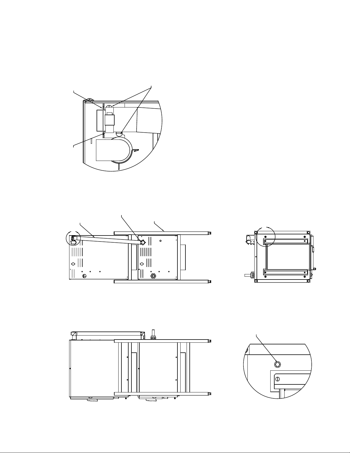
Double Stack Assembly Diagram
7
OM-VRC-3E/VRC-6E
FIGURE 1
FIGURE 2
DOUBLE STACK
STEAM EXHAUST
HOSE P/N: 141505
DOUBLE STACK STAND
P/N: 142363
HOSE CLAMPS
P/N: 073259
B
DETAIL B
SCALE 1 : 1
10-32 SCREW
P/N: 004173
DOUBLE STACK STEAM
EXHAUST BRACKET ASSEMBLY
P/N: 143243
HOSE CLAMPS
P/N: 073259
A
DETAIL A
SCALE 1 : 2
3/8-16 CAP SCREW
TO SECURE UNIT
TO STAND. P/N:
005449 TYP. (8)
PLCS.
148673 REV. G OM-VRC-3E/VRC-6E 7
Page 8
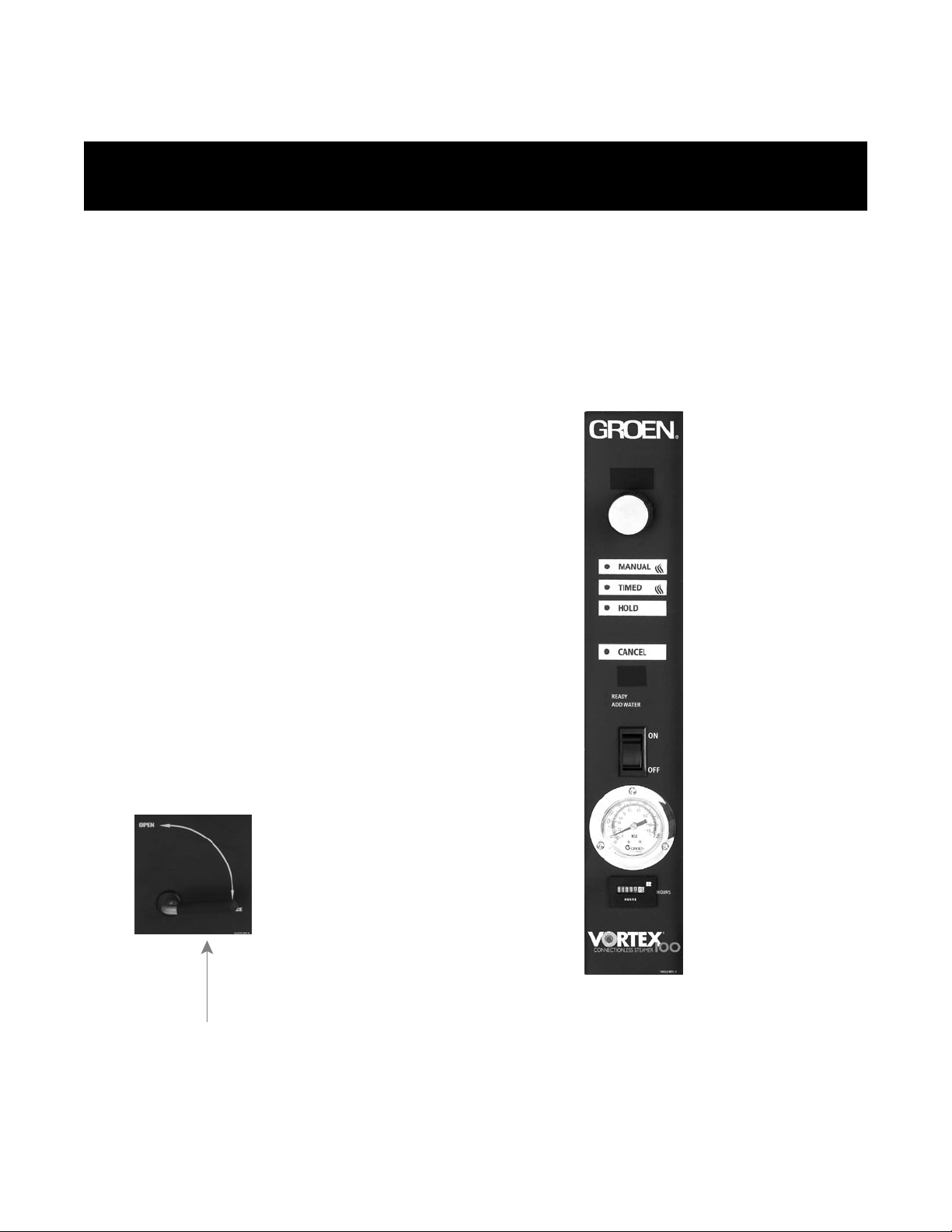
Open/Close Handle
Operation
WARNING
ANY POTENTIAL USER OF THE EQUIPMENT MUST BE TRAINED IN SAFE AND CORRECT OPERATING
PROCEDURES.
A. Controls
Operator controls are on the front right of the unit.
The VRC-3E and VRC-6E control panels have the
following touch pads and indicator lights:
! The ON/OFF rocker switch gets the
Vortex™ ready for use, or shuts it off.
! The HOLD indicator light shows that the
cavity is at holding temperature.
! The TIMED indicator light stays on
when the timer is operating.
! The ADD WATER indicator light is lit when
it’s time to add water.
! The open and closed position of the
drain valve allows the unit to be filled
with water or drained.
!
!
The ready indicator light indicate the
unit has achieved the ready temperature.
Temperature gauge indicates internal
temperature of cavity.
! Hour meter records cumulative hours of
operation.
! T
! The FAULT display shows the
current fault.
he HI TEMP (error code 6) indicator
comes on when the bottom of the water
reservoir becomes too hot.
OM-VRC-3E/VRC-6E
TIME display
TIMER knob
MANUAL button and indicator
TIMED button and indicator
HOLD button and indicator
CANCEL button and indicator
FAULT display
ON/OFF rocker switch
Temperature gauge
Hour meter
8 OM-VRC-3E/VRC-6E 148673 REV. G
Page 9

The Push Button Operations:
1 In the HOLD position the steam
generator stays at a low boil or “holding”
temperature. Factory set at 160° F.
2 When a cook time is set, the TIMED light
will illuminate. The unit steams until the
timer counts down to zero and goes into
HOLD. At that time, the HOLD light
illuminates and a beeper sounds.
3 When the MANUAL button is pushed,
4 CANCEL button should be pushed to
stop beeping.
the unit steams continuously. The green
MANUAL light will stay illuminated.
B. Operating Procedure
1. Make sure drain handle is in closed position.
With the cooking chamber water reservoir
“empty” press the ON/OFF rocker switch to ON.
The ADD WATER light will illuminate when
manual filling. Pour water into the reservoir
t
up to the hi float/probe the reservoir is full and 5
hrough the door. When the water level comes
Units with autofill (optional) will start to fill
automatically.
2. The unit will be ready in about 20 minutes.
3. Load food into pans in uniform layers. Pans
should be filled to about the same levels,
and should not be mounded.
4. Open the door and slid
e the pans onto the
supports. If you will only be steaming one
pan, put it in the middle position. Some
foods will cause foam. When cooking foods
that foam, such as shrimp, put an empty
solid 2
“ deep pan in the bottom slot of the
pan racks.
5. Close the door. Take one of the following steps:
! If you want to steam the food for a
certain length of time, push the TIMED button
and set the desired time with the timer knob.
The timer will automatically run the steamer
for the set time and then go into Hold. A beeper
will sound. Then push CANCEL to stop beeping.
! If you want to steam continuously, push
MANUAL button. The green light will
illuminate. The unit will continue steami
ng
at a temperature of 203º F or higher.
! If you want to maintain food at holding
temperature, push the HOLD button.
WARNING
WHEN YOU OPEN THE DOOR, STAY AWAY
FROM THE STEAM COMING OUT OF THE UNIT.
THE STEAM CAN CAUSE BURNS.
6. To remove pans from cavity, open the door.
Remove the pans from the steamer, using
hot pads or oven mitts to protect your hands
from the hot pans.
7. To shut off the unit, press the ON/OFF
rocker switch to OFF.
8. To drain the remaining water in the water
reservoir, move the drain handle to the
OPE
N position. The drain pan will not hold
all of the water in the reservoir. Allow water
to cool before draining. Pull drain pan slowly
from the unit to avoid spilling.
WARNING
DO NOT EMPTY UNTIL WATER IS COOL.
EMPTY DRAIN PAN. PAN WILL NOT HOLD ALL
WATER FROM THE RESERVOIR. DO NOT
OVER FILL DRAIN PAN.
OM-VRC-3E/VRC-6E
beeps will sound. Then the ADD WATER light
goes off.
OM-VRC-3 E/VRC-6E 9
Page 10

Cleaning
To keep your VRC-3E or VRC-6E Connectionless Steamer in proper working condition, use the following
procedure to clean the unit.
A. Suggested Tools
1. Mild detergent
2. Stainless steel exterior cleaner such as
Zepper®
3. Cloth or sponge
4. Plastic or wood handle brush with soft bristles
5. Spray bottle
6. Measuring cup
7. Nylon pad
8. Towels
9. Plastic disposable gloves
B. Procedure
1. Exterior Cleaning
a. Prepare a warm solution of
the mild detergent as
instructed by the su
pplier.
Wet a cloth with this solution and wring it
out. Use the moist cloth to clean the outside
of the unit. Do not allow freely running liquid
to touch the controls, the control panel, any
electrical part, or on the side or rear panels.
b. To remove material which may be stuck to
the unit, use a fiber brush or a plastic or
rubber scraper with a detergent solution.
c. Stainless steel surfaces may be polished
with a recognized stainless steel cleaner
such as Zepper®.
2. Interior Cleaning - Clean the unit dail
y or as
residue builds upon the bottom of the oven
cavity.
a. Press the ON/OFF rocker switch to OFF to turn
the steamer off. Open the door.
b. Drain the water from the unit into the drain
pan and allow the unit to cool before
cleaning. (Note: If the cavity is full of water,
the drain pan will not hold the entire amount
and must be emptied more than once.)
c. After the unit has cooled, remove pan and
pan racks from the cavity.
d. Use a mild detergent to wipe down the steamer
cavity, the float/probe on the inside back panel
e. Rinse the unit to remove detergent.
f.
Attach pan racks. Unit is ready for use.
WARNING
KEEP WATER AND CLEANING SOLUTIONS OUT
OF CONTROLS AND ELECTRICAL
COMPONENTS. NEVER HOSE OR STEAM
CLEAN ANY PART OF THE UNIT.
EVEN WHEN THE UNIT HAS BEEN SHUT OFF,
DON’T PUT HANDS OR TOOLS INTO THE
COOKING CHAMBER UNTIL THE FAN HAS
STOPPED TURNING.
DON’T OPERATE THE UNIT UNLESS THE
REMOVABLE PARTITION HAS BEEN PUT BACK
IN ITS PROPER LOCATION.
DO NOT USE ANY ACIDIC CLEANSER,
DELIMER/DESCALER OR CHEMICAL PRODUCTS
TO CLEAN THE UNIT.
IMPORTANT
DO NOT USE ANY METAL MATERIAL (SUCH AS
METAL SPONGES) OR METAL IMPLEMENTS
(SUCH AS A SPOON, SCRAPER OR WIRE
BRUSH) THAT MIGHT SCRA
TCH ANY
STAINLESS STEEL SURFACE. SCRATCHES
MAKE THE SURFACE HARD TO CLEAN AND
PROVIDE PLACES FOR BACTERIA TO GROW.
DO NOT USE STEEL WOOL, WHICH MAY LEAVE
PARTICLES IMBEDDED IN THE SURFACE WHICH
COULD EVENTUALLY CAUSE CORROSION AND
PITTING.
OM-VRC-3E/VRC-6E
wa ll and the pan racks.
10 OM-VRC-3E/VRC-6E 148673 REV. G
Page 11

Maintenance
The VRC-3E and VRC-6E Steamers are designed
for minimum maintenance, and no user adjustments
should be necessary. Certain parts may need
replacement after prolonged use. If there is a need
for service, only authorized Groen representatives
should perform the work.
If steam or condensate is seen leaking from around
the door, take the following steps:
1. Check the door gasket. Replace it if it is cracked
or split.
2. Inspect the cooking chamber exhaust to be sure
it
is not blocked.
3. Adjust the door latch pin to allow for changes
that might occur as the gasket ages.
a. Loosen the lock nut at the base of the latch
pin, then turn the latch pin ¼ turn clockwise,
and tighten the lock nut.
b. After adjustment, run the unit to test for
further steam leakage.
c. If there is still leakage, repeat the
adjustment.
d. Continue adjusting the pin clockwise until the
door fits tightly enough to prevent leakage.
Troubleshooting
This Groen Steamer is designed to operate smoothly and efficiently if properly maintained. However, the following
is a list of checks to make in the event of a problem. Wiring diagrams are furnished inside the service panel.
SYMPTOM WHO WHAT TO CHECK
1. No power User a. Check wall circuit breaker.
b. Call for service technician.
2. Any unusual operation User a. Press ON/OFF rocker switch to turn steamer off. Press
again to turn steamer on.
b. Call for service technician.
3. No steam User a. Check and add water as re
quired. (For auto fill units turn
unit off and on)
b. Ensure door is closed.
c. Call for service technician.
4. Door pops open User a. Ensure drain and vent are not plugged. No more than two
units should be attached to a single drain line.
b. Check door pin adjustment per above.
c. Call for service technician.
5. HI TEMP Indicator User
(error code 6) is displayed
a. Wait 30 minutes for the unit to cool down, fault display
should go off. Turn unit on.
b. Call for Service Technicia
n.
6. Dial gage will not read
212
User a. This may be normal, altitude and water purity may affect
temperature reading on the gage.
OM-VRC-3E/VRC-6E
148673 REV. G OM-VRC-3E/VRC-6E 11
Page 12

WATER DRAIN KIT
OM-VRC-3E/VRC-6E
INSTALLATION INSTRUCTIONS
1-Remove all parts from shipping cartons.
WARNING: DISCONNECT POWER BEFORE
INSTALLING
2-Check-identify all parts as follow.
2.1- Drain Parts
- 142549 ELBOW 3/4” HOSE BARB 90 DEG. .............................1
- 142550 TEE 3/4” HOSE BARB .................................................1
- 143246 DRAIN ASSEMBLY, AUTODRAIN...............................1
- 143250 HOSE LONG 3/4” ID X 10ft ..............................
- 143254 HOSE 3/8" ID X 30" LONG ..........................................1
...........1
3- Water drain installation steps.
3.1 The condensate drain line needs to be disconnected
before the left side cabinet panel can be replaced.
3.1.a From the bottom of the unit just right of the drain valve
unscrew the condensate drip bracket.
3.1.b From the inside, loosen the tension clamps and
remove the bracket from the hose and the hose from the
condensate line.
3.1.c Slide the te
on next step.
3.1.d Install one end of the supplied hose 3/8" inside
diameter x 30" long on the condensate line where the
condensate trap to drain hose were installed before, pull the
other end of the hose through the hole where the bracket
was mounted. Reinstall the inside tension clamp.
3.2 Guide the hose loose end thru the uncovered hole to the
outside bottom of the unit as drawing shows.
3.3 Thread the hose drain assembly onto the unit dra
valve, see drawing.
3.4 Connect the 3/8" diameter x 30" long hose loose end to
the plastic barb fitting on the drain assembly and reuse the
other tension hose clamps.
3.4.a If you are installing a kit on a 3 pan model cut this
3/8" x 30" long hose to fit..
3.5 A 10ft piece of hose is supplied with this kit, it can be cut
to length and used with the elbow to help route the hose to
the proper drain location
3.6 For single units cut the long hose to length as needed to
route it to facility drain.
2" gap from the floor drain, do not use traps.
3.7 For double stack units, a 6.5" long piece of hose can be
cut to join the upper and lower cavities by using the supplied
tee on the bottom unit, the supplied elbow on the top unit
and a piece to connect the two cavities as shown. Permit a
2" air gap from the floor drain. Do not use traps.
nsion clamps off of the hose and use them
in
Note hose end must have at least a
4- Test to ensure the final assembly of the drain
line allows the water to flow freely.
Loops or kinks in the hose will cause back pressure which
may cause the door to pop open during draining.
WARNING
DO NOT CONNECT THE DRAIN DIRECTLY TO
A BUILDING DRAIN. BLOCKING THE DRAIN IS
HAZARDOUS.
There must be a free air gap between the end of the hose
and the buliding drain. The free air gap should be as close
as possible to the unit drain. There must also be no other
elbows or other restrictions between the unit drain and the
free air gap.
CAUTION
DO NOT USE PLASTIC PIPE. DRAIN MUST BE
RATED FOR BOILING WATER.
12 OM-VRC-3E/VRC-6E 148673 REV. G
Page 13

Drain Kit Diagram
OM-VRC-3E/VRC-6E
C
16
16
1
3
CUT TO
LENGTH
CUT TO
LENGTH
TO FACILITY
DRAIN
ATTACH THIS END
OF THE HOSE
143254 TO THE
UNIT INSIDE
CONDENSATE
TRAP USING THE
TENSION CLAMP.
6
6
2 " GAP MINIMUM
16
DETAIL C
SCALE 1 : 2
1
5
14
ATTACH HOSE 143254 (3/8" DIAMETER X 30"LONG)
TO THIS PORT USING THE TENSION CLAMP.
16
ITEM NO.
16
14
65432
1
PART NO.
143254
127523
143250
143246
140789
142550
141067
142549
DESCRIPTION
HOSE 3/8" ID X 30" LONG
HOSE CLAMP
HOSE, LONG 3/4" ID X 10 ft.
DRAIN ASSEMBLY, AUTODRAIN KIT
BACK PANEL. REFERENCE ONLY.
TEE, 3/4" HOSE BARB
CHAMBER ASSEMBLY. REFERENCE ONLY
ELBOW 3/4" HOSE BARB
148673 REV. G OM-VRC-3E/VRC-6E 13
Page 14

PAN RACKS FOR SINGLE STANDS ONLY
INSTALLATION INSTRUCTIONS
ASSEMBLY INSTRUCTIONS:
1. Unpack racks kit.
2. Identify parts.
3. Unscrew and remove screws #1 and washers #2 from the bottom of your steamer. Do not move the steamer.
This will allow the bottom threaded
holes to stay aligned with the holes on the stand.
4. Secure brackets #3 using screws #1 and washers #2 thru the holes on the stands and into the threaded holes
on the bottom of your steamer.
5. To place racks on stand, ali
gn wires from top of the rack with the corresponding holes in bracket #3. Push the
rack all the way up into the bracket.
Align bottom of the rack wires with the holes in the stand leg and allow
rack to fall in position.
OM-VRC-3E/VRC-6E
STAND, BULLET FEET OR CASTERS
4
2
1
3
TOP WIRE
BOTTOM WIRE
HOLES TO BE ALIGNED
WITH THREADED HOLES
ON THE BOTTOM OF STEAMER
HOLES TO BE ALIGNED
WITH THREADED HOLES
ON THE BOTTOM OF STEAMER
TOP WIRE
BOTTOM WIRE
BRACKET HOLE FOR
RACK TOP WIRE
STAND CROSS MEMBER HOLE
FOR RACK BOTTOM WIRE.
5
3
14 OM-VRC-3E/VRC-6E 148673 REV. G
Page 15

148673 REV. G OM-VRC-3E/VRC-6E 15
Service Log
Model No.
Serial No.
Date Purchased
Purchase Order No.
Purchased From
Location
Date Installed
For Service Cal l
Date Maintenance Performed Performed by
OM-VRC-3E/VRC-6E
Parts List - VRC-3E & 6E
TO ORDER PARTS, CONTACT YOUR GROEN AUTHORIZED SERVICE AGENT. SUPPLY THE MODEL
DESIGNATION, SERIAL NUMBER, PART DESCRIPTION, QUANTITY, AND WHEN APPLICABLE, VOLTAGE
AND PHASE.
Page 16

GROEN®LIMITED WARRANTY TO COMMERCIAL PURCHASE*
(U.S. & Canadian Sales Only)
Groen warrants to original commercial purchaser/users that foodservice equipment manufactured by Groen® (ìGroen® Equipmentî) other than
CapKold® foodservice equipment, shall be free from defects in material and workmanship for twelve (12) months from the date of installation or
fifteen (15) months from date of shipment from Groen®, whichever date first occurs (the ìW arranty Periodî), in a
ccordance with the following terms
and conditions:
I. This warranty is limited to replacement parts and related labor for Groen® Equipment located at its original place of installation in the United
States and Canada.
II. Damage to Groen® Equipment that occurs during shipment must be reported to the carrier, and is not covered under this warranty. The
reporting of any damage during shipment is the sole responsibility of the commercial purchaser/user of s
uch Groen® Equipment.
III. For Groen® Convection ComboTM Steamer-Ovens,HyPerSteamTM Convection Steamers and HyPlusTM Pressureless Steamers, Groen®
further warrants to the original commercial purchaser/users ofsuch Groen® Equipment that the atmospheric steam generators or boilerscontained
in such Groen® Equipment shall be free from defects in material and workmanship for twenty-four (24) months from the date of installation or
twenty-seven (27
) months from date of shipment from Groen®, whichever date first occurs, provided that: (a) the original purchaser/user shall
have also purchased and installed a Groen® PureSteem Water Treatment SystemTM for use in connection with such Groen® Convection
ComboTM Steamer-Oven, HyPerSteamTM Convection Steamer or HyPlusTM Pressureless Steamer on or before the date such Groen®
Equipment was installed, (b) the original purchaser/user has continuously used such Water
Treatment System in connection with such Groen®
Equipment from the date of installation, and©) the commercial purchaser/user shall have maintained such W ater Treatment System in accordance
with the maintenance and filter cartridge replacement recommendations of Groen®, and otherwise maintained such Oven or Steamer in
accordance with all other operational and maintenance recommendations of Groen®.
IV. Groen® further warrants to the original commercial
purchaser/users of Groen® Convection ComboTM Steamer-Ovens that the electronic
relay and control board contained in such Groen® Convection ComboTM Steamer-Oven shall be free from defects in material and work manship
for twenty-four (24) months from the date of installation or twenty-seven (27) months from date of shipment from Groen®, whichever date first
occurs.
V. During the Warranty Period, Groen®, directly or through its authorized service representative, wil
l either repair or replace, at Groenís sole
election, any Groen® Equipment determined by Groen® to have a defect in material or workmanship. As to any such warranty service during the
Warranty Period, Groen® will be responsible for related reasonable labor and portal to portal transportation expenses (time &
mileage) incurred within the United States and Canada.
VI. This warranty does not cover boiler maintenance, calibration, periodic adjustments as speci
fied in operating instructions or manuals,
consumable parts (such as scraper blades, gaskets, packing, etc.), and labor costs incurred for removal of adjacent equipment or objects to gain
access to Groen® Equipment. This warranty does not cover defects caused by improper installation, abuse, careless operation, or improper
maintenance of Groen® Equipment. This warranty does not cover damage to Groen® Equipment caused by poor water quality or improper boiler
main
tenance.
VII. THIS WARRANTY IS EXCLUSIVE AND IS IN LIEU OF ALL OTHER WARRANTIES, EXPRESSED OR IMPLIED, INCLUDING ANY
IMPLIED WARRANTY OF MERCHANTABILITY OR FITNESS FOR A PARTICULAR PURPOSE, EACH OF WHICH IS HEREBY EXPRESSLY
DISCLAIMED. THE REMEDIES DESCRIBED ABOVE ARE EXCLUSIVE AND IN NO EVENT SHALL GROEN® BE LIABLE FOR SPECIAL,
CONSEQUENTIAL, OR INCIDENTAL DAMAGES FOR THE BREACH OR DELAY IN PERFORMANCE OF THIS WARRANTY.
VIII. Groen® Equipment is for commerci
al use only. If sold as a component of another (O.E.M.) manufacturerís equipment, or if used as a
consumer product, such Equipment is sold AS IS and without any warranty.
*Covers all Groen® Equipment (other than CapKold® foodservice equipment) ordered after September 11, 2001.
OM-VRC-3E/VRC-6E
Parts List - VRC-3E & 6E
KEY DESCRIPTION PART NO.
1 MOTOR ASSEMBLY 146880
2 TERMINAL BLOCK 070185
3 RELAY BOARD, STEAMER 160649
4 CONTACTOR 144418
5 CAPACITOR 096813
6 CONTACTOR 148102
7 FUSEBLOCK ASSEMBLY 160919
8 TERMINAL BLOCK 003888
9 TRANSFORMER, 208/240V TO 24V 121716
10 HI PROBE 141285
11 LO PROBE 141285
12 ELEMENT - 208V 154644
ELEMENT - 240V 154645
ELEMENT - 277V 154646
13 DRAIN
14 HI LIMIT THERMOSTAT 144484
15 REGULATOR THERMOSTAT 144484
16 THERMISTOR 152960
17 GASKET 152961
18 HOUR METER 149295
19 THERMOMETER, REMOTE DIAL 144369
20 ON/OFF SWITCH 160920
21 DOOR SWITCH 096857
VALVE WITH ACTUATOR BRACKET
X - ITEM NOT DEPICTED/CALLED OUT IN DRAWING
174242
KEY DESCRIPTION PART NO.
22 KNOB 160921
23 CONTROL BOARD, STEAMER 160648
X CAVITY FAN 096790
X FRONT PANEL OVERLAY (3E) 160523
X FRONT PANEL OVERLAY (6E) 140749
X DOOR LATCH PIN 078914
X DOOR PIN LOCK NUT 003823
X DOOR ASSEMBLY, COMPLETE (3E) 130858
X DOOR ASSEMBLY, COMPLETE (6E) 140749
X DOOR HANDLE 129723
X DOOR GASKET (3E) 124849
X DOOR GASKET (6E) 140748
X LEFT PAN RACK (3E) 124873
X LEFT PAN RACK (6E) 140782
X TOP PANEL (3E/6E) 123133
X DRIP TRAY (3E/6E) 094151
X MOTOR SHAFT SEAL 096868
X BLOWER COVER WITH RACK (3E) 139773
X BLOWER COVER WITH RACK (6E) 140785
X LEFT SIDE PANEL (3E) 140448
X LEFT SIDE PANEL (6E) 140762
X RIGHT SIDE PANEL (3E) 140447
X RIGHT SIDE PANEL (6E) 140761
16 OM-VRC-3E/VRC-6E 148673 REV. G
Page 17

148673 REV. G OM-VRC-3E/VRC-6E 17
GROEN® LIMITED EXTENDED WARRANTY COVERAGE*
(U.S. & Canadian Sales Only)
Limited Extended Warranty Coverage is available on all standard Groen® Equipment (other than CapKold® foodservice equipment)
covered by the above Groen® Limited Warranty. Commercial purchasers/users of Groen® Equipment may elect to extend the standard limited
warranty to cover parts, labor and portal to portal transportation costs (time and mileage) for an additional twelve (12) or twenty fo
ur (24) month
period, in addition to the time period of the standard limited warranty described above. Limited Extended Warranty Coverage is not available to
extend the supplemental limited warranty for: (a) atmospheric steam generators or boilers contained in Groen® Convection ComboTM Steamer-
Ovens, HyPerSteamTM Convection Steamers and HyPlusTM Pressureless Steamers, or (b) electronic relay and control boards contained in
Groen® Convection ComboTM Steamer-O
vens.
Cost of Extended Coverage
Five percent (5.0%) of the LIST PRICE of the Groen® Equipment to be covered by the Limited Extended Warranty for each additional
twelve (12) months of limited extended warranty coverage. The five percent (5.0%) of the LIST PRICE charge will be the net invoice amount for
each year of Limited Extended Warranty Coverage purchased.
Conditions of Co verage
(1) Limited Extended Warranty Coverage must be purchased at the time the Groen® Equipment to be covered is purchased.
(2) All conditions and limitations on the Standard Limited Warranty Coverage apply to the Limited Extended Warranty Coverage. See above
for details of conditions and limitations on the Standard Warranty Coverage.
*Covers all Groen® Equipment (other than CapKold® foodservice equipment) ordered after September 11, 2001.
OM-VRC-3E/VRC-6E
Page 18

18 OM-VRC-3E/VRC-6E 148673 REV. G
NOTES
Page 19

148673 REV. G OM-VRC-3E/VRC-6E 19
NOTES
Page 20

20 OM-VRc-3e/VRc-6e
Page 21

Service Log
Model No.
Serial No.
Date Purchased
Purchase Order No.
Purchased From
Location
Date Installed
For Service Cal l
Date Maintenance Performed Performed by
OM-VRC-3E/VRC-6E
OM-VRc-3e/VRc-6e 21
Page 22

GROEN®LIMITED WARRANTY TO COMMERCIAL PURCHASE*
(U.S. & Canadian Sales Only)
Groen warrants to original commercial purchaser/users that foodservice equipment manufactured by Groen® (ìGroen® Equipmentî) other than
CapKold® foodservice equipment, shall be free from defects in material and workmanship for twelve (12) months from the date of installation or
fifteen (15) months from date of shipment from Groen®, whichever date first occurs (the ìW arranty Periodî), in a
ccordance with the following terms
and conditions:
I. This warranty is limited to replacement parts and related labor for Groen® Equipment located at its original place of installation in the United
States and Canada.
II. Damage to Groen® Equipment that occurs during shipment must be reported to the carrier, and is not covered under this warranty. The
reporting of any damage during shipment is the sole responsibility of the commercial purchaser/user of s
uch Groen® Equipment.
III. For Groen® Convection ComboTM Steamer-Ovens,HyPerSteamTM Convection Steamers and HyPlusTM Pressureless Steamers, Groen®
further warrants to the original commercial purchaser/users ofsuch Groen® Equipment that the atmospheric steam generators or boilerscontained
in such Groen® Equipment shall be free from defects in material and workmanship for twenty-four (24) months from the date of installation or
twenty-seven (27
) months from date of shipment from Groen®, whichever date first occurs, provided that: (a) the original purchaser/user shall
have also purchased and installed a Groen® PureSteem Water Treatment SystemTM for use in connection with such Groen® Convection
ComboTM Steamer-Oven, HyPerSteamTM Convection Steamer or HyPlusTM Pressureless Steamer on or before the date such Groen®
Equipment was installed, (b) the original purchaser/user has continuously used such Water
Treatment System in connection with such Groen®
Equipment from the date of installation, and©) the commercial purchaser/user shall have maintained such W ater Treatment System in accordance
with the maintenance and filter cartridge replacement recommendations of Groen®, and otherwise maintained such Oven or Steamer in
accordance with all other operational and maintenance recommendations of Groen®.
IV. Groen® further warrants to the original commercial
purchaser/users of Groen® Convection ComboTM Steamer-Ovens that the electronic
relay and control board contained in such Groen® Convection ComboTM Steamer-Oven shall be free from defects in material and work manship
for twenty-four (24) months from the date of installation or twenty-seven (27) months from date of shipment from Groen®, whichever date first
occurs.
V. During the Warranty Period, Groen®, directly or through its authorized service representative, wil
l either repair or replace, at Groenís sole
election, any Groen® Equipment determined by Groen® to have a defect in material or workmanship. As to any such warranty service during the
Warranty Period, Groen® will be responsible for related reasonable labor and portal to portal transportation expenses (time &
mileage) incurred within the United States and Canada.
VI. This warranty does not cover boiler maintenance, calibration, periodic adjustments as speci
fied in operating instructions or manuals,
consumable parts (such as scraper blades, gaskets, packing, etc.), and labor costs incurred for removal of adjacent equipment or objects to gain
access to Groen® Equipment. This warranty does not cover defects caused by improper installation, abuse, careless operation, or improper
maintenance of Groen® Equipment. This warranty does not cover damage to Groen® Equipment caused by poor water quality or improper boiler
main
tenance.
VII. THIS WARRANTY IS EXCLUSIVE AND IS IN LIEU OF ALL OTHER WARRANTIES, EXPRESSED OR IMPLIED, INCLUDING ANY
IMPLIED WARRANTY OF MERCHANTABILITY OR FITNESS FOR A PARTICULAR PURPOSE, EACH OF WHICH IS HEREBY EXPRESSLY
DISCLAIMED. THE REMEDIES DESCRIBED ABOVE ARE EXCLUSIVE AND IN NO EVENT SHALL GROEN® BE LIABLE FOR SPECIAL,
CONSEQUENTIAL, OR INCIDENTAL DAMAGES FOR THE BREACH OR DELAY IN PERFORMANCE OF THIS WARRANTY.
VIII. Groen® Equipment is for commerci
al use only. If sold as a component of another (O.E.M.) manufacturerís equipment, or if used as a
consumer product, such Equipment is sold AS IS and without any warranty.
*Covers all Groen® Equipment (other than CapKold® foodservice equipment) ordered after September 11, 2001.
OM-VRC-3E/VRC-6E
22 OM-VRc-3e/VRc-6e
Page 23

GROEN® LIMITED EXTENDED WARRANTY COVERAGE*
(U.S. & Canadian Sales Only)
Limited Extended Warranty Coverage is available on all standard Groen® Equipment (other than CapKold® foodservice equipment)
covered by the above Groen® Limited Warranty. Commercial purchasers/users of Groen® Equipment may elect to extend the standard limited
warranty to cover parts, labor and portal to portal transportation costs (time and mileage) for an additional twelve (12) or twenty fo
ur (24) month
period, in addition to the time period of the standard limited warranty described above. Limited Extended Warranty Coverage is not available to
extend the supplemental limited warranty for: (a) atmospheric steam generators or boilers contained in Groen® Convection ComboTM Steamer-
Ovens, HyPerSteamTM Convection Steamers and HyPlusTM Pressureless Steamers, or (b) electronic relay and control boards contained in
Groen® Convection ComboTM Steamer-O
vens.
Cost of Extended Coverage
Five percent (5.0%) of the LIST PRICE of the Groen® Equipment to be covered by the Limited Extended Warranty for each additional
twelve (12) months of limited extended warranty coverage. The five percent (5.0%) of the LIST PRICE charge will be the net invoice amount for
each year of Limited Extended Warranty Coverage purchased.
Conditions of Co verage
(1) Limited Extended Warranty Coverage must be purchased at the time the Groen® Equipment to be covered is purchased.
(2) All conditions and limitations on the Standard Limited Warranty Coverage apply to the Limited Extended Warranty Coverage. See above
for details of conditions and limitations on the Standard Warranty Coverage.
*Covers all Groen® Equipment (other than CapKold® foodservice equipment) ordered after September 11, 2001.
OM-VRC-3E/VRC-6E
OM-VRc-3e/VRc-6e 23
Page 24

1055 Mendell Davis Drive • Jackson MS 39272
888-994-7636 • 601-372-3903 • Fax 888-864-7636
unifiedbrands.net
© 2015 Unified Brands. All Rights Reserved. Unified Brands is a wholly-owned subsidiary of Dover Corporation.
PART NUMBER 148673, REV. M (06/15)
 Loading...