

Page 1
IMPORTANT INFORMATION
IMPORTANT INFORMATION KEEP FOR OPERATOR
IMPORTANT INFORMATION IMPORTANT INFORMATION
KEEP FOR OPERATOR IMPORTANT INFORMATION
KEEP FOR OPERATOR KEEP FOR OPERATOR
IMPORTANT INFORMATION
IMPORTANT INFORMATION IMPORTANT INFORMATION
OPERATOR MANUAL OM-VRC-3E/VRC-6E
Part Number 141762 Revision A DOMESTIC
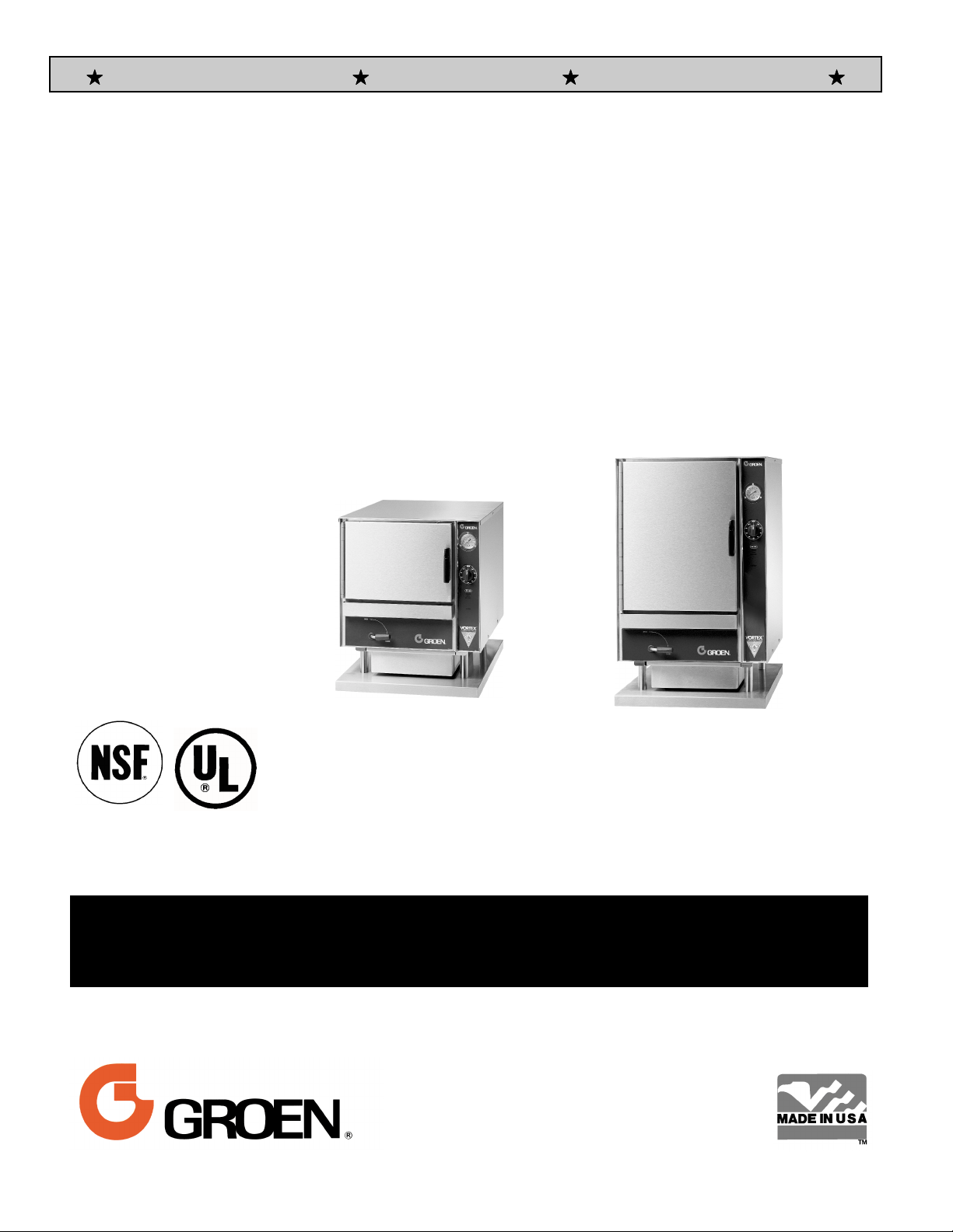
MODELS: VRC-3E, VRC-6E
Vortex™
Atmospheric Connectionless
Steamer
Self-Contained
Electric Heated
Capacity: 3 Steamer Pans [per cavity] (VRC-3E)
6 Steamer Pans [per cavity] (VRC-6E)
THIS MANUAL MUST BE RETAINED FOR FUTURE REFERENCE. READ,
UNDERSTAND AND FOLLOW THE INSTRUCTIONS AND WARNINGS
CONTAINED IN THIS MANUAL.
FOR YOUR SAFETY
DO NOT STORE OR USE GASOLINE OR OTHER FLAMMABLE VAPORS AND
LIQUIDS IN THE VICINITY OF THIS OR ANY OTHER APPLIANCE.
Information contained in this document is
known to be current and accurate at the time
of printing/creation. Unified Brands recommends referencing our product line websites,
unifiedbrands.net, for the most updated
product information and specifications.
Page 2

IMPORTANT — READ FIRST — IMPORTANT
WARNING: WHEN YOU OPEN THE DOOR, STAY AWAY FROM STEAM COMING OUT OF THE UNIT.
STEAM CAN CAUSE BURNS.
WARNING: BEFORE CLEANING THE OUTSIDE OF THE STEAMER, DISCONNECT THE ELECTRIC
POWER SUPPLY. KEEP WATER AND CLEANING SOLUTIONS OUT OF CONTROLS AND
ELECTRICAL COMPONENTS. NEVER HOSE OR STEAM CLEAN ANY PART OF THE UNIT.
WARNING: ALLOW COOKING CHAMBER TO COOL BEFORE CLEANING.
WARNING: DO NOT MOVE THE UNIT WITH WATER IN THE CAVITY OR DRAIN PAN.
WARNING: ALLOW WATER IN DRAIN PAN TO COOL BEFORE EMPTYING.
WARNING: DO NOT PUT HANDS OR TOOLS INTO THE COOKING CHAMBER UNTIL THE FAN HAS
STOPPED TURNING.
WARNING: DO NOT OPERATE THE UNIT UNLESS THE REMOVABLE RIGHT SIDE PANEL HAS BEEN
RETURNED TO ITS PROPER LOCATION.
WARNING: USE OF ANY REPLACEMENT PARTS OTHER THAN THOSE SUPPLIED BY GROEN OR THEIR
AUTHORIZED DISTRIBUTOR VOIDS ALL WARRANTIES AND CAN RESULT IN BODILY
INJURY TO THE OPERATOR AND DAMAGE THE EQUIPMENT. SERVICE BY OTHER THAN
FACTORY-AUTHORIZED PERSONNEL WILL VOID ALL WARRANTIES.
WARNING: HIGH VOLTAGE EXISTS INSIDE CONTROL COMPARTMENTS. DISCONNECT FROM BRANCH
CIRCUIT BEFORE SERVICING. FAILURE TO DO SO CAN RESULT IN SERIOUS INJURY OR
DEATH.
WARNING: DO NOT USE CHEMICALS OTHER THAN MILD DETERGENTS TO CLEAN THE COOKING
CHAMBER
WARNING: CAREFULLY READ THE OPERATION INSTRUCTION LABEL BEFORE OPERATION OF THE
UNIT.
CAUTION: SHIPPING STRAPS ARE UNDER TENSION AND CAN SNAP BACK WHEN CUT.
CAUTION: DO NOT INSTALL UNITS WITHIN 2 INCHES OF A HEAT SOURCE SUCH AS A BRAISING PAN,
DEEP FRYER, CHAR BROILER OR KETTLE.
NOTICE: DO NOT USE ANY DE-GREASER THAT CONTAINS POTASSIUM HYDROXIDE OR SODIUM
HYDROXIDE OR THAT IS ALKALINE.
.
2
Page 3

Table of Contents
OPERATOR WARNINGS ....................................................................2
REFERENCES.............................................................................3
EQUIPMENT DESCRIPTION ................................................................. 4
INSPECTION AND UNPACKING ..............................................................4
INSTALLATION AND START-UP ............................................................ 5-6
OPERATION ............................................................................ 8-9
CLEANING............................................................................... 10
MAINTENANCE...........................................................................11
TROUBLESHOOTING......................................................................11
PARTS LIST............................................................................12-14
WATER FILL DRAIN KIT INSTALLATION INSTRUCTIONS ....................................... .15
WATER FILL DRAIN KIT DIAGRAM ......................................................... .16
RACKS, PAN INSTALLATION INSTRUCTIONS ................................................ .17
WIRING DIAGRAMS .................................................................... 18-19
SERVICE LOG............................................................................20
WARRANTY PROTECTION .............................................................. 21-22
References
UNDERWRITERS LABORATORIES, INC.
333 Pfingsten Road
Northbrook, Illinois 60062
NFPA/70 The National Electrical Code
NATIONAL SANITATION FOUNDATION
3475 Plymouth Road
Ann Arbor, Michigan 48106
NATIONAL FIRE PROTECTION ASSOCIATION
60 Batterymarch Park
Quincy, Massachusetts 02269
Website Address:
www.groen.com
3
Page 4
Equipment Description
Your Groen VRC-3E or VRC-6E Vortex
Connectionless Steamer is designed to give years
of service. It has a stainless steel cavity (cooking
chamber) which is served by an inside water
reservoir which is electrically heated. A powerful
blower circulates the steam in the cavity to increase
heating efficiency.
The cavity holds up to three (VRC-3E) or six (VRC6E) steam table pans (12" x 20" x 2½" deep). An 18
gauge stainless steel case encloses the cavity and
the control compartment that houses electrical
components. Door hinges are reversible (the door
may be set to open from the left or right). Operating
Controls are on the front panel.
VRC-3E and VRC-6E steamers are equipped with
fully electronic controls. These units are readily
identified by their unique control panels. The On-Off
switch is operated by touch pad controls.
From the rear of the VRC-3E and VRC-6E units are
distinguished by the addition of a fuse box, which lets
operators change fuses without removing panels.
The VRC-3E holds three standard 12"x 20"x 2-½"
or two 12"x20"x4" steamer pans.
WARNING
DISCONNECT ELECTRICAL POWER BEFORE
CHANGING FUSES. FAILURE TO DO SO WILL
CAUSE ELECTRICAL SHOCK OR DEATH.
Inspection and Unpacking
The Steamer will be delivered completely assembled
in a heavy shipping carton strapped to a skid. On
receipt, inspect carton carefully for exterior damage.
If damage is evident, notify the local carrier
immediately and file a damage claim. Groen
assumes no liability for damage incurred in transit.
Reconfirm that the voltage at the location is
compatible with the steamer you received.
CAUTION
SHIPPING STRAPS ARE UNDER TENSION AND
CAN SNAP BACK WHEN CUT.
Carefully cut the straps and detach the s ides of the
carton from the s kid. Pull the c arton up off the unit.
Be careful to avoid personal injury or equipment
damage from staples which might be left in the carton
walls.
The VRC-6E holds up to six standard
12"x20"x2-½" or four 12"x20x4" steamer pans.
CAUTION
THE VRC-3E WEIGHS 150 POUNDS (68 KG).
THE VRC-6E WEIGHS 170 POUNDS (77 KG).
YOU SHOULD GET HELP AS NEEDED TO LIFT
THIS WEIGHT SAFELY.
Write down the model number, serial number and
installation date. Keep this information for reference.
Space for these entries is provided at the top of the
Service Log in the back of this manual.
When starting installation, check packing materials
to make sure loose parts such as the drain pan drip
tray are not discarded with this material.
4
Page 5
Installation and Start-Up
CAUTION
DO NOT INSTALL THE UNIT WITHIN 2 INCHES OF A HEAT SOURCE (SUCH AS A BRAISING PAN, DEEP FA T
FRYER, CHARBROILER OR KETTLE).
Electrical Supply Connection - Observe all local, national, or other applicable codes.
Three phase models of the
Steamer are supplied with a cord set ready to be
connected to a power supply. See the chart below
for the correct matching receptacle (not supplied with
the unit).
Single phase models are designed to be directly
connected (hard wired) to the electrical supply and
allow sufficient loop in the flexible conduit to facilitate
inspection, servicing, and cleaning.
FIELD WIRING TABLE - USE COPPER WIRE ONLY - INSULATION RATING (90ºC)
VOLTAGE
(60 Hz Only)
208 3 PHASE 9kw 12kw 25 Amps 34 Amps
240 3 PHASE 9kw 12kw 22 Amps 29 Amps
480 3 PHASE 9kw 12kw 11 Amps 15 Amps
Vortex™ Connectionless
ELECTRICAL SUPPLY CONNECTIONS
KW RATED CURRENT DEMAND
VRC-3E VRC-6E VRC-3E VRC-6E
Branch Circuit Protection
Each Steamer, including individual units of stacked
models, should have its own branch circuit protection
and ground wire. Current and power demands for
each unit are as shown below.
PLUG AND RECEPTACLE CHART
VOLTS PHASE PLUG RECEPTACLE
9kw 12kw 9kw 12kw
208 3 15-30P 15-50P 15-30R 15-50R
240 3 15-30P 15-50P 15-30R 15-50R
480 3 L16-30P L16-30P L16-30R L16-30R
208 1 ---- ---- ---- ---240 1 ---- ---- ---- ----
WARNING
GROUNDING INSTRUCTIONS: THIS APPLIANCE MUST BE CONNECTED TO A GROUNDED
METALLIC, PERMANENT WIRING SYSTEM, OR AN EQUIPMENT GROUNDING
CONDUCTOR MUST BE RUN WITH THE CIRCUIT CONDUCTORS AND CONNECTED TO
THE EQUIPMENT GROUNDING TERMINAL ON THE STATION.
5
Page 6
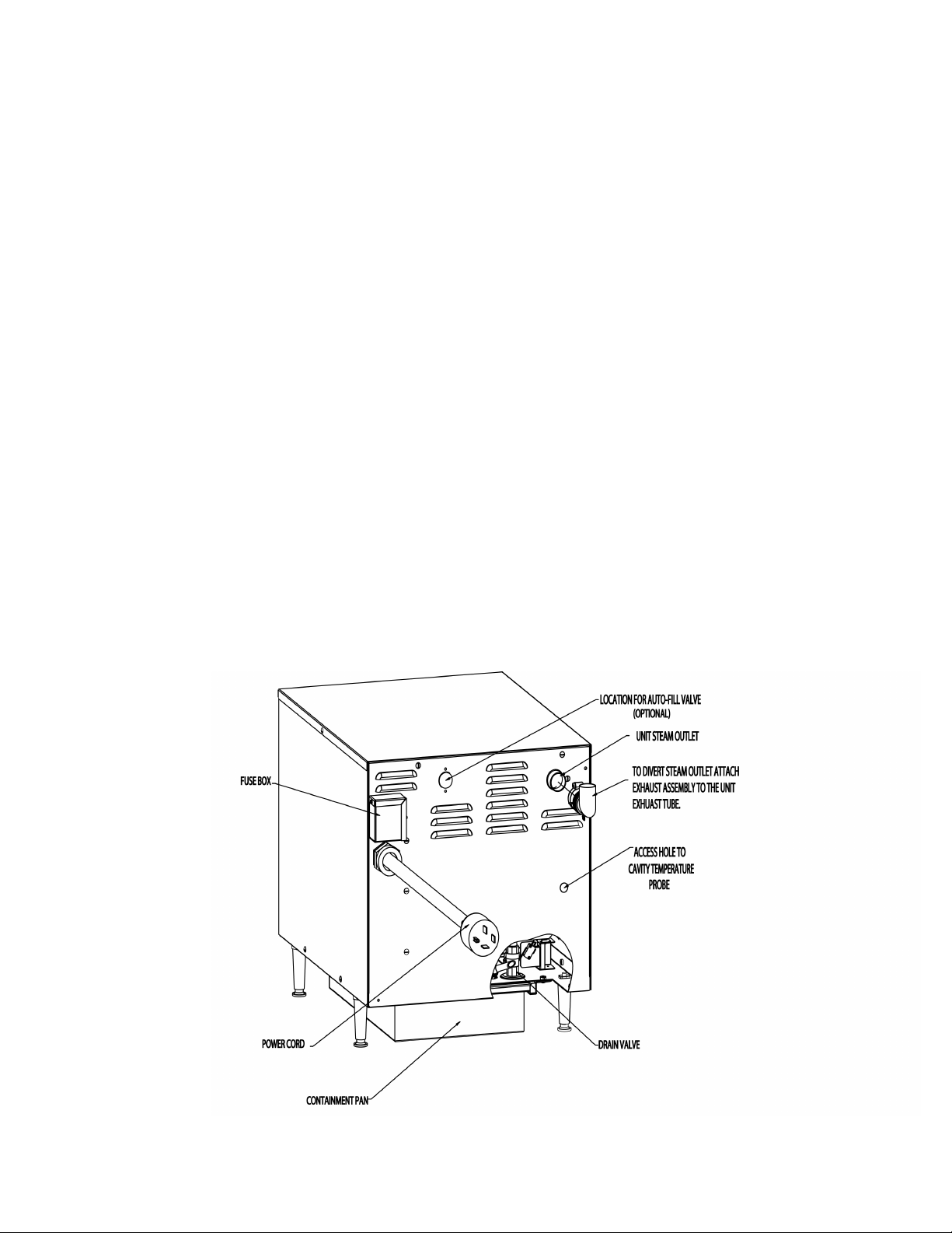
Water Connection(s)
No water connection is needed. The water will be
poured directly into the water cavity reservoir. Avoid
the use of any chemically treated water specifically
filtered water.
Instructions for connecting the optional auto-fill drain
kit are included with the kit.
Drain Connection
The Vortex™ Connectionless Steamer should be
manually drained to the bottom containment pan
supplied by the factory. If the unit is connected to a
drain, do not connect more than two units to one
drain line or pressure from one unit will effect the
second unit.
Stacking Units Instructions
Remove drain containment pan from the bottom of
unit(s). Unscrew to remove adjustable legs from
base of Vortex unit(s). Unfasten nuts and bolts on
stand platform(s). Place Vortex unit(s) on stand
platform. Align the (4) leg holes with the holes in the
platform. Secure Vortex unit(s) to stand platform(s)
using bolts and washers provided in step 2 as shown
in detail “A” of figure 1 on page 7.
For double stack units only:
By loosening the left screw and removing the right
screw provided, mount steam exhaust bracket
assembly to the back panel of the top Vortex unit as
shown in detail “B” of Figure 1 on page 7. Attach the
steam exhaust hose from the bottom Vortex unit’s
steam outlet tube to the top Vortex unit’s steam
exhaust bracket assembly using hose clamps
provided as shown in figure 2 on page 7. (Note:
Steam exhaust hose may need to be cut to fit.)
Steam Vent Assembly Instructions
Remove steam diverter assembly from
literature bag which can be found inside of unit.
Slide loose end as shown over unit steam outlet,
tighten worm gear clamp with flat head screw driver.
Be sure steam outlet is pointing in the upward
position. (Shown below)
6
Page 7
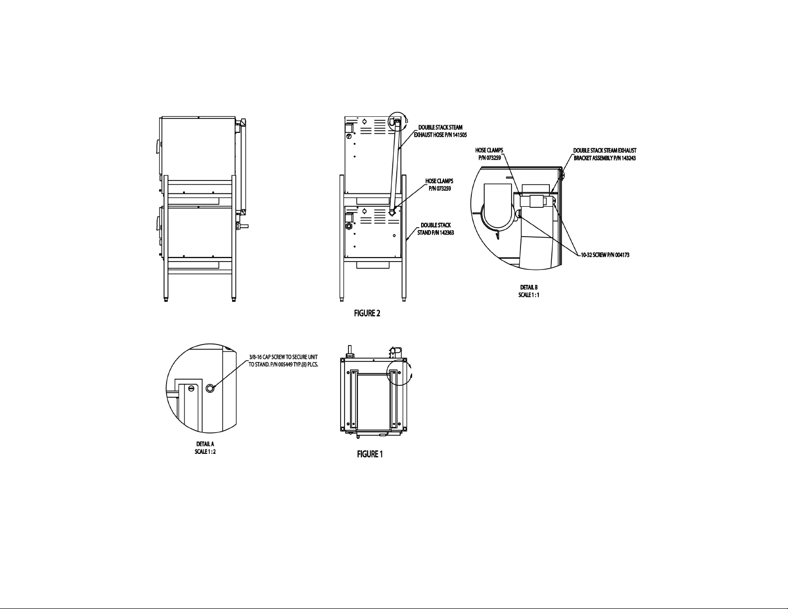
Double Stack Assembly Diagram
7
Page 8

Operation
WARNING
ANY POTENTIAL USER OF THE EQUIPMENT MUST BE TRAINED IN SAFE AND CORRECT OPERATING
PROCEDURES.
A. Controls
! The HI TEMP indicator light comes on
Operator controls are on the front right of the unit.
The VRC-3E and VRC-6E control panels have the
following touch pads and indicator lights:
! The ON/OFF touch pad gets the
Vortex™ ready for use, or shuts it off.
! The HOLD indicator light shows that the
cavity is at holding temperature.
! The TIMING indicator light stays on
when the timer is running.
when the bottom of the water reservoir
becomes too hot.
The unit will automatically shut off, and
cannot be turned on again until the water
reservoir cools down.
! The HI TEMP light will remain
illuminated until the controls are turned
on and the unit temperature is low
enough to restart. Then reset the
manual reset latch as indicated on the
bottom label.
! The ADD H20 indicator light is lit when
it’s time to add water.
! The open and closed position of the
drain valve allows the unit to be filled
with water or drained. This is also used
to manually reset the unit.
Open/Close Handle
! When power has been interrupted to
the Vortex or the HI TEMP light has
come on, the RESET light will illuminate.
The drain handle will need to be
momentarily opened or closed to
extinguish light.
8
Page 9

The timer is used in three ways:
1 In the HOLD position the steam
generator stays at a low boil or “holding”
temperature. Factory set at 180°F.
! If you want to steam continuously, turn the
timer to the manual ON position. The green
ON light will illuminate. The unit will continue
steaming.
2 When a cook time is set, the timing light
will illuminate. The unit steams until the
timer runs down to DONE. At that time
steaming stops, the DONE light
illuminates and a beeper sounds.
3 When the timer is turned to the ON
position, the unit steams continuously.
The green ON light will stay illuminated.
B. Operating Procedure
NOTE: When the unit is first installed, or
anytime incoming power is interrupted, the
RESET light will illuminate. Momentarily turn
the drain handle to open then back to close
to reset the unit and extinguish the RESET
light.
1. With the cooking chamber water reservoir
“empty” press the ON/OFF touch pad. The
ADD H2O light will illuminate when the door
is opened.. Pour water into the reservoir
through the door. When the water level
comes up to the hi probe the reservoir is full
and 3 beeps will sound. Close door.
2. Set the timer knob to the HOLD or ON
position. The unit will be ready in about 20
minutes.
3. Load food into pans in uniform layers. Pans
should be filled to about the same levels,
and should not be mounded.
! If you want to maintain food at holding
temperature turn the timer to the “HOLD”
position.
WARNING
WHEN YOU OPEN THE DOOR, STAY AWAY
FROM THE STEAM COMING OUT OF THE UNIT.
THE STEAM CAN CAUSE BURNS.
6. To remove pans from cavity, open the door.
Remove the pans from the steamer, using
hot pads or oven mitts to protect your hands
from the hot pans.
7. To shut off the unit, press the ON/OFF touch
pad.
8. To drain the remaining water in the water
reservoir, move the drain handle to the
OPEN position. The drain pan will not hold
all of the water in the reservoir. Allow water
to cool before draining. Pull drain pan slowly
from the unit to avoid sloshing.
4. Open the door and slide the pans onto the
supports. If you will only be steaming one
pan, put it in the middle position. Some
foods will cause foam. When cooking foods
that foam, such as shrimp, put an empty
solid 2 ½ “ deep pan in the bottom slot of the
pan racks.
5. Close the door. With the HOLD indicator
illuminated, take one of the following steps:
! If you want to steam the food for a
certain length of time, set the timer for
that period. The timer will automatically
run the steamer for the set time and
then turn it off. A beeper will sound.
Steam production stops. The red DONE
light will illuminate.
WARNING
DO NOT EMPTY UNTIL WATER IS COOL.
EMPTY DRAIN PAN. PA N WILL NOT HOLD ALL
WATER FROM THE RESERVOIR. DO NOT
OVER FILL DRAIN PAN.
9
Page 10

Cleaning
To keep your VRC-3E or VRC-6E Connectionless Steamer in proper working condition, use the following
procedure to clean the unit.
A. Suggested Tools
1. Mild detergent
2. Stainless steel exterior cleaner such as
Zepper®
3. Cloth or sponge
4. Plastic wool or a brush with soft bristles
5. Spray bottle
6. Measuring cup
7. Nylon pad
8. Towels
9. Plastic disposable gloves
B. Procedure
1. Exterior Cleaning
a. Prepare a warm solution of
the mild detergent as
instructed by the supplier.
Wet a cloth with this solution and wring it
out. Use the moist cloth to clean the outside
of the unit. Do not allow freely running liquid
to touch the controls, the control panel, any
electrical part, or on the side or rear panels.
b. To remove material which may be stuck to
the unit, use plastic wool, a fiber brush, or a
plastic or rubber scraper with a detergent
solution.
d. Use a mild detergent to wipe down the steamer
cavity, the probes on the inside back panel wall
and the pan racks.
e. Rinse the unit to remove detergent.
f. Attach pan racks. Unit is ready for use.
WARNING
KEEP WATER AND CLEANING SOLUTIONS OUT
OF CONTROLS AND ELECTRICAL
COMPONENTS. NEVER HOSE OR STEAM
CLEAN ANY PART OF THE UNIT.
EVEN WHEN THE UNIT HAS BEEN SHUT OFF,
DON’T PUT HANDS OR TOOLS INTO THE
COOKING CHAMBER UNTIL THE FAN HAS
STOPPED TURNING.
DON’T OPERATE THE UNIT UNLESS THE
REMOVABLE PARTITION HAS BEEN PUT BACK
IN ITS PROPER LOCATION.
DO NOT USE ANY ACIDIC CLEANSER,
DELIMER/DESCALER OR CHEMICAL PRODUCTS
TO CLEAN THE UNIT.
c. Stainless steel surfaces may be polished
with a recognized stainless steel cleaner
such as Zepper®.
2. Interior Cleaning - Clean the unit daily or as
residue builds upon the bottom of the oven
cavity.
a. Press ON/OFF to turn the steamer off.
Open the door..
b. Drain the water from the unit into the drain
pan and allow the unit to cool before
cleaning. (Note: If the cavity is full of water,
the drain pan will not hold the entire amount
and must be emptied more than once.)
c. After the unit has cooled, remove pan and
pan racks from the cavity.
IMPORTANT
DO NOT USE ANY METAL MATERIAL (SUCH AS
METAL SPONGES) OR METAL IMPLEMENTS
(SUCH AS A SPOON, SCRAPER OR WIRE
BRUSH) THAT MIGHT SCRATCH ANY
STAINLESS STEEL SURFACE. SCRATCHES
MAKE THE SURFACE HARD TO CLEAN AND
PROVIDE PLACES FOR BACTERIA TO GROW.
DO NOT USE STEEL WOOL, WHICH MAY LEAVE
PARTICLES IMBEDDED IN THE SURFACE WHICH
COULD EVENTUALLY CAUSE CORROSION AND
PITTING.
10
Page 11

Maintenance
The VRC-3E and VRC-6E Steamers are designed
for minimum maintenance, and no user adjustments
should be necessary. Certain parts may need
replacement after prolonged use. If there is a need
for service, only authorized Groen representatives
should perform the work.
If steam or condensate is seen leaking from around
the door, take the following steps:
1. Check the door gasket. Replace it if it is cracked
or split.
2. Inspect the cooking chamber exhaust to be sure
it is not blocked.
3. Adjust the door latch pin to allow for changes
that might occur as the gasket ages.
a. Loosen the lock nut at the base of the latch
pin, then turn the latch pin ¼ turn clockwise,
and tighten the lock nut.
b. After adjustment, run the unit to test for
further steam leakage.
c. If there is still leakage, repeat the
adjustment.
d. Continue adjusting the pin clockwise until the
door fits tightly enough to prevent leakage.
Troubleshooting
This Groen Steamer is designed to operate smoothly and efficiently if properly maintained. However, the following
is a list of checks to make in the event of a problem. Wiring diagrams are furnished inside the service panel.
SYMPTOM WHO WHAT TO CHECK
1. No power User a. Check wall circuit breaker.
b. Disconnect power, then check fuses on back of steamer.
c. Call for service technician.
2. Reset light is on User a. Momentarily turn the drain valve to open then back to
closed to reset.
b. Call for service technician.
3. Any unusual operation User a. Press ON/OFF pad to turn steamer off. Press again to turn
steamer on.
b. Call for service technician.
4. No steam User a. Check and add water as required. (For auto fill units turn
unit off and on)
b. Ensure door is closed.
c. Call for service technician.
5. Door pops open User a. Ensure drain and vent are not plugged. No more than two
units should be attached to a single drain line.
b. Check door pin adjustment per above.
c. Call for service technician.
6. HI TEMP Light is ON User a. Wait 30 minutes for the unit to cool down, RESET light
should come on when unit has cooled. Turn unit on.
Momentarily turn drain valve to reset safety circuit.
b. Call for Service Technician.
7. Dial gage will not read
212
User a. This may be normal, altitude and water purity may affect
temperature reading on the gage.
11
Page 12

Parts List
To order parts, contact your authorized Groen Service Agency. Supply the model designation, serial number, part description, part number, quantity, and
when applicable, voltage and phase.
12
Page 13

Parts List
Key Description Part Key Description Part Key Description Part
1 Drain Pan 140452 19 Water Probe 142689 39 Insulation, Heating Element 142357
2 Ball Valve, ½ N.P.T. 140534 20 Motor Assembly 096740 40 Contactor 119811
3 Leg Appliance, 4" High 041121 21 Remote Reading Dial Thermometer 141055 41 Toroid Transformer 119856
4 Bracket, Line Connection Asm. 140457 22 Door Assembly 130858 x Thermostat, 500 Degree Hi Limit 141661
5 Water Level Board 142533 23 Cover, Control Panel 143255 x Grommet, 3/8 Hole, Front Panel 141670
6 Relay 119813 24 Light & Timer PC Board 137233 x Harness, Timer Motor 123120
7 Capacitor 096813 25 Nut, Lock Nylon Insert 6-32 119855 x Harness, Jumper, Ctr Bd to PC Bd 123122
8 Relay, Dbl Pole Dbl Throw 142542 26 Standoff, HEX. —F 6-32 x 3/4 119826 x Harness, Jumper, Voltage Select 123124
9 Transformer 119815 27 Knob, Timer 123100 x Harness, Control Board 125788
10 Cord Set, 30AMP 208/240V (9kw) 142339 28 Timer 60 Hz 90 Min. 141063 x Harness, Ready Switch 119878
10 Cord Set, 50AMP 208/240V (12w) 142345
29 Nut, Timer Mounting 101145 x Harness, Jumper
10 Cord Set, 30AMP 480 142337 30 Standoff, HEX. —F 32 x 1-1/4 119827 x Harness, Hold Temperature 140924
11 Strain Relief - 3 Phase only 142525 31 PC Control Board 140792 x Blower Wheel 096790
12 Transformer, 208/240 121716 32 Nut, Keps 6-32 071289 x Door Gasket 3E 124849
13 Fuse Box Assembly 119848 33 Handle, Shaft 141668 x Door Gasket 6E 140748
14 Fuse 6 Amp 119823 34 Reset Light Assembly 142537 x Reset light bulb 142547
15 Terminal Block 088214 35 Shaft, Drain Valve Actuator 141074 x Seal, Steamer Motor 096868
16 Ground Lug 119829 36 Plate Support, Insulation 142527 x Motor Insulator 094135
17 Contactor 119811 37 Press Sheet, Heating Element 142509 x Cordset, 30 AMP 3 Phase 480V 142337
18 Cavity Probe 070187 38 Holding Bracket, Heating Element 142356 x Cordset, 30 AMP 3 Phase 240V 142339
123125
x - Item not depicted/called out in drawing or photographs
13
Page 14

VORTEX HEATING ELEMENTS REPLACEMENT KITS
FOR 3 PAN MODELS 9KW 208V Part # 143320
FOR 3 PAN MODELS 9KW 240V Part # 143321
FOR 3 PAN MODELS 9KW 480V Part # 143322
FOR 6 PAN MODELS 12KW 208V Part # 143323
FOR 6 PAN MODELS 12KW 240V Part # 143324
FOR 6 PAN MODELS 12KW 480V Part # 143325
14
Page 15

WATER FILL-DRAIN KIT
INSTALLATION INSTRUCTIONS
1-Remove all parts from shipping cartons.
WARNING: DISCONNECT POWER BEFORE
INSTALLING
2-Check-identify all parts as follow.
2.1- Water fill parts.
- 143122 BULKHEAD FITTING....................................................1
- 143123 JAM NUT, 5/8-18..........................................................1
- 142562 TEFLON WASHER.......................................................1
- 142563 ELBOW, 1/8NPT TO 3/8" HOSE BARB, BRASS..........1
- 143148 HOSE AUTO FILL LINE 3/8" ID. X 38" LONG...............1
- 100934 WATER VALVE............................................................1
- 127523 HOSE CLAMPS...........................................................2
- 005764 SCREW TRUSS MACHINE 8-32 THREAD..................2
2.2- Water Drain Parts
- 142549 ELBOW ¾ HOSE BARB 90 DEG.................................1
- 142550 TEE ¾ HOSE BARB....................................................1
- 143246 DRAIN ASSEMBLY, AUTODRAIN...............................1
- 143250 HOSE LONG ¾”ID X 10ft ............................................1
- 143254 HOSE 3/8" ID X 30" LONG ...... . ................... ................1
3- Water fill installation steps.
3.1 Remove left side panel from the unit.
3.2 Mark the hole center on the left side cavity wall, from the
thermometer bulb hole measure 2.5" down and 9.5" from the
rear of cavity as shown in the diagram.
3.2.a Cut out a 3" square of insulation around the hole center
3.3 Drill a 5/8" DIA. hole. Note; make sure to remove all
burrs on both in and out side of the cavity, any burrs will
cause the fitting to leak
3.3.a Install bulkhead fitting and teflon washer from the
inside of the cavity, and thread jam nut from outside to hold
in place and seal, refer to drawing.
3.4 Thread brass elbow into the bulkhead fitting from outside
of the cavity with barb end pointing toward the back of the
unit as shown on the drawing.
3.5 On the back panel of the unit, locate the 1inch diameter
pre drilled hole and pop out the plug.
3.6 Install the water valve from inside of the unit with the
8-32 screws from outside thru the pre drilled holes
3.7 Connect hose auto fill line to the outlet port on the valve
and to the brass elbow on the side of the unit thru the hose
clamps, see drawing. Use the tension hose clamps to
secure on both ends of the hose, one on the valve and the
other on the brass barb. Note, if you are installing the kit in a
3pan capacity unit cut hose to fit.
3.8 Connect the two hose electrical leads to the solenoid
valve. The leads are marked with WV-1 and WV-2.
The
wiring harness has these two leads loose inside th unit.
4- Water drain installation steps.
4.1 The condensate drain line needs to be disconnected
before the left side cabinet panel can be replaced.
4.1.a From the bottom of the unit just right of the drain valve
unscrew the condensate drip bracket.
4.1.b From the inside, loosen the tension clamps and
remove the bracket from the hose and the hose from the
condensate line.
4.1.c Slide the tension clamps off of the hose and use them
on next step.
4.1.d Install one end of the supplied hose 3/8" inside
diameter x 30" long on the condensate line where the
condensate trap to drain hose were installed before, pull the
other end of the hose through the hole where the bracket
was mounted. Reinstall the inside tension clamp.
4.2 Guide the hose loose end thru the uncovered hole to the
outside bottom of the unit as drawing shows.
4.3 Thread the hose drain assembly onto the unit drain
valve, see drawing.
4.4 Connect the 3/8" diameter x 30" long hose loose end to
the plastic barb fitting on the drain assembly and reuse the
other tension hose clamps.
4.4.a If you are installing a kit on a 3 pan model cut this
3/8" x 30" long hose to fit..
4.5 A 10ft piece of hose is supplied with this kit, it can be cut
to length and used with the elbow to help route the hose to
the proper drain location
4.6 For single units cut the long hose to length as needed to
route it to facility drain. Note hose end must have at least a
2" gap from the floor drain, do not use traps.
4.7 For double stack units, a 6.5" long piece of hose can be
cut to join the upper and lower cavities by using the supplied
tee on the bottom unit, the supplied elbow on the top unit
and a piece to connect the two cavities as shown. Permit a
2" air gap from the floor drain. Do not use traps.
5- Test to ensure the final assembly of the drain
line allows the water to flow freely.
Loops or kinks in the hose will cause back pressure which
may cause the door to pop open during draining.
15
Page 16

Water Fill Drain Kit Diagram
16
Page 17

PAN RACKS FOR SINGLE STANDS ONLY
INSTALLATION INSTRUCTIONS
ASSEMBLY INSTRUCTIONS:
1. Unpack racks kit.
2. Identify parts.
3. Unscrew and remove screws #1 and washers #2 from the bottom of your steamer. Do not move the steamer. This will allow the bottom threaded
holes to stay aligned with the holes on the stand.
4. Secure brackets #3 using screws #1 and washers #2 thru the holes on the stands and into the threaded holes on the bottom of your steamer.
5. To place racks on stand, align wires from top of the rack with the corresponding holes in bracket #3. Push the rack all the way up into the bracket.
Align bottom of the rack wires with the holes in the stand leg and allow rack to fall in position.
17
Page 18

Wiring Diagram- VRC-3E
18
141791 Rev E
Page 19

Wiring Diagram- VRC-6E
19
143258 Rev B
Page 20

Service Log
Model No.
Serial No.
Date Purchased
Purchase Order No.
Date Maintenance Performed Performed by
Purchased From
Location
Date Installed
For Service Call
20
Page 21

GROEN® LIMITED WARRANTY TO COMMERCIAL PURCHASE*
(U.S. & Canadian Sales Only)
Groen® warrants to original commercial purchaser/users that foodservice equipment manufactured by Groen® (“Groen® Equipment”) other than
CapKold® foodservice equipment, shall be free from defects in material and workmanship for twelve (12) months from the date of installation or
fifteen (15) months from date of shipment from Groen®, whichever date first occurs (the “Warranty Period”), in accordance with the following terms
and conditions:
I. This warranty is limited to replacement parts and related labor for Groen® Equipment located at its original place of installation in the United
States and Canada.
II. Damage to Groen® Equipment t hat occurs during shipm ent must be reported to the carri er, and is not covered under this warranty. The
reporting of any damage during shipment is the sole responsibility of the commercial purchaser/user of such Groen® Equipment.
III. For Groen® Convection ComboTM Steamer-Ovens, HyPerSteamTM Convection Steamers and HyPlusTM Pressureless Steamers, Groen®
further warrants to the original commercial purchaser/users of such Groen® Equipment that the atmospheric steam generators or boilers contained
in such Groen® Equipment s hall be f ree from def ect s in material and workmanship for t wenty-four (24) m ont hs f rom the dat e of in st allat ion or
twenty-seven (27) months from date of shi pm ent f rom Groen®, whichever date first occ urs, provided that: (a) the origi nal purchas er/us er shal l
have also purchased and installed a Groen® P ureSteem Wa ter T reatment Sys temTM for use in connection with s uch Groen® Convection
ComboTM Steamer-Oven, HyPerSt eamTM Convection Steamer or HyPlusTM Pressureless Steamer on or before the date s uch Groen®
Equipment was installed, (b) the original purchaser/user has continuously used such Water Treatment System in connection with such Groen®
Equipment from the date of installation, and ©) the commercial purchaser/user shall have maintained such Water Treatment System in accordance
with the maintenance and filt er cartridge replacement recommendations of Groen®, and otherwis e maintained such Oven or Steam er in
accordance with all other operational and maintenance recommendations of Groen®.
IV. Groen® further warrants to the original commercial purchaser/users of Groen® Convection ComboTM Steamer-Ovens that the electronic
relay and control board contained in such Groen® Convection ComboTM Steamer-Oven shall be free from defects in material and work manship
for twenty-four (24) months from t he date of inst all ation or t wenty-seven (27) months from date of shipm ent from Groen®, whichever date f irs t
occurs.
V. During the Warranty Period, Groen®, directly or through its authorized service representative, will either repair or replace, at Groen’s sole
election, any Groen® Equipment determined by Groen® to have a defect in material or workmanship. As to any such warranty service during the
Warranty Period, Groen® will be responsible for relat ed reasonable labor and portal to portal transportation expenses (time &
mileage) incurred within the United States and Canada.
VI. This warranty does not cov er boiler m aintenance, calibrat ion, periodic adjust ments as spec ified in operat ing inst ructio ns or manual s,
consumable parts (such as scraper blades, gaskets, packing, etc.), and labor costs incurred for removal of adjacent equipment or objects to gain
access to Groen® Equipm ent. This warranty does not cover defect s caused by im proper install ation, abuse, careless op era tio n, or im proper
maintenance of Groen® Equipment. This warranty does not cover damage to Groen® Equipment caused by poor water quality or improper boiler
maintenance.
VII. THIS WARRANTY IS EXCLUSIVE AND IS IN LIEU OF ALL OTHER WARRANTIES, EXPRESSED OR IMPLIED, INCLUDING ANY
IMPLIED WARRANTY OF MERC HANTABIL ITY OR FITNESS FOR A PARTICUL AR PURPO SE, EACH OF WHICH IS HEREBY EX PRESSL Y
DISCLAIMED. THE REMEDIES DESCRIBED ABOVE ARE EXCLUSIVE AND IN NO EVENT SHALL GROEN® BE LIABLE FOR SPECIAL,
CONSEQUENTIAL, OR INCI DENTAL DAMAGES FOR THE B RE ACH OR DELAY IN PERFORMANCE OF T HIS WARRANTY.
VIII. Groen® Equipment is for commercial us e onl y. If sold as a component of another (O.E.M.) manufac turer’s equipment, or if used as a
consumer product, such Equipment is sold AS IS and without any warranty.
*Covers all Groen® Equipment (other than CapKold® foodservice equipm ent ) ordered after September 11, 2001.
21
Page 22

GROEN® LIMITED EXTENDED WARRANTY COVERAGE*
(U.S. & Canadian Sales Only)
Limited Extended Warranty Coverage is available on al l standard Groen® Equipment (other than CapK ol d® foodservice equipment)
covered by the above Groen® Limited Warranty. Commercial purchasers/users of Groen® Equipment may elect to extend the standard limited
warranty to cover parts, labor and portal to portal transportation costs (time and mileage) for an additional twelve (12) or twenty four (24) month
period, in addition to the time period of the standard limited warranty described above. Limited Extended Warranty Coverage is not available to
extend the supplemental limited warranty for: (a) atmospheric steam generators or boilers contained in Groen® Convection ComboTM SteamerOvens, HyPerSte am T M C on vection S team ers and HyPlus TM Pressureles s St eamers , or (b) elect ronic relay and c ontrol boards c ontained in
Groen® Convection ComboTM Steamer-Ovens.
Five percent (5.0%) of the LIST PRICE of the Groen® Equipment to be covered by the Limited Extended Warranty for each additional
twelve (12) months of limited extended warranty coverage. The five percent (5.0%) of the LIST PRICE charge will be the net invoice amount for
each year of Limited Extended Warranty Coverage purchased.
Cost of Extended Coverage
Conditions of Coverage
(1) Limited Extended Warranty Coverage m ust be purchased at the time the Groen® Equipment to be co vered i s purchased.
(2) All conditions and limitations on the Standard Limited Warranty Coverage apply to the Limited Extended Warranty Coverage. See above
for details of conditi ons and limitations on the Standard Warranty Coverage.
*Covers all Groen® Equipment (other than CapKold® foodservice equipm ent ) ordered after September 11, 2001.
22
Page 23

1055 Mendell Davis Drive
Jackson, MS 39272
Telephone 601 372-3903
Fax 601 373-9587
OM-VRC-3E/VRC-6E
Part Number 141762 Rev A
Revised 12/02
 Loading...