

Page 1
FLIGHT MANUAL G102
The Manual belongs to ASTIR CS
Registration Number: Serial Number:
Manufactured by: Burkhart Grob Flugzeugbau
86874 Tussenhausen - Mattsies
Flugplatz Mindelheim - Mattsies
Telephone: 08268-998-0
e-mail: [email protected]
Germany
Owner:
Published: August 1975
This manual should always be kept on board the glider
Page 2

FLIGHT MANUAL ASTIR CS
List of effective pages
Chapter Page Date Reference
2
Flight Manual
Cover Page
2
3
4
5
6
7
8
9
10
11
12
13
14
15
16
28.11.2005
28.11.2005
28.11.2005
28.11.2005
28.11.2005
28.11.2005
28.11.2005
28.11.2005
28.11.2005
28.11.2005
28.11.2005
28.11.2005
28.11.2005
28.11.2005
28.11.2005
28.11.2005
17
18
19
20
21
22
23
28.11.2005
28.11.2005
28.11.2005
28.11.2005
28.11.2005
28.11.2005
28.11.2005
Rev. 9 28. Nov. 2005
Page 3

FLIGHT MANUAL ASTIR CS
Contents
Contents page
3
List of effective pages........................................................................... 2
Contents................................................................................................ 3
Addenda................................................................................................ 4
Flying Limitations.................................................................................. 5
Record of weight alterations and weighing........................................... 7
Placards to be displayed in the cockpit ................................................ 9
Notes on Flying the Glider.................................................................. 13
Emergency Procedures...................................................................... 16
Minimum equipment ........................................................................... 18
Weight and center of gravity positions ............................................... 18
Measurements.................................................................................... 18
Weights and moments of the control surfaces ................................... 22
Assembly ............................................................................................ 22
Checks to be made after assembly .................................................... 24
Pre-Launch checks............................................................................. 24
Rev. 9 28. Nov. 2005
Page 4
Page 5

FLIGHT MANUAL ASTIR CS
Flying Limitations
Airspeed Limits (I.A.S.) km/h mph kts
Never exceed (VNE) ..............................250 ........... 155 ..........135
in rough air (VB)................................... 250 .......... 155......... 135
Maneuvering (VA) ...............................170 .......... 105 ...........92
On aero tow (VT) .................................... 170............105 ............92
On winch tow (V
Airbrakes ................................................. 250 ............ 155...........135
Gear extended ....................................... 250 ........... 155 ..........135
A.S.I. Colour Code
33 - 92 kts .............................. Green Border - 60-170 km/h
92 - 135 kts ............................ Yellow Border - 170-250 km/h
At 135 kts ..........................................Red Strip - bei 250 km/h
Weights lbs kp
Empty Weight.................................................circa 560..........255
Maximum permitted weight
without water-ballast ...........................................836 ........ 380
with water-ballast ............................................... 990 .........450
Maximum permitted weight
of non-supporting ports
Weak Link on Winch cable
Maximum Load
Cloud Flying and simple Aerobatics
Permitted if water-ballast is not being carried: See pages 12 - 14
) ...................................120 ............. 74.............64
w
...........................................
.......................................................
528
1100
..........
..........
240
500
5
Rev. 9 28. Nov. 2005
Page 6

FLIGHT MANUAL ASTIR CS
Classification Group
Standard Class (German N)
Centre of Gravity positions
Leveling means with a 1000:40 Incidence Board
set up horizontal on the top of
the rear fuselage.
Datum Line (D, L.) Front edge) of wing at root
Serial-No. 1002 – 1437:
Maximum forward position of C. of G. 250 mm behind D. L. (9.84 i n)
Maximum rearward position 425 mm behind D. L. (16.73 in)
Serial–No. 1438 – 1536:
Maximum forward position of C. of G. 310 mm behind D. L. (12,20 in)
Maximum rearward position 480 mm behind D. L. (18,90 in)
Loading Limitations ASTIR CS
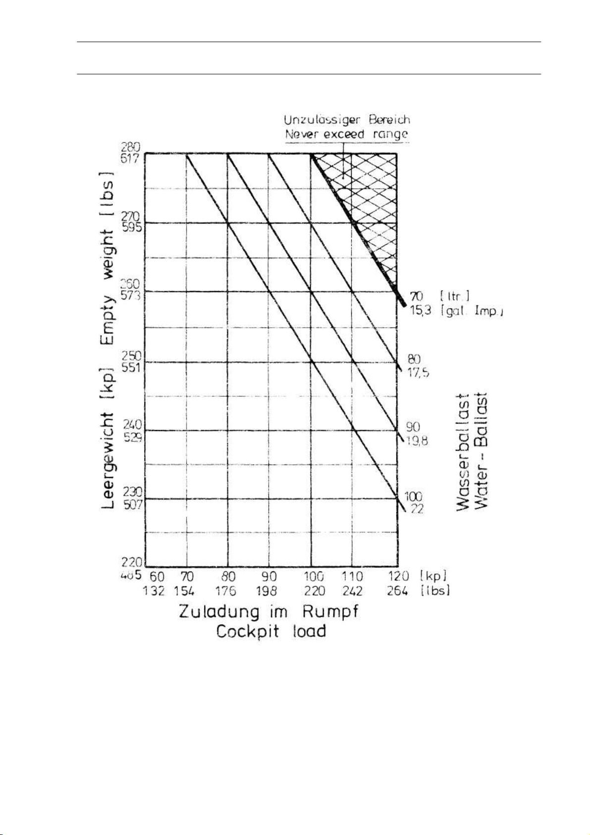
Empty weight of glider and maximum cockpit load, see page 7.
Minimum cockpit load: 154 lbs (70 kp)
The permissible all up weight must NEVER be exceeded.
6
Maximum all up weight
without water-ballast 836 lbs (380 kp)
with water-ballast 990 lbs (450 kp)
The weight of water-ballast is dependent on the cockpit weight (Pilot
with parachute and luggage). See page 7.
Weight deficiencies should be corrected by securing or removing some
ballast in the seat.
The C. of G. of the pilot with a parachute on lies 475 mm in front of
the Datum Line.
Rev. 9 28. Nov. 2005
Page 7
FLIGHT MANUAL ASTIR CS
Record of weight alterations and weighing
ASTIR CS Works Number:
7
Date of weight
alteration:
Weighing by
List of
accessories
(Date):
Empty Weight
(lbs):
Empty Weight
C. of G.
position
behind D.L.
(mm)
Maximum
Cockpit
Weight (lbs)
Rev. 9 28. Nov. 2005
Page 8
FLIGHT MANUAL ASTIR CS
8
Rev. 9 28. Nov. 2005
Page 9

g
A
p
FLIGHT MANUAL ASTIR CS
Placards to be displayed in the cockpit
Maximum weight kp lbs
without water ballast: 380 836
with water ballast: 450 990
Airspeed limits km/h rn.p.h. knots
Never exceed 250 155 135
in rough air 250 155 135
Manoeuvrin
On aero tow 170 105 92
On winch tow 120 74 64
irbrakes 250 155 135
Gear extended 250 155 135
170 105 92
9
Payload (pilot and parachute)
The maximum weight must not be exceeded.
Minimum payload: 70 kp, 154 lbs.
Less weight must be compensated with
ballast in the seat.
Placard to be displayed near undercarriage
Weak links for towing
500 kp, 1100 lbs. max.
Tire: 2,5 bar, 36
si
Rev. 9 28. Nov. 2005
Page 10
FLIGHT MANUAL ASTIR CS
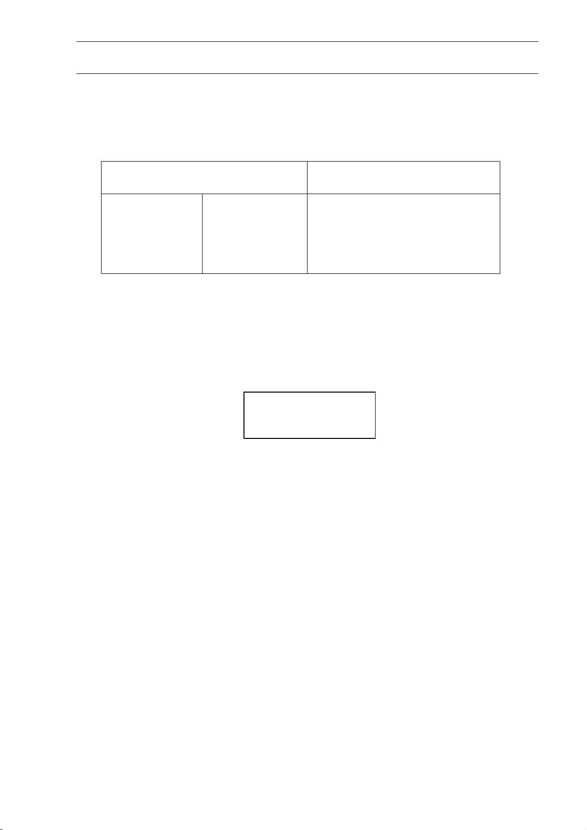
Ballast Weight
Pilot Weight
Incl. Parachute
kg lbs
55 120 6
60 130 4
65 145 2
70 - 100 155 - 220 0
Cover of the container has to be closed tight.
Ballast weight
red
10
Quantity
(Total)
Rev. 9 28. Nov. 2005
Page 11
FLIGHT MANUAL ASTIR CS
11
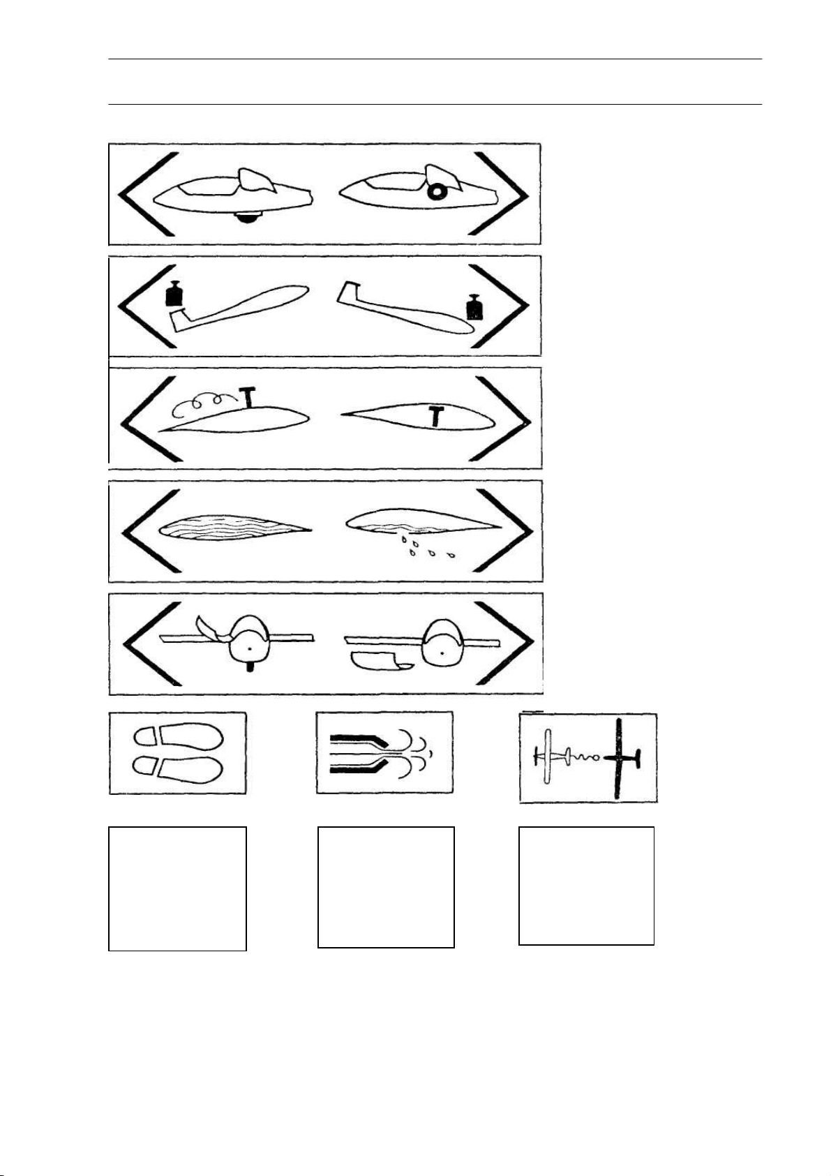
DOWN Under-carriage UP
Handle moves in
Slot on right of
cockpit
Trimmer
On left of cockpit.
GREEN lever
Air-brakes
On the left-hand
Side of the cockpit
BLUE handle
Pedal
Adjustment
Small BLACK
knob
On the top of the
Instrument panel
(right hand)
Air-vent
Small BLACK
knob
On the top of the
instrument panel.
(left hand)
Water-ballast
Jettison
On the right of the
Cockpit.
WHITE lever
Canopy
Round RED knobs.
Left of canopy-frame
OPEN.
Right of canopyFrame JETTISON
Cable Release
In front of the stick
on the left.
YELLOW knob
Rev. 9 28. Nov. 2005
Page 12

FLIGHT MANUAL ASTIR CS
Graph of True v. Indicated Airspeed, showing the effect of Position
Errors.
When the A.S.I. is connected to the following pressure sources:
A.S.I. - Pitot head in tail fin static vents side of the fuselage before the wing root.
12
Rev. 9 28. Nov. 2005
Page 13

FLIGHT MANUAL ASTIR CS
Notes on Flying the Glider
Winch/Auto-tow-Launch
Maximum permitted launch speed: 64 kts
The glider has a belly-hook in the undercarriage well in front of the wheel. A cable
launch presents no difficulties with any C. of G. positions or weight configurations. The
glider has no tendency to balloon and is very stable on the launch. Up to a height of
300ft the nose should be held down if the launch is fast.
Aero tow
Maximum permitted towing speed: 92 kts
The gliders C. of G. position allows the aero tow to be carried out using either the nose
— or belly-hook. During the whole of the time on tow, the glider can be easily controlled
with rudder and aileron, full movements of which can be used if necessary. Even in
strong cross-winds the glider shows no tendency to wander around. At 32 kts the glider
can be lifted off: with 37 — 40 kts indicated, the glider climbs on its own. The
undercarriage can be retracted whilst still on tow. The yellow release knob is positioned
on the left in front of the stick, and should be pulled fully back when releasing the towrope.
Weak Link in tow-cable
Maximum load 1100 lbs
Rudder-pedal Adjustment
To adjust the rudder pedals, push lightly forward on them with the heels and disconnect
the locking device by pulling the handle on the instrument panel. The pedals move
towards the pilot by themselves: to adjust them forward you have to push them against
the pressure of the springs with your heels. The pedals will lock themselves in the
position required when the handle is released.
Canopy
The single-piece perspex canopy has a clear-vision panel and ventilation port, and is
fitted on hinges. The handle for opening it is located on the left-hand side of the canopy
surround: that for jettisoning is on the right-hand fuselage side. To jettison the canopy,
pull both handles back and push it up and away with the left hand.
13
Rev. 9 28. Nov. 2005
Page 14

FLIGHT MANUAL ASTIR CS
Retractable Undercarriage
The undercarriage control lever is located on the right of the cockpit. When retracted or
lowered, the wheel should be locked in place by pushing the control lever in towards
the fuselage side.
Air-brakes
The lever for the air-brakes is situated on the left-hand side of the cockpit. Before
beginning a launch, check that the air-brakes are closed and locked. One should avoid
trying to land with full brake out, since the effectiveness of the brakes means that the
glider is descending fast.
Wheel brake
The lever for the wheel brake is located on the stick.
Trim
The built-in trimmer can be progressively adjusted. The control lever for it is positioned
on the left-hand side of the cockpit behind the airbrake lever. Trim range from 32 kts —
97 kts.
Flight with water-ballast
The glider has the same all up weight as a standard 2 seat glider, when loaded with
water-ballast and a full cockpit load. The slow flight and stalling characteristics of the
fully loaded glider are a little different from one flown without water-ballast. The stalling
speed will be increased to 38 kts. Also larger control movements will be necessary.
The glider will spin cleanly but will recover immediately spin recovery action is taken.
The pilot is advised to have extra height when slow flying or approaching to land while
carrying water-ballast.
Use of Water-ballast
The water-ballast tanks are situated in the front part of the wings, from the root
outwards. Each wing can hold 50 litres. The tanks are filled through an opening in the
top surface of the wing. This is covered by a plug, which can be removed by screwing in
a bolt. The water is drained off through an opening in the underside of the fuselage
behind the wheel-box. To open the valves of the tanks, the control lever on the righthand side of the cockpit should be pulled backwards. It takes about 3 minutes for the
tanks to empty themselves.
14
Rev. 9 28. Nov. 2005
Page 15

FLIGHT MANUAL ASTIR CS
Air from the tanks escapes through the overflow pipe that runs down to a point an the
underside of the wing near the root. When flying with water-ballast the connecting-tape
that covers the gap between fuselage and wings, should be folded back on the
underside in the region of the spar, so that any excess water which may appear runs out
rather than down into the fuselage.
During long flights at an air temperature of 0 ° C (32 ° F) the water-ballast must be
jettisoned because there is danger of collapse of the ballast tanks. When a field landing is
to be made the water-ballast must be jettisoned.
The glider must not be parked over-night with water-ballast on board. If the glider has to
be towed for a long way on the ground with water-ballast on board, the tanks should be
emptied.
When de-rigging the water-ballast tanks will empty themselves through the wing root
connecting pipes.
Stalling Characteristics
Warning of the stall occurs at a speed of 32-35 kts (depending on wing loading), when the
top of the tail unit begins to shudder. If the stick is pulled back even further, the glider
"mushes" but, remains controllable, it being possible to make turns up to an angle of
bank of 20' without the wing dropping away. If the stick is released the glider returns
immediately to the normal flying attitude. If the stick is pulled back quickly, the nose will
drop away but any tendency for a wing to fall can be controlled by the rudder.
Aerobatics
Permitted maneuvers and speeds at which they should be initiated:
Loop..........................................................................................................................92 kts
Chandelle...................................................................................................................92 kts
Steep turn................................................................................................................. 65 kts
Lazy eight ..................................................................................................................65 kts
Spins:
From the fully stalled position, put on full aileron and rudder (crossed). Keep the stick
back. To stop the spin centralize or release one of the controls. Height lost per rotation
is approximately 220 ft. The speed reached when leveling out is about 86 kts.
Maximal positive g loading + 5,3.
Manoeuvres that involve negative g loads are prohibited.
Unorthodox manoeuvres are likewise prohibited
15
Rev. 9 28. Nov. 2005
Page 16

FLIGHT MANUAL ASTIR CS
Spinning
With the Center of Gravity between 415 mm and 480 mm behind the Datum Line, it is
possible to put the glider into a spin from the stalled position. To do so the stick has to
be pulled fully back, and the rudder and aileron controls be fully crossed. The nose will
then drop in the direction in which rudder is being applied, and with a rearward C of G.
position the glider will rotate in a slow, flat spin.
Recovery from the spin can be effected in any way you choose. With almost all C. of G.
positions and wing loadings all that is required is for one of the controls to be released
or returned to its normal position. The quickest recovery (without overstressing the
glider) can be brought about by centralizing all of the controls. The height lost in
returning to the normal flying position after a single-rotation spin, is about 220 ft,
If the glider fails to stop spinning immediately the controls have been centralized, then
the standard method of spin recovery should be employed at once:
1. Full opposite rudder
2. Pause
3. Stick steadily forward
4. When spin stops, centralize controls and resume normal flight
Speed Flying
In speed flying it is quite possible to exceed the maximum permitted speed. At very high
air speeds, care should be taken to use only small control movements so as not to
overstress the glider:
16
Emergency Procedures
Escape Procedure
In the event of a bail out, the following procedure should be followed:
1. Pull both red knobs back on right and left of canopy surround and with left hand
push canopy upwards and backwards.
2. Unbuckle seat harness.
3. EXIT over left or right side
4. Wait only 1 — 3 seconds before pulling the rip cord
Rev. 9 28. Nov. 2005
Page 17

FLIGHT MANUAL ASTIR CS
Flying at High Speed
Within the permitted speed range the glider has no tendency towards high speed flutter.
The controls need only be used at 1/3 of their full movement at 93 kts. The air brakes are
speed limiting and with them open the glider will only reach about 108 kts even in a 45°
dive.
Approach and Landing
The glider can be brought in quite normally at an approach speed of 50 kts. The airbrakes allow a steep approach to be made quite easily. As the action of the brakes makes
the glider slightly nose-heavy, the machine will itself maintain the airspeed it is set at
when the brakes are opened. The sideslip is quite controllable and, if needed, this
manoeuvre can be used to help land the glider.
ATTENTION:
Landing circuit check: Height 500 ft.
Airspeed 50 kts.
WHEEL DOWN AND LOCKED
Flying in rain
A thin layer of water or ice on the wings leads to no deterioration in the flying
characteristics of the glider. With more substantial deposits the stalling speed is
increased by about 3 kts, although the way the glider takes off and touches down
remains the same. Increase the normal flying speed accordingly.
Cloud-flying
The minimum set of Instruments required before cloud flying should be attempted is:
A.S.I., Altimeter, Compass, Turn and Slip Indicator and Radio
The A.S.I. must have the maximum permitted speed marked on it, i. e. red section.
In order to avoid exceeding the maximum permitted speed, the airbrakes should be
opened in good time (i. e. at about 86 kts.)
Warning: Cloud flying and aerobatics should only be carried out by pilots who possess
the appropriate authorization. The statutory regulations must be adhered to.
17
Rev. 9 28. Nov. 2005
Page 18

FLIGHT MANUAL ASTIR CS
Minimum equipment
1. 160kts. A.S.I
2. Altimeter
3.
Vertical speed indicator
4. Four piece safety harness
5. Weighted seat cushion at least 2 3/4", thick, or parachute
6. Loading limitations chart
7. Flying limitations placard
8. Flight manual
18
Weight and center of gravity positions
If new Instruments are added and other changes in the weight of the glider are
made, the empty weight C. of G. position should be checked. If the limits of the
empty weight C. of G. positions and the Loading Limitations Chart are adhered to,
then the C. of G. of the loaded glider will lie within the permitted range.
Serial-No. 1001- 1437 Serial-No. 1438 - 1536
Empty C. of G. position Empty C. of G. position
Weight (lbs) (mm behind Weight (lbs) (mm behind
Datum Line) Datum Line)
506
517
528
539
534 — 682 572 673 — 737
550 577 — 677 583 652 — 732
561 557 — 672 594 631 — 728
572 537 — 667 605 611 — 723
583 518 — 662 616 591 — 719
594 499 — 658 527 573 — 715
605 481 — 654
606 — 693 539 696 — 753
598 — 693 550 688 — 747
591 — 637 561 681 — 742
Measurements
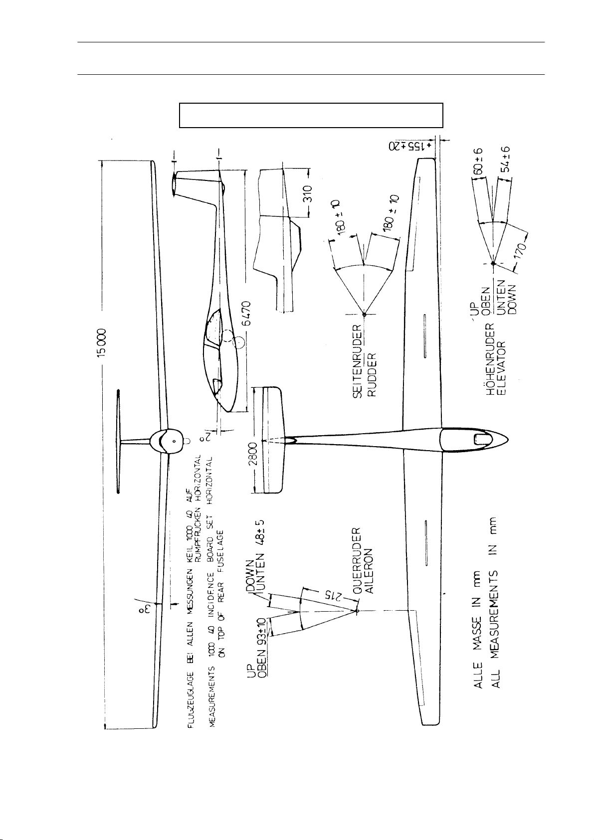
Position of the glider whilst taking all measurements:
with a 1000:40 Incidence Board set up horizontal on the top of the rear fuselage.
Rev. 9 28. Nov. 2005
Page 19
FLIGHT MANUAL ASTIR CS
19
ASTIR CS Serial No. 1438 – 1536
Rev. 9 28. Nov. 2005
Page 20
FLIGHT MANUAL ASTIR CS
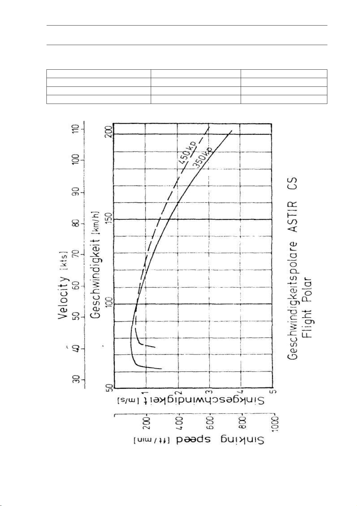
Performance 350 kp 450 kp
Best Glide Angle 37,3 - 95 38 – 105km/h
Minimum Sink (m/sec) 0,6 -75 0,7 – 85 km/h
Circling speed 80 – 85 90 – 95 km/h
20
Rev. 9 28. Nov. 2005
Page 21
FLIGHT MANUAL ASTIR CS
Weights
21
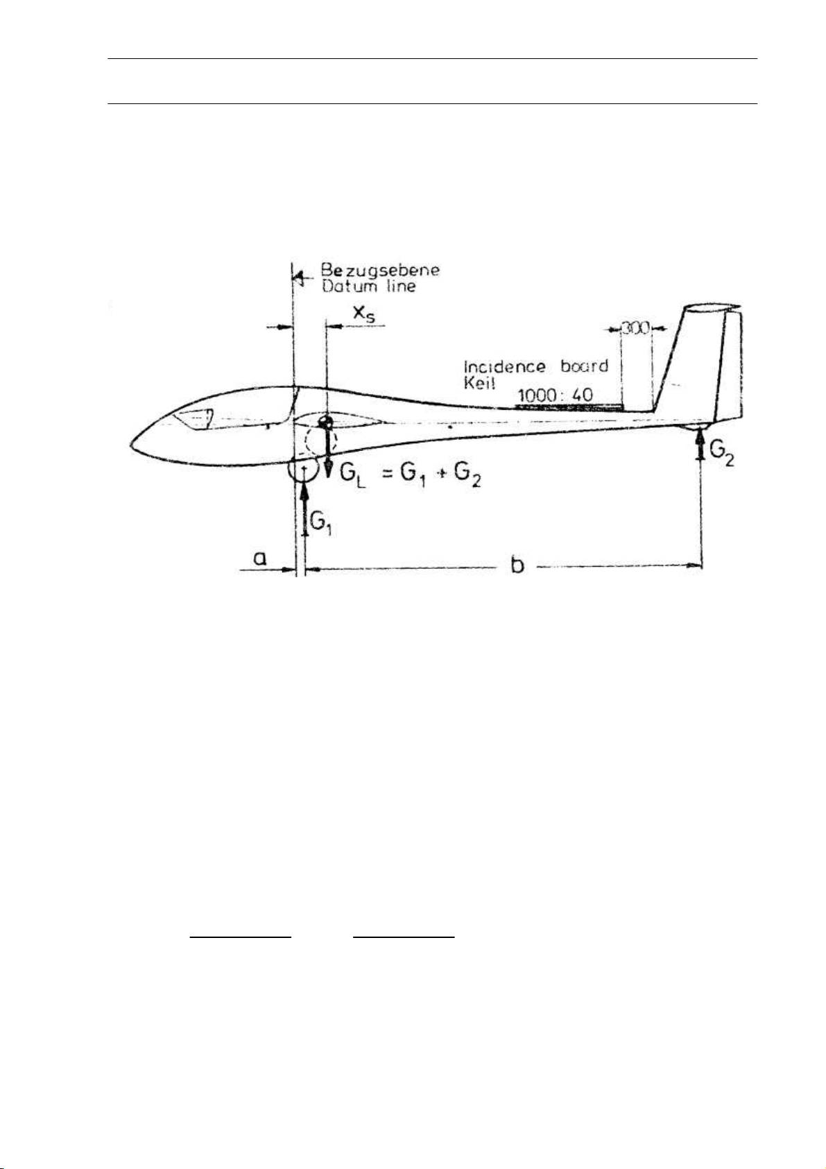
Datum Line: Front edge of the wing at the root.
Leveling means: With a 1000:40 Incidence Board set up horizontal on the top of
the rear fuselage.
Weight on main-wheel G1= lbs
Weight on tail-skid G2= lbs
Empty Weight G
Displacement of main-wheel a = mm
Displacement of tail-skid b = mm
Empty Weight C. of G.
G2 x b
X = + a = + = mm behind Datum Line
GL
Maximum Load G = 836 – GL = lbs
The measurements of determine the empty weight, the empty weight C. of G. and the
loading limitations should always be taken with the glider empty of water ballast
= G1 + G2= lbs
L
Rev. 9 28. Nov. 2005
Page 22

FLIGHT MANUAL ASTIR CS
Weights and moments of the control surfaces
After painting, partial painting or repairs the weights and moments and must not exceed.
Procedure and limits see: Maintenance Manual ASTIR CS and SB 306-34, latest
revision.
Assembly
It is possible to rig the glider with three people.
1. Wings:
Open the 4 main wing fittings in the fuselage. Unlock the air-brakes on the wings. Guide
the right wing into the fuselage. The safety catches on the fuselage sockets will be
released, and on gently moving the wing to and fro will be heard to snap into place.
Next guide the left wing into the fuselage. Move the wing tips up and down so that the
pin on each spar stub is located in the appropriate hole in the opposite wing root. Next the
catches on the left-hand fuselage sockets should be released, and by moving the wing
back-wards and forwards they too can be made to snap into place. To ensure that the
wing-fuselage joint is safely secured, turn the socket catches towards the bayonets
until they drop into place.
Checks
The red circles on the fuselage sides must be covered by the rotated sockets.
2. Aileron and air - brake-connections:
The short connecting rods in the fuselage are fitted with quick-action locks which must
be coupled up to the knobs of the push-rods that move inside the wings.
To fasten the quick action locks, a special tool is provided which guarantees that the knobs
are correctly located in the locks.
After rigging, the connecting rods should be examined to check that pins are properly
inserted, and project some mm out of the locks.
After coupling the quick action locks, check that the ball can not be extracted, by twisting
the lock back and forth. Do this gently with not more than 10 lbs pull. Check all control
connecting rods and locks in a methodical order.
22
Rev. 9 28. Nov. 2005
Page 23
FLIGHT MANUAL ASTIR CS
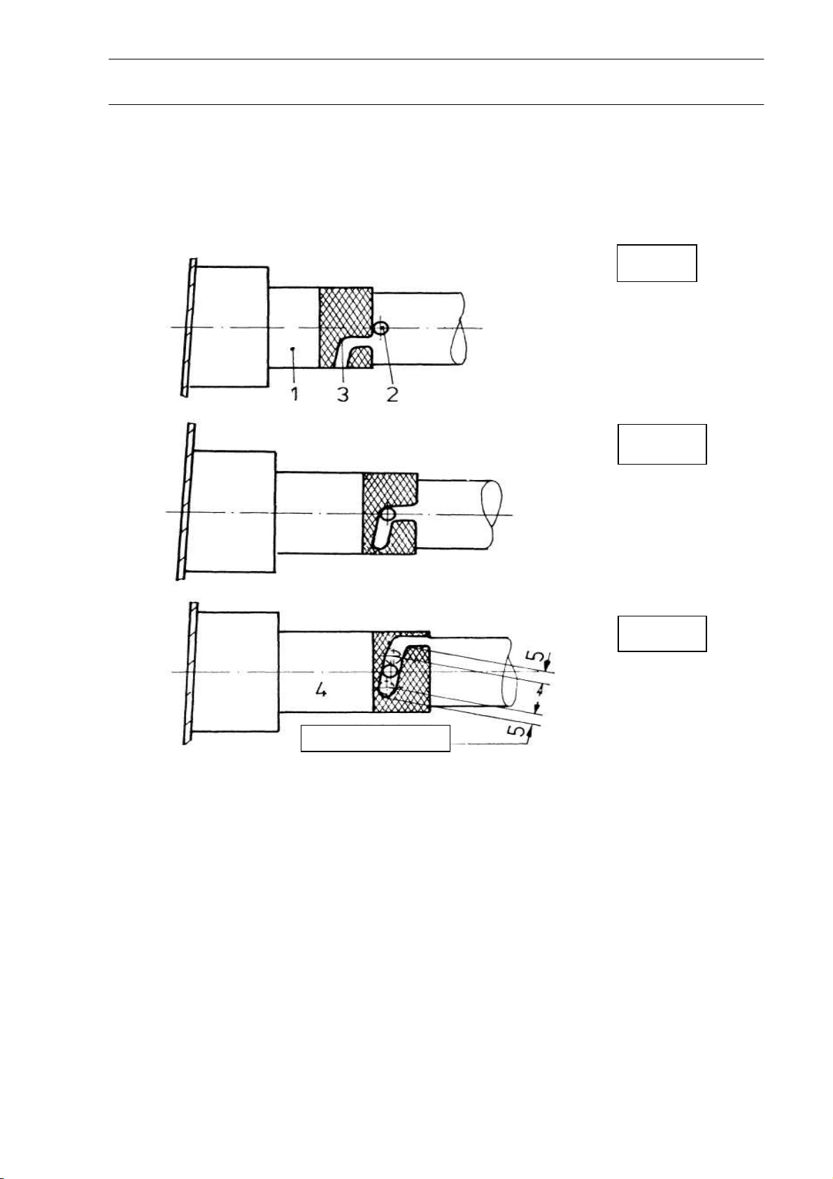
After rigging the following check must be carried out to check the connections are
secure:
open
closed
23
locked
After connecting the quick lock couplings make a visual check that the collar is
extended forward over the bearing far enough for the safety pin to engage.
Rev. 9 28. Nov. 2005
Page 24

FLIGHT MANUAL ASTIR CS
3. Tail plane
The tail plane can be fixed in place by a single person. Stand in front of the fin. Rest
the elevator on the rudder and point the tailplane upwards at an angle of about 45° with
the fin. Next couple the elevator push-road to the knob on the elevator by means of the
quick-action lock. Now drop the tailplane down so that the two retaining pins on the
fuselage disappear up into the cavity in the tailplane. One can now let go of the
tailplane.
To continue with the rigging push the front of the tailplane down. This will activate the
locking bolt and cause the metal pin that projects out of the front of the fin to move
down its slot. When the front of the tailplane has reached its lowest position against the
pressure of the locking mechanism, push the whole unit back with both and into the two
fuselage bolts. The unit is then locked in place when the metal pin in the front of the fin
springs upwards and covers the long narrow slot.
24
Checks to be made after assembly
1 Check that the 4 main wing fittings are locked.
2 Check that aileron and brake quick-action locks are properly located on the knobs.
3 Ensure that the tow hook is functioning correctly.
4 Test the operation of the wheel brake and the pressure of the air in the tire.
5 Check that the tailplane is securely seated and that the elevator push-rod is
connected.
8 Rudder movement.
Pre-Launch checks
1 Do all the controls move freely?
2 Are the air-brakes locked?
3 Is the undercarriage control lever in the most forward position and is it pushed in
flush with the fuselage-wall?
4 Is the trimmer set at neutral?
5 Is the canopy locked?
6 Are the parachute and seat straps drawn in tight and secured?
7 Is the altimeter set to ZERO or the height of the airfield?
8 Is the radio turned on and set to the frequency being used by the airfield control?
Rev. 9 28. Nov. 2005
Page 25

FLIGHT MANUAL ASTIR CS
Inspection of the airbrake locking lever
At the daily check the right and left hand airbrake locking levers have to be checked
through the inspection openings in the wing underside. The lever are made of aluminum
casting and have a facilitating hole. The following instruction has to be carried out:
Inspection of the airbrake locking levers for cracks in one of the 3 legs. For a better
inspection the Plexiglas pane can be removed for easier access. The use of a
magnifying glass is recommended.
If cracks are found, the exchange of the locking levers left and right hand No. 1024123/4124 of aluminum casting for such of aluminum sheet (see TM 306-26) is required.
If the aluminum sheet's are installed, the daily check is not longer applicable.
25
Rev. 9 28. Nov. 2005
Page 26
MAINTENANCE MANUAL G102
The Manual belongs to ASTIR CS
Registration Number: Serial Number:
Manufactured by: Burkhart Grob Flugzeugbau
86874 Tussenhausen - Mattsies
Flugplatz Mindelheim - Mattsies
Telephone: 08268-998-0
e-mail: [email protected]
Germany
Owner:
Published: August 1975
Page 27
MAINTENANCE MANUAL ASTIR CS
List of effective pages
Chapter Page Date Reference
2
Maintenance
Manual
Cover Page
2
3
4
5
6
7
8
9
10
28.11.2005
28.11.2005
28.11.2005
28.11.2005
28.11.2005
28.11.2005
28.11.2005
28.11.2005
28.11.2005
28.11.2005
MSB 306-38/1
Rev. 9 28. Nov. 2005
Page 28

MAINTENANCE MANUAL ASTIR CS
Contents
Contents page
List of effective pages..........................................................................................2
Contents ..............................................................................................................3
Addenda ..............................................................................................................4
Maintenance ........................................................................................................5
Annual Inspection................................................................................................7
Life limited parts...................................................................................................8
3
Weights and moments of the control surfaces ...................................................9
Inspection Procedures for Increase of Service Time........................................10
Rev. 9 28. Nov. 2005
Page 29
Page 30

MAINTENANCE MANUAL ASTIR CS
Maintenance
The greatest care should be taken in maintaining the fiber glass surface of the glider.
Luke warm water should be used to wash off dust, grease, dead flies and other dirty
marks. More resistant dirt should be removed by using a mild cleaning agent. Only
special silicon-free preparations should be used in maintaining the painted surfaces.
Cracks should be carefully filled.
Although very resistant against moisture, the glider should be protected as much as
possible against rain and dampness. Water that has penetrated, should be dealt with
by storing the glider in a dry place, frequently turning over the dismantled parts.
The most effective way to clean the canopy is to use a special perspex cleaner, but if
necessary, lukewarm water can be used. A soft, clean cloth or chamois-leather should
be employed to wipe the canopy down. Never rub perspex with anything dry.
The safety harness should be regularly checked for mildew and general wear and tear.
The metal parts of the harness should be frequently checked for rust.
Because of its position in the wheel cavity the tow-hook is susceptible to contamination
from dirt. Therefore it must be inspected frequently for damage, also regularly clean and
b grease. When the seat-well is removed the hook can easily be taken out. Remove the
connecting wire from the lever and take out two retaining screws. For reconditioning the
tow hook should be sent with the record card to the tow hook manufacturer, Tost.
The main wheel tire pressure should be kept at 2,5 atmospheres (36 psi).
A tail wheel can also be installed instead of the skid
The wheel brake is of the drum type. If required the point at which the brake begins to
drag can be adjusted. The adjustment is carried out by moving the Bowden cable at the
drum end.
When the main wheel is removed for the purpose of cleaning, greasing or changing
the tire, the Bowden cable should be disconnected from the brake-lever. Screw the M 6
threaded special tool onto one side of the axle and take out the screws and the spindle.
Remove the screws that hold the brake-lever in place. Take the wheel out by pulling it
downwards. Clean all the parts and grease before re-assembly.
Before assembling the glider the pins and sockets at the joints between wings and
fuselage, and tailplane and fuselage, should be cleaned and greased.
If repairs are carried out on the glider which are more extensive than normal
maintenance work, the manufacturers should be contacted.
5
Rev. 9 28. Nov. 2005
Page 31

MAINTENANCE MANUAL ASTIR CS
It is absolutely essential to ensure that if the glider is re-painted all surfaces which
are directly exposed to the sun should be painted WHITE.
When any repairs are done or a fresh coat of paint added the position of the
empty weight C. of G. must be re-checked.
Maintenance on Hotellier quick-locks must be conducted during each annual
inspection or 500 hours which ever occurs first. They are installed at the controlconnections of aileron and airbrakes at the wing-fuselage joint and at the elevator
connection to the pushrod.
The diameter of the swivel has to be measured at different points by a
micrometer with no differences in excess of 0,1 mm (0,004 in.) that means the
swivel must still be spherical. If there are large differences the swivels and
appropriate joints must be replaced.
Swivels and joints should be greased prior to each rigging.
The use of additional safety-pins guided through the holes of the wedge-type slides
increases safety, (Safety-pins No. 500 307.71 from A. Wurth, Industrieservice, D –
90431 Nuernberg, Germany or from GROB- Werke)
6
Rev. 9 28. Nov. 2005
Page 32
MAINTENANCE MANUAL ASTIR CS
Annual Inspection
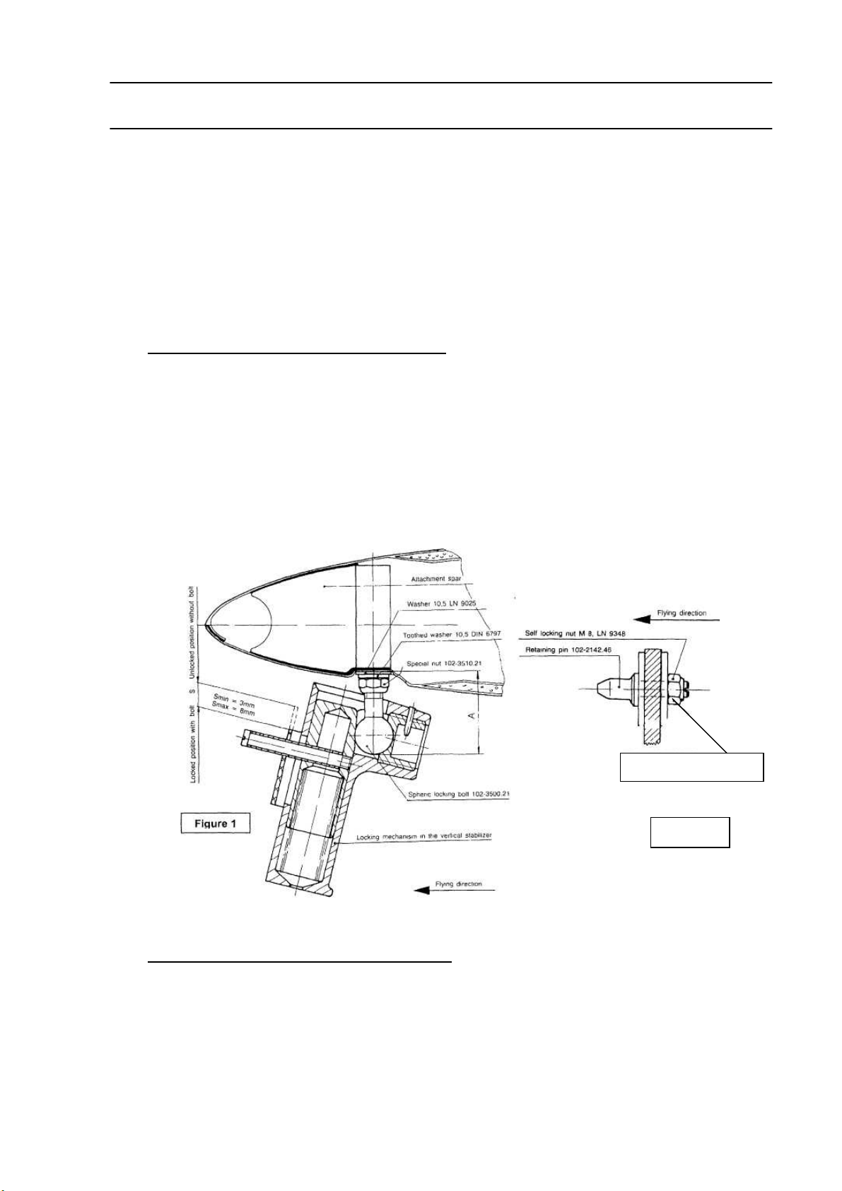
During each annual inspection check front and rear attachment for noticeable play
before de-rigging the horizontal stabilizer. Therefore move the stabilizer at the tips
carefully to all directions.
• If play is noticed in the front attachment the spherical bolt must be replaced (see
figure 1). Determine the ball diameter. When ordering advise the measured diameter
"D" + 0.1 mm. Also advise gap width “S” as measured.
• Remove spherical bolt from elevator. Check bolt for cracks.
• Upon re-installation apply correct torque. (20 Nm, tolerance +4 / -2). (NOTE: See
also MSB 306-38).
7
Torque with 13 Nm
Figure 2
• if play is noticed in the rear attachment the retaining pins 102-2142.46 must be
replaced as follows: (refer to figure 2):
• remove horizontal stabilizer.
• loosen nut M8, hold bolt using a screwdriver.
• during removal of the bolts pay attention that the large washers remain on the
aluminum plate.
Rev. 9 28. Nov. 2005
Page 33

MAINTENANCE MANUAL ASTIR CS
• install new spherical bolts and pay attention that they are properly positioned
in the large washers.
• tighten nut using a torque wrench with 13Nm.
• install horizontal stabilizer and connect control rods.
In case play is still noticeable after replacement of the bolts, the bearings in the
stabilizer spar web must be replaced. This replacement must be done only by an
approved aviation workshop.
Corresponding instructions may be ordered from GROB.
8
Life limited parts
Mandatory Service Bulletin MSB 306-38 introduced the annual inspection and – if
required – the exchange of the spherical bolt 102-3500.21.
Mandatory Service Bulletin MSB 306-38/1 require all spherical bolts 102-3500.21 and
collar bolts 102-2142.46 be exchanged not later than June 30th 2006, unless already
exchanged within the scope of MSB 306-38. Additionally every 10 years / 1000
landings, whichever comes first, spherical bolt 102-3500.21 and collar bolts 102-
2142.46 need to be replaced with new bolts.
The change is to be documented in the aircraft history record and life-limited-parts list.
Rev. 9 28. Nov. 2005
Page 34
MAINTENANCE MANUAL ASTIR CS
Weights and moments of the control surfaces
The weights and the moments of the control surfaces must not exceed the following
values:
ASTIR CS (Serial No. 1002 - 1536)
Elevator .................................... 10,00 – 15,00 kgcm ...................... 2,40 – 3,25 kg
Rudder...................................... 13,65 kgcm ± 10% ........................ 3,20 kg ± 10%
Aileron ...................................... 16,00 kgcm ± 12% ........................ 4,10 kg ± 12%
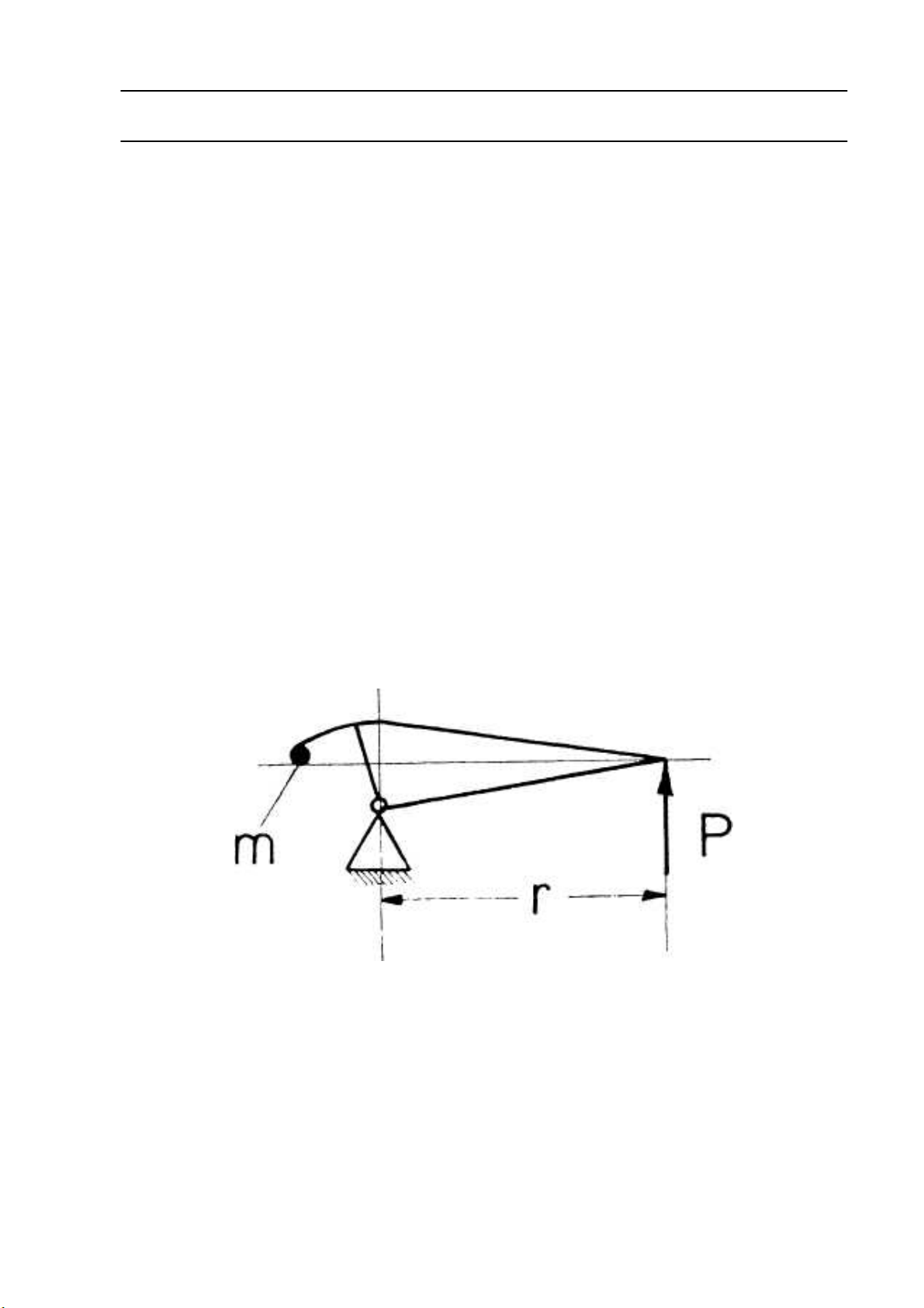
The moments must be measured with the control surfaces removed. To determine the
moment M = P x r the surface should be mounted at the hinge line with the minimum
friction possible. The force P can be measured, for example, using a letter scale. If
these values are exceeded the mass balance should be increased. Before carrying out
repairs which for example involve charging the mass balance on a surface the
manufacturer or his repair agent should be consulted.
9
Rev. 9 28. Nov. 2005
Page 35

MAINTENANCE MANUAL ASTIR CS
Inspection Procedures for Increase of Service Time
1. General
The results of fatigue tests of wing spar sections have demonstrated recently that the
service time of GRP gliders and motor gliders may be extended to 6000 hours, if for
each individual glider (in addition to the obligatory annual inspections) the airworthiness
is demonstrated according to a special multi-step inspection program particularly with
regard to the service life.
2. Time limits
When the glider has reached a service time of 3000 hours, an inspection must be done
in accordance with the inspection program mentioned under point 3. If the results of
this inspection are positive or if any defects found have been duly repaired, the service
time of the glider is extended by another 3000 hours to a total of 6000 hours (first
step).
The above inspection program must be repeated when the glider has reached a service
time of 6000 hours. If the results of this inspection are positive or if any defects found
have been duly repaired, the service time of the glider is extended to 7000 hours
(second step).
When the glider has reached a service time of 7000 hours, the above inspection
program again must be repeated. If the results of the inspection are still positive or if any
defects found have been duly repaired, the service time may be extended to a total of
8000 hours (third step).
The gradual extension of service life will be performed by steps of 1000 flight hours up
to maximum 12 000 flight hours at this time (4th – 7th stage).
Additionally at 9500, 10500, 11500 operating hours, inspection of the wing connection
bolts and main spars spigots must be performed accordance to Service Bulletin TM
306-30, latest edition, action 7.
3. Inspection Program
In each case the latest issue of the inspection program which will be updated
according to incoming inspection results, has to be ordered from the manufacturer.
10
Rev. 9 28. Nov. 2005
Page 36

MAINTENANCE MANUAL ASTIR CS
4. Inspections
The inspection must only be done by the manufacturer or by a licensed repair station
or inspector.
5. Inspection results
The results of the inspections have to be recorded in an inspection test report wherein
comments are required for each inspection instruction. If the inspections are done
outside the manufacturer's facilities, a copy of the records must be sent to the
manufacturer for his evaluation and information
6. Annual Inspection
The annual inspection is not affected by this inspection program.
11
Rev. 9 28. Nov. 2005
Page 37
REPAIR INSTRUCTION G102
The Manual belongs to ASTIR CS
Registration Number: Serial Number:
Manufactured by: Burkhart Grob Flugzeugbau
86874 Tussenhausen - Mattsies
Flugplatz Mindelheim - Mattsies
Telephone: 08268-998-0
e-mail: [email protected]
Germany
Owner:
Published: August 1975
Page 38
REPAIR INSTRUCTION ASTIR CS
List of effective Pages
Chapter Page Date Reference
2
Instruction
Repair
Cover Page
2
3
4
5
6
7
8
9
10
11
12
28.11.2005
28.11.2005
28.11.2005
28.11.2005
28.11.2005
28.11.2005
28.11.2005
28.11.2005
28.11.2005
28.11.2005
28.11.2005
28.11.2005
Rev. 9 28. Nov. 2005
Page 39

REPAIR INSTRUCTION ASTIR CS
Contents
Contents page
List of effective Pages ................................................................................. 2
Contents ...................................................................................................... 3
Foreword ..................................................................................................... 3
Authorized materials and suppliers ............................................................. 4
Simplified texture plan of Astir CS ............................................................... 6
Repair of GRP material ............................................................................... 7
3
Repair of GRP Foam-Sandwich .................................................................. 7
Repair of styrene-foam supported parts ...................................................... 9
Repair of GRP laminate parts...................................................................... 9
Paint-Work................................................................................................... 9
Repair of Metal Fittings ............................................................................ 11
Major Repairs ........................................................................................... 11
Construction details of additional equipment attachment fittings............... 12
Foreword
The glider ASTIR CS is constructed from glass fibre reinforced plastic (GRP).
The fuselage and control surfaces consist of GRP laminate. The load bearing
surfaces (wings) and the tail plane consist of GRP laminate with a foam supporting
layer (GRP foam-sandwich). The tail-fin consists of GRP styrofoam sandwich.
Rev. 9 28. Nov. 2005
Page 40
REPAIR INSTRUCTION ASTIR CS
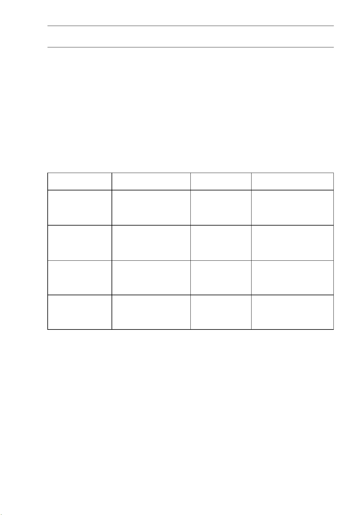
Authorized materials and suppliers
Resin: Shell Epikote 162
Hardener: BASF Laromin C 260
Mixing ratio: 100 parts resin - 38 parts hardener, parts by weight
Glass Fibre Cloth: Supplier: Interglas Textils GmbH. Söflinger Str. 246, 7900 Ulm
Use Cloth Weight g/qm Interglas-No.
4
Double Twill
Fuselage
Wings
Elevator
and
Rudder
Ailerons
All glass-fibre cloth is Alcholine free. E Class with Volan-A-Finish or Finish I 550.
Glass fibre cloth and resin/hardener may be ordered from:
GROB-WERKE, Burkhart Grob e.K. Unternehmensbereich Luft- und Raumfahrt,
86874 Mattsies, Flugplatz Mindelheim-Mattsies, Germany.
Double Twill
Chain Reinforced
Double Twill
Double Twill
Chain Reinforced
Double Twill 276 92 125
Double Twill
Double Twill
161
390
433
161
276
433
276
161
92 110
92 140
92 146
92 110
92 125
92 146
92 125
92 110
Rev. 9 28. Nov. 2005
Page 41

REPAIR INSTRUCTION ASTIR CS
Supplier:
Rovings:
EC 10-80-2400 K 43 Gevetex
4000 Düsseldorf
Postfach 1205
Foam Material:
PVC-Hartschaum Continental AG
Conticell 60, 6 and 8 mm thick 3000 Hannover
Spec. Weight 60 kg/m2
Styrofoam:
Thermopete Poron-Werke GmbH
4 mm thick 6122 Erbach
Spec Weight 15 kg/m
Filling Material for Resin:
Microballoons Brown Lackfabrik Bader KG
Cotton Flock Schwarzwälder Textil-Werke
Type FL 1 f 7623 Schenkenzell
Paint:
PE-Schwabbellack Lesonal-Werke
White. No. 3-69120 7000 Stuttgart 30
PE-Hardener No. 07-20500 Postfach 30 07 09
100 Schwabbellack Paint (Gel-Coat)
10 Hardener mix ratio by Weight.
Thinners No. 6-10170
Red Paint
Nitro-Cellulose-Kombilack Lackfabrik Bader KG
Blood-Orange RAL 2002 7300 EssIingen
Schließfach 25
Manufacturer and supplier data may not represent the latest status.
3
Brunnenstrasse 5
7300 Esslingen
Schließfach 25
Postfach 12
5
Rev. 9 28. Nov. 2005
Page 42
REPAIR INSTRUCTION ASTIR CS
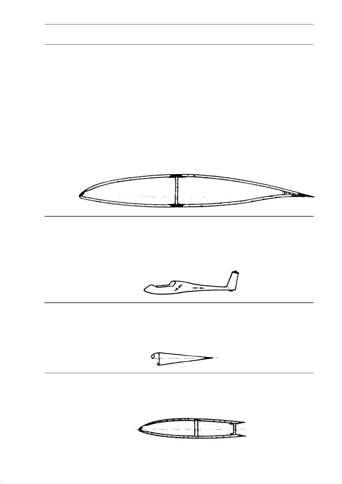
Simplified texture plan of Astir CS
Reinforced regions for special loads and stress conducting are not shown.
1. Flügel
Außenlaminat
1 Lage 92110 diagonal
1 Lage 92125 diagonal
Kern
Conticell 60 8 mm
Innenlaminat
1 Lage 92125
2. Rumpf
Von außen nach innen
1 Lage 92110 längs
1 Lage 92146 längs
3 Lagen 92140 diagonal
3. Ruder
Höhenruder
Seitenruder
Querruder
2 Lagen 92125 diagonal
4. Höhenflosse
2 Lagen 92110 diagonal
Kern: Conticell 60, 6 mm
1 Lage 92110 diagonal
Wlng
Outer laminate
1 Layer 92110
1 Layer 92125
Core
Conticell 60 8 mm
Inner laminate
1 Layer 92125
Fuselage
From outside to inside
1 Layer 92110 lengthwise
1 Layer 92146 lengthwise
3 Layers 92140 diagonally
Controls
Elevator
Rudder
Aileron
2 Layers 92125 diagonally
Fin
2 Layers 92110 diagonal
Core: Conticell 60, 6 mm
1 Layer 92110 diagonally
6
Rev. 9 28. Nov. 2005
Page 43

REPAIR INSTRUCTION ASTIR CS
Repair of GRP material
If the glider is damaged, first examine the outer surface very carefully, frequently other
structural parts are involved, fractures can run hidden under the outer surface. Carry out
repairs with extreme care.
On gliders made of GRP, the outer surface is stressed (load bearing), failure of this
element may lead to structural failure.
Maintain a precise resin-hardener mixing ratio i.e. +/- 0.5% using a clean mixing pot.
The ratio of fibre glass cloth — to resin mix is approximately 1 to 1. Grind or splice the
repair location only shortly before applying damp laminate, so that dirt cannot
contaminate and prevent safe adhesion. As in plywood, the alignment of the fibre glass
cloth (lengthwise or diagonally) is of extreme importance to the strength. The required
amount of fibre cloth and direction in the damaged area may be taken from the
simplified texture plan, so that the damaged area can be restored to the correct wall
strength. If a small piece of the damaged laminate is broken off and burnt, the remaining
glass-fibres can be counted and identified.
Splicing and grinding are time consuming. Grind away as much as necessary so that
the added patches do not protrude from the contour. If it is necessary to shorten the
repair time it may be done with a hot air blower to speed the resin curing time.
Warning. A temperature too high will produce large air bubbles in the cloth / resin. An
improvised warming chamber may be built out of foil, through which hot air can be
guided to avoid local overheating.
Caution must be exercised when repairing control surfaces, be careful not to increase
the weight since this may cause flutter of the respective control surface.
7
Repair of GRP Foam-Sandwich
(GRP Hard Foam-Sandwich)
Damage may happen to the outer surface only (outside laminate) as well as the whole
skin (outside and inside hard foam laminate).
a) Superficial damage
With a split or fracture, the laminate may detach from the supporting foam. Start by
removing loose laminate until firm laminate is reached. To remove the foam laminate use
a grinding disk, grinding block or sharp knife. With a grinding block or sharp knife only
remove the cloth around the damage. Splice ratio per cloth covering approximately 20
mm ratio laminate thickness to splice: approximately 1:50.
Rev. 9 28. Nov. 2005
Page 44

REPAIR INSTRUCTION ASTIR CS
After grinding out the splice, the repair must be thoroughly cleaned. Remove the dirt (also
out of the foam pores) with air pressure. Wash the splice with carbon tetrachloride or
acetone, in case it has been contaminated with dirt or grease.
Fill up the pores of the foam with resin and micro balloons until it is smooth. Then join
the laminates with the correct cloth, aligning it in the right direction.
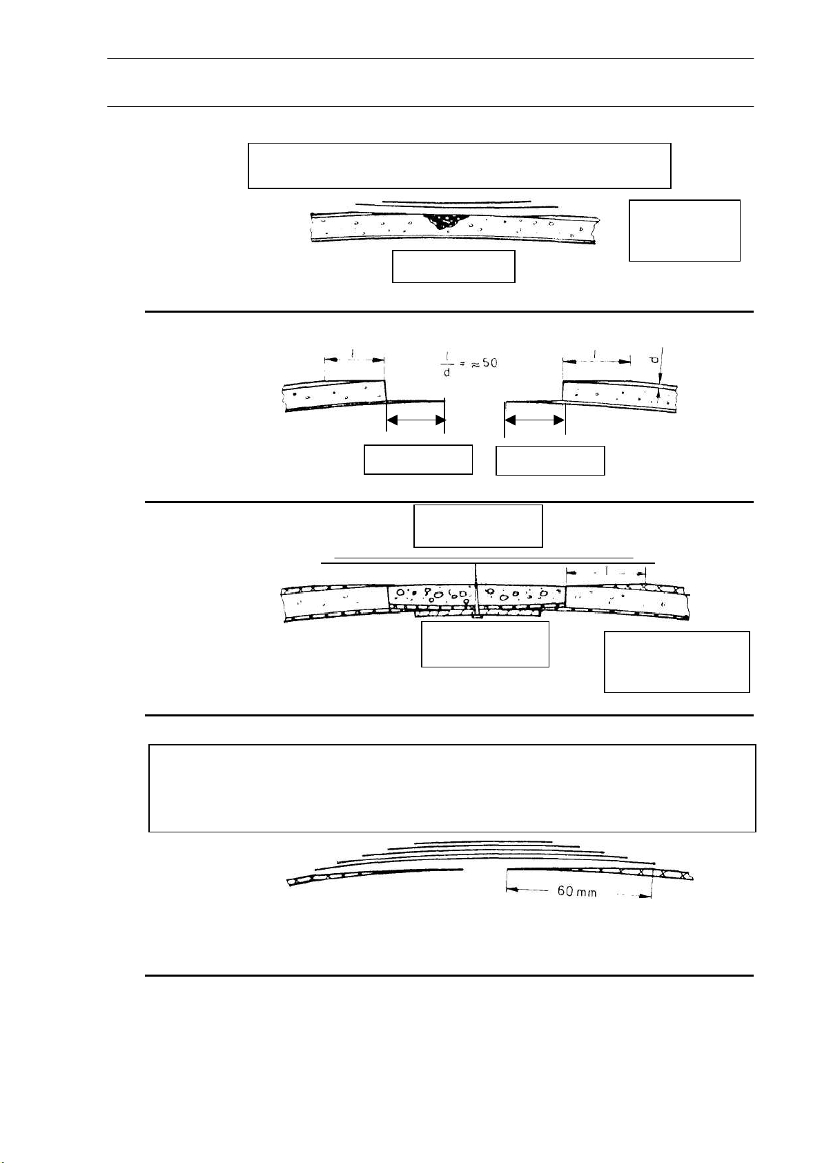
Repairs must be dirt and grease free, (Figure 1)
At room temperature the resin will cure in about ca. 8 hours.
The repair can now be ground smooth and be painted.
Warning: Grind only edge of the repaired area
b) Damage of the complete sandwich structure
In case the inner laminate is destroyed, remove outer laminate that has no adhesion to
the foam, enlarge the hole until core is firmly joined to inner skin, then it is possible to
repair the inner laminate. To repair the inner laminate properly, an additional rim of at least
20 mm must be maintained. (splice ratio approximately 1:50).
The outer laminate shall be repaired as described in section a). The inner laminate must
be carefully ground and cleaned from foam residue. (Figure 2). With minor damage a
piece of thin plywood support may be glued onto the inner skin with construction glue,
the cloth patch of the inner laminate can then be positioned. The hole will then be filled
in with resin and micro-balloons mixed with styrene-foam balls. After curing (app. 8 hours
at room temperature) the outer surface can be ground smooth and the outer cloth may be
placed in position.
The plywood support should remain in position as part of the repair. When the hole is
of large or of oblong size the plywood support should be held in place with thin nails
which can be removed later, by pushing then out from the top surface.
Warning: The plywood support must be properly fastened to avoid any wrinkles in the
cloth. (Figure 3)
Particularly with large holes in the sandwich structure, pre-fabricated foam structures shall
be considered for weight reasons instead of the micro-balloons-resin filler. Prepare a piece
of hard foam to fit exactly into the existing hole. The pores on the inside shall be closed
with resin and micro-balloons, position onto the inner cloth to cure. The structure
remains flexible to some extent (if required, warm up with hot air blower). The prefabricated structure shall be glued into the hole with thickened resin (cotton flocks or
micro-balloons). Micro-balloons are used to close and smooth the outside pores, the
repair area is then ground and the outer cloth is placed into position.
8
Rev. 9 28. Nov. 2005
Page 45

REPAIR INSTRUCTION ASTIR CS
Repair of styrene-foam supported parts
Repair shall be done in analogy to repair of GRP hard foam structure. Styrene foam
has an impermeable surface, filling of surface pores is not necessary, the fibre cloth is
held in position with pure or slightly thickened resin. With large damage let layers cure
one at a time to avoid wrinkling.
Warning: Do not use strong heat to speed up curing time, styrene foam may develop
blisters thus rendering the repair useless.
Repair of GRP laminate parts
Repair to GRP laminate is simple. Splice the area around the damaged section, position
fibre cloth in layers (largest patch first), after 2-3 hours, when the resin has partially cured
smoothen area with resin and micro balloons. Splice length per layer approximately
20mm. Ratio of laminate thickness / splice length approximately1:50. In case the splice
area is contaminated clean with Carbon Tetrachloride or Acetone. With large damage a
underlying support (plywood) should be used. Wet laminate should not bridge a gap of
more than 20 mm unsupported. The plywood support can be held in place with glue and
nails (e. g. metal fitting in fuselage) which can be removed afterwards (Figure 4).
9
Paint-Work
As soon as the laminate of the repaired section has cured, it can be ground roughly
with (80 grit) sandpaper. Uneven spots must be filled and smoothed with white polyester
filler. Grind with fine dry-grinding paper (150 grit) until a moderately smooth outer surface
is produced. Before painting, the repaired section must be cleaned from grinding dust,
residue or other foreign bodies.
When applying Gel-Coat (Schwabbellack) + hardener use a moderately stiff paint brush,
put on several thin layers, until the laminate can no longer be seen. The individual layers
should be allowed to harden and then ground with (360 grit wet paper), additional
layers should then be added and likewise ground.
The final finish should be carried out with 600 grit or 800 grit dry and wet grinding paper
and then polished with a silicon-free car polish or with hard-wax, using a polishing
machine.
Rev. 9 28. Nov. 2005
Page 46
p
yrop
y
REPAIR INSTRUCTION ASTIR CS
10
1 Lage 92110 1 Lage 92125
1 Layer 92110 1 Layer 92125
1 Lage 92110 1 Lage 92125
1 La
er 92110 1 Layer 92125
Abb.1
Fig.1
Microballoons
Abb.2
Fig. 2
_
Abb. 3
Fig. 3
Rumpfschale
Fuselage skin
1 Lage 92146 1 Lage 92110 3 Lagen 92140
1 Layer 92140 1 Layer 92110 3 Layers 92140
Abb. 4
Fig. 4
min. 20 mm
Außengewebe
Dünnes
S
errholz
min. 20 mm
Microballoons
+ Styroporkugeln
St
Kern
Core
Conticell 60
or balls
Rev. 9 28. Nov. 2005
Page 47

REPAIR INSTRUCTION ASTIR CS
Repair of Metal Fittings
a) Steel Fittings
Repair of steel fittings made of should only be completed after consultation of the
manufacturer. Welded steel fitting (push rods) made of 1.7734.4 BZW 1.0308.1 (St. 35.4).
Welding only to be carried out with WIG Welding method and with welding material 1.7734
2 (for 1.7734.4) and 1.7324.0 (for 1.0308.0 or combination of 1.7734.4 and 10308.1)
b) Aluminium Castings
Repair of aluminium castings 3.2374.6 cannot be carried out. Fractured or bent aluminium
castings must be replaced by new ones.
Warning: Bent or chipped aluminium castings must not be bent back or straightened
back to the original position.
c) Main wing / fuselage connecting rods
The main connecting rod between wing and fuselage (4x in the fuselage) contains 6
steel balls (∅ 6 mm) in each fitting. A sliding cover forces the steel balls into a groove in
the moveable lateral axis, thus securing the wings.
In case one or more steel balls are missing, the connecting rod must be exchanged.
11
Major Repairs
Major repairs must only be carried out by the manufacturer or by a manufacturer
approved repair organization. Major repairs include (amongst others)
• Broken off wings, fuselage, tail plane, control surfaces, spar stubs.
• Torn-out main fittings (fuselage tubes Ø 45 x 3)
• Fitting of the tail plane in fin. Securing bolts in the wing (Ø 18 mm), swivel bearing GE.
20, spar stub bolt Ø 20 mm).
• Destruction of main bulk (vertical frame).
• Damage to the GRP laminate (tear, splits, cracks) near the main fittings).
Rev. 9 28. Nov. 2005
Page 48
cotto
s
REPAIR INSTRUCTION ASTIR CS
Construction details of additional equipment attachment
fittings
The fittings for the oxygen bottles are built in as standard equipment on the right
hand side of the luggage compartment. Supports and quick release buckles may be
obtained from the manufacturer.
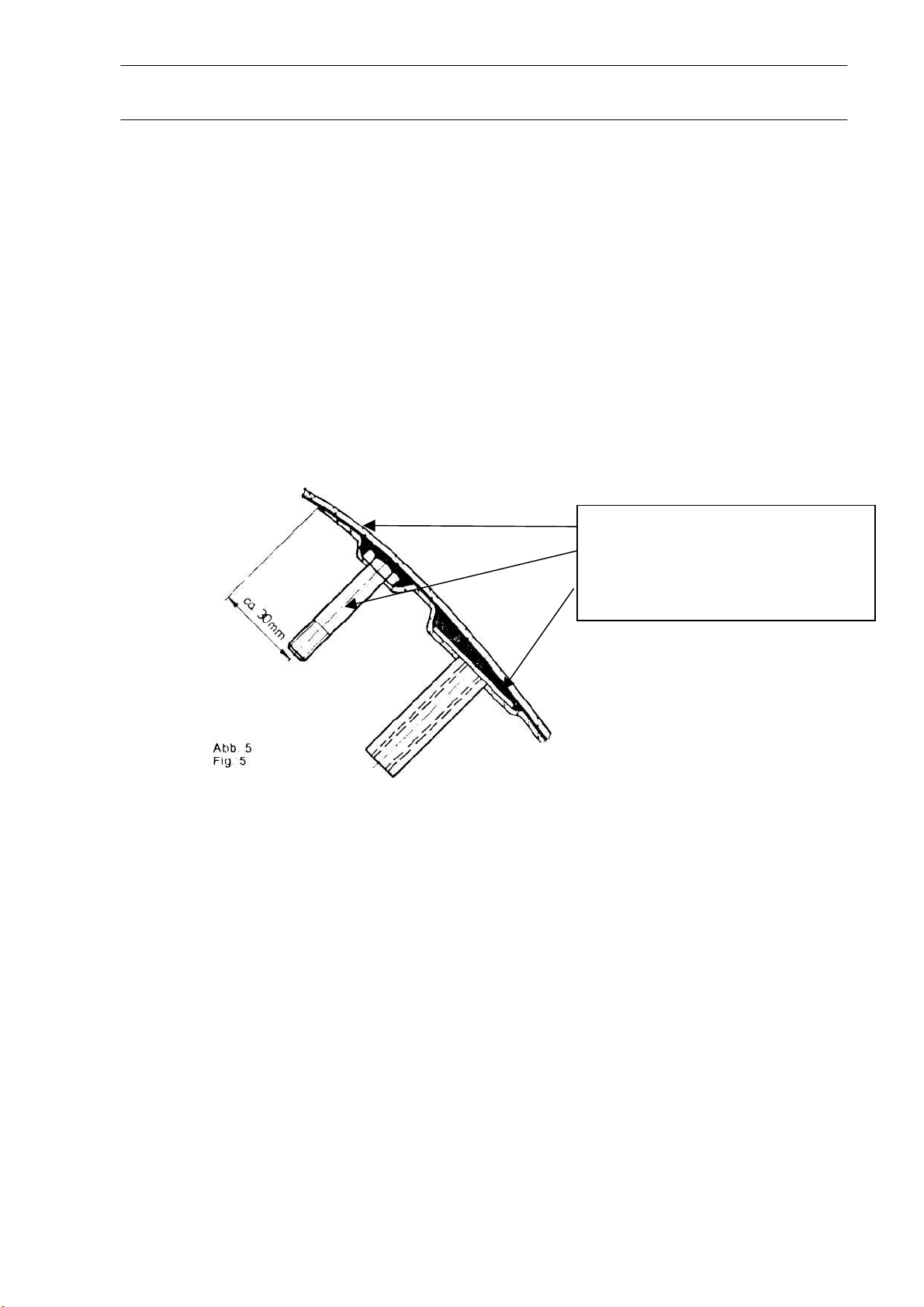
Other fitting points may be installed as shown. (Figure 5).
The fitting shall be made as shown in the drawing so as to take the weight of the
additional equipment. Under loads of up to 10g no piece of equipment must come loose
from it’s support. Following installation of additional equipment, a weight and balance
report shall be compiled to ascertain that the C of G is within the permitted limits.
Fuselage skin
Bolt
Reinforcement 2 Layers 92140
3 Layers 92 140
Resin mixed with
12
n flock
Rev. 9 28. Nov. 2005
 Loading...