


READ THIS FIRST
Models H2933, H2934,
G0447, & G0581
***IMPORTANT UPDATE***
For Machines Mfd. Since January, 2014
and Owner's Manual Revised October, 2005
For questions or help with this product contact Tech Support at (570) 546-9663 or techsupport@grizzly.com
The following changes were made to this machine since the owner's manual was printed:
• Obtained CSA certification meeting CSA C22.2 #105-1953 and UL 987-7th standards.
• Changed transformer, contactors, overload relays, terminal blocks, and wiring.
• Changed circuit requirements.
• Replaced oscillation diaphragm assembly with an air cylinder.
Note: At the top of each page is a note that indicates which page it replaces in the original manual. On the
parts list, the new parts are designated with a “V2”.
Aside from this information, all other content in the owner's manual applies and MUST be read and understood for your own safety. IMPORTANT: Keep this update with the owner's manual for future refer-
ence. For questions or help, contact our Tech Support at (570) 546-9663 or techsupport@grizzly.com.
COPYRIGHT © JUNE, 2010 BY GRIZZLY INDUSTRIAL, INC., REVISED DECEMBER, 2016 (MN)
WARNING: NO PORTION OF THIS MANUAL MAY BE REPRODUCED IN ANY SHAPE
OR FORM WITHOUT THE WRITTEN APPROVAL OF GRIZZLY INDUSTRIAL, INC.
#TS12965 PRINTED IN TAIWAN

Replaces Page 72
Main Electrical Panel and Controls Diagram
H2933
H2934
G0447
G0581
107
128
130
H2933 440V
Conversion Kit
134V2
135
139V2
111V2
112V3
126A
108
H2933
133
129
131
109
115
139
115
110V2
104
113V2
103
H2933
H2934
G0447
G0581
102
101
122
124
122
123
119
120
121
H2934
G0447
112
111
127
114
115-1
118V2
114
118V2
109
117
115
105
139
115
106
110V2
113V2
132
116V2
132
116V2
G0581
111
104
H2934 & G0447
440V Conversion Kit
134
135
112
114
111
118V2
139
115-1
127V2
115
139
139
115
132
110V2
109
104
116V2
113V2
G0581 440V
Conversion Kit
134
135
-2-
H2933, H2934, G0447, & G0581 Update
(Mfd. Since 1/14)

Replaces Page 73
REF PART # DESCRIPTION REF PART # DESCRIPTION
ELECTRICAL CONTROL BOX (G0447/H2934) 115-1 PH29348115-1 CONTACTOR SCHN LC1D25 220V
ELECTRICAL CONTROL BOX (G0581) 116V2 PH29348116V2 GROUND TERMINAL V2.03.10 (G0447/H2934)
DOOR (G0447/H2934) 116V2 PH29338116V2 GROUND TERMINAL V2.03.10 (H2933)
DOOR (G0581) 117 PS51M PHLP HD SCR M4-.7 X 30
BASE PLATE (H2933) 119 PW06 FLAT WASHER 1/4
BASE PLATE (G0447/H2934) 120 PLW02 LOCK WASHER 1/4
HEX NUT 1/4-20 122 PH29338122 PU CONNECTOR 1/2"
LOCK WASHER 1/4 123 PH29338123 PU CONNECTOR 3/4"
PHLP HD SCR M4-.7 X 8 126A PH29338126A DIGITAL AMP METER N/S
CONTACTOR SCHN LC1D38 220V
(G0447/G0581/H2934)
START SWITCH
CONTACTOR SCHN LC1D40A 220V V2.04.13
STOP SWITCH
OL RELAY SCHN LR3D32 23-32A
POWER INDICATION LIGHT
OL RELAY SCHN LRD340 30-40A V3.04.13
(H2933)
WIRE COLUMN (G0447/H2933/H2934)
FUSE 4A V2.03.10 132 P05818132 WIRE COLUMN (G0581)
OL RELAY SCHN LR3D12 5.5-8A (G0581) 139 PH29338139 CONTACTOR SCHN LC1D09 220V W/LOCK
H2933 440V Conversion Kit
H2934 440V Conversion Kit
G0447 440V Conversion Kit
G0581 440V Conversion Kit
Electrical Parts List
101 PH29338101 ELECTRICAL CONTROL BOX (H2933) 115 PH29338115 CONTACTOR SCHN LC1D09 220V
101 PH29348101
101 P05818101
102 PH29338102 HINGE 116V2 P05818116V2 GROUND TERMINAL V2.03.10 (G0581)
103 PH29348103
103 P05818103
103 PH29338103 DOOR (H2933) 118V2 PH29338118V2 TERMINAL PLATE V2.03.10
104 PH29338104
104 PH29348104
104 P05818104 BASE PLATE (G0581) 121 PB19 HEX BOLT 1/4-20 X 1/2
105 PN05
106 PLW02
107 PH29338107 CONTROL PANEL 124 PH29338124 CABLE CONNECTOR 1"
108 PS07M
109 PH29338109 CURRENT SENSOR 127 PH29348127 START DELAY LADS2 (G0447/H2934)
110V2 PH29338110V2 TRANSFORMER V2.03.10 127V2 P05818127V2 START DELAY LSD V2.03.10 (G0581)
111 PH29348111
128 PH29338128
111V2 PH29338111V2
(H2933)
112 PH29348112
(G0447/H2934)
112 P05818112 OL RELAY SCHN LR3D35 30-38A (G0581) 131 PH29338131 EMERCENGY STOP SWITCH
112V3 P0539012V3
113V2 PH29338113V2
114 PH29338114 OL RELAY SCHN LR3D08 2.5-4A
(G0447/H2933/H2934)
114 P05818114
139V2 PH29339139V2 440V CONVERSION KIT
134V2 PH29338134V2 OL RELAY SCHN LR3D325 17-25A V2.04.13
135 PH29338135 OL RELAY SCHN LR3D07 1.6-2.5A
139 PH29349139 440V CONVERSION KIT
134 PH29348134 OL RELAY SCHN LR3D21 12-18A
135 PH29338135 OL RELAY SCHN LR3D07 1.6-2.5A
129 PH29338129
130 PH29338130
132 PH29338132
133 PH29338133 COMPUTER
139 PH29349139 440V CONVERSION KIT
134 PH29348134 OL RELAY SCHN LR3D21 12-18A
135 PH29338135 OL RELAY SCHN LR3D07 1.6-2.5A
139 P05819139 440V CONVERSION KIT
134 PH29348134 OL RELAY SCHN LR3D21 12-18A
135 PH29338114 OL RELAY SCHN LR3D08 2.5-4A
H2933, H2934, G0447, & G0581 Update
(Mfd. Since 1/14)
-3-

Replaces Page 10
SECTION 1: SAFETY
For Your Own Safety, Read Instruction
Manual Before Operating This Machine
The purpose of safety symbols is to attract your attention to possible hazardous conditions.
This manual uses a series of symbols and signal words intended to convey the level of importance of the safety messages. The progression of symbols is described below. Remember that
safety messages by themselves do not eliminate danger and are not a substitute for proper
accident prevention measures. Always use common sense and good judgment.
Indicates an imminently hazardous situation which, if not avoided,
WILL result in death or serious injury.
Indicates a potentially hazardous situation which, if not avoided,
COULD result in death or serious injury.
Indicates a potentially hazardous situation which, if not avoided,
MAY result in minor or moderate injury. It may also be used to alert
against unsafe practices.
This symbol is used to alert the user to useful information about
NOTICE
proper operation of the machine.
Safety Instructions for Machinery
OWNER’S MANUAL. Read and understand this
owner’s manual BEFORE using machine.
TRAINED OPERATORS ONLY. Untrained operators have a higher risk of being hurt or killed.
Only allow trained/supervised people to use this
machine. When machine is not being used, disconnect power, remove switch keys, or lock-out
machine to prevent unauthorized use—especially
around children. Make workshop kid proof!
DANGEROUS ENVIRONMENTS. Do not use
machinery in areas that are wet, cluttered, or have
poor lighting. Operating machinery in these areas
greatly increases the risk of accidents and injury.
MENTAL ALERTNESS REQUIRED. Full mental
alertness is required for safe operation of machinery. Never operate under the influence of drugs or
alcohol, when tired, or when distracted.
ELECTRICAL EQUIPMENT INJURY RISKS. You
can be shocked, burned, or killed by touching live
electrical components or improperly grounded
machinery. To reduce this risk, only allow qualified
service personnel to do electrical installation or
repair work, and always disconnect power before
accessing or exposing electrical equipment.
DISCONNECT POWER FIRST.
nect machine from power supply BEFORE making
adjustments, changing tooling, or servicing machine.
This prevents an injury risk from unintended startup
or contact with live electrical components.
EYE PROTECTION. Always wear ANSI-approved
safety glasses or a face shield when operating or
observing machinery to reduce the risk of eye
injury or blindness from flying particles. Everyday
eyeglasses are NOT approved safety glasses.
Always discon-
-4-
H2933, H2934, G0447, & G0581 Update
(Mfd. Since 1/14)

Replaces Page 11
WEARING PROPER APPAREL. Do not wear
clothing, apparel or jewelry that can become
entangled in moving parts. Always tie back or
cover long hair. Wear non-slip footwear to reduce
risk of slipping and losing control or accidentally
contacting cutting tool or moving parts.
HAZARDOUS DUST. Dust created by machinery
operations may cause cancer, birth defects, or
long-term respiratory damage. Be aware of dust
hazards associated with each workpiece material. Always wear a NIOSH-approved respirator to
reduce your risk.
HEARING PROTECTION. Always wear hearing protection when operating or observing loud
machinery. Extended exposure to this noise
without hearing protection can cause permanent
hearing loss.
REMOVE ADJUSTING TOOLS. Tools left on
machinery can become dangerous projectiles
upon startup. Never leave chuck keys, wrenches,
or any other tools on machine. Always verify
removal before starting!
USE CORRECT TOOL FOR THE JOB. Only use
this tool for its intended purpose—do not force
it or an attachment to do a job for which it was
not designed. Never make unapproved modifications—modifying tool or using it differently than
intended may result in malfunction or mechanical
failure that can lead to personal injury or death!
AWKWARD POSITIONS. Keep proper footing
and balance at all times when operating machine.
Do not overreach! Avoid awkward hand positions
that make workpiece control difficult or increase
the risk of accidental injury.
CHILDREN & BYSTANDERS. Keep children and
bystanders at a safe distance from the work area.
Stop using machine if they become a distraction.
GUARDS & COVERS. Guards and covers reduce
accidental contact with moving parts or flying
debris. Make sure they are properly installed,
undamaged, and working correctly BEFORE
operating machine.
FORCING MACHINERY. Do not force machine.
It will do the job safer and better at the rate for
which it was designed.
NEVER STAND ON MACHINE. Serious injury
may occur if machine is tipped or if the cutting
tool is unintentionally contacted.
STABLE MACHINE. Unexpected movement during operation greatly increases risk of injury or
loss of control. Before starting, verify machine is
stable and mobile base (if used) is locked.
USE RECOMMENDED ACCESSORIES. Consult
this owner’s manual or the manufacturer for recommended accessories. Using improper accessories will increase the risk of serious injury.
UNATTENDED OPERATION. To reduce the
risk of accidental injury, turn machine OFF and
ensure all moving parts completely stop before
walking away. Never leave machine running
while unattended.
MAINTAIN WITH CARE. Follow all maintenance
instructions and lubrication schedules to keep
machine in good working condition. A machine
that is improperly maintained could malfunction,
leading to serious personal injury or death.
DAMAGED PARTS. Regularly inspect machine
for damaged, loose, or mis-adjusted parts—or
any condition that could affect safe operation.
Immediately repair/replace BEFORE operating
machine. For your own safety, DO NOT operate
machine with damaged parts!
MAINTAIN POWER CORDS. When disconnecting cord-connected machines from power, grab
and pull the plug—NOT the cord. Pulling the cord
may damage the wires inside. Do not handle
cord/plug with wet hands. Avoid cord damage by
keeping it away from heated surfaces, high traffic
areas, harsh chemicals, and wet/damp locations.
EXPERIENCING DIFFICULTIES. If at any time
you experience difficulties performing the intended operation, stop using the machine! Contact our
Technical Support at (570) 546-9663.
H2933, H2934, G0447, & G0581 Update
(Mfd. Since 1/14)
-5-

Replaces Page 12
table, getting entangled in rotating parts inside machine, or lacerated by sanding drum.
Additional Safety for Wide Belt Sanders
Serious injury or death can occur from hands getting trapped between workpiece and conveyor
Workpieces thrown by sander can strike nearby operators. Long-term respiratory damage can
occur from using sander without proper use of a respirator and an adequate dust collection
system. To minimize risk of getting hurt or killed, anyone operating machine MUST completely
heed hazards and warnings below.
FEEDING WORKPIECE. DO NOT place fingers
under bottom of workpiece while feeding it into
sander. Fingers can become pinched between
workpiece and conveyor.
ENTANGLEMENT HAZARDS. DO NOT wear
loose clothing, gloves, or jewelry, and tie back long
hair. Never reach inside operating machine or try
clearing jammed workpiece. Keep all guards in
place and secure, and all doors closed.
SANDING DRUM CONTACT. Rotating sandpaper can remove a large amount of flesh in a few
seconds. Keep hands away from rotating sanding
drum(s) during operation. Never touch moving
sandpaper on purpose.
WORKPIECE KICKBACK. A workpiece can be
ejected out the front of sander at high rate of
speed, and hit operator or bystanders. Never stand
in-line with workpiece, never feed more than one
workpiece at a time, and always adjust pressure
rollers below sanding roller.
MINIMUM STOCK DIMENSION. To avoid kickback, never sand workpieces below minimum
specifications listed in Data Sheet.
ADJUSTMENTS/MAINTENANCE. Make sure
machine is turned OFF, disconnected from power
and air, and all moving parts are completely
stopped before doing adjustments or maintenance.
SANDING DUST. Sanding creates large amounts
of dust and flying chips that can lead to eye injury
or respiratory illness. Reduce risk of these hazards
by wearing approved eye and respiratory protection when using sander.
DUST COLLECTION. Never operate without ade-
quate dust collection system in place and running.
Proper dust collection reduces dust in work area,
which decreases risk of long-term respiratory damage, but it is not a substitute for using a respirator.
Like all machinery there is potential danger
when operating this machine. Accidents are
frequently caused by lack of familiarity or
failure to pay attention. Use this machine
with respect and caution to decrease the
risk of operator injury. If normal safety precautions are overlooked or ignored, serious
personal injury may occur.
-6-
No list of safety guidelines can be complete.
Every shop environment is different. Always
consider safety first, as it applies to your
individual working conditions. Use this and
other machinery with caution and respect.
Failure to do so could result in serious personal injury, damage to equipment, or poor
work results.
H2933, H2934, G0447, & G0581 Update
(Mfd. Since 1/14)

Replaces Page 13
Before installing the machine, consider the availability and proximity of the required power supply
circuit. If an existing circuit does not meet the
requirements for this machine, a new circuit must
be installed. To minimize the risk of electrocution,
fire, or equipment damage, installation work and
electrical wiring must be done by an electrican or
qualified service personnel in accordance with all
applicable codes and standards.
Electrocution, fire, or
equipment damage may
occur if machine is not
correctly grounded and
connected to the power
The full-load current rating is the amperage a
machine draws at 100% of the rated output power.
On machines with multiple motors, this is the
amperage drawn by the largest motor or sum of all
motors and electrical devices that might operate
at one time during normal operations.
The full-load current is not the maximum amount
of amps that the machine will draw. If the machine
is overloaded, it will draw additional amps beyond
the full-load rating.
If the machine is overloaded for a sufficient length
of time, damage, overheating, or fire may result—
especially if connected to an undersized circuit.
To reduce the risk of these hazards, avoid overloading the machine during operation and make
sure it is connected to a power supply circuit that
meets the requirements in the following section.
SECTION 2: CIRCUIT
REQUIREMENTS
Availability
supply.
Full-Load Current Rating
H2933
Full-Load Current Rating at 220V ...........40.6A
Full-Load Current Rating at 440V ...........20.3A
H2934 & G0447
Full-Load Current Rating at 220V ...........54.6A
Full-Load Current Rating at 440V ........... 27.3 A
G0581
Full-Load Current Rating at 220V ...........70.5A
Full-Load Current Rating at 440V ...........35.3A
H2933, H2934, G0447, & G0581 Update
(Mfd. Since 1/14)
-7-

In Addition to Page 13
This machine is prewired to operate on a 220V
power supply circuit that has a verified ground and
meets the following requirements:
This machine can be converted to operate on a
440V power supply
Voltage Conversion
instructions) that has a verified ground and meets
the following requirements:
This machine is prewired to operate on a 220V
power supply circuit that has a verified ground and
meets the following requirements:
This machine can be converted to operate on a
440V power supply
Voltage Conversion
instructions) that has a verified ground and meets
the following requirements:
This machine can be converted to operate on a
440V power supply
Voltage Conversion
instructions) that has a verified ground and meets
the following requirements:
This machine is prewired to operate on a 220V
power supply circuit that has a verified ground and
meets the following requirements:
For your own safety and protection of
property, consult an electrician if you are
Note: The circuit requirements listed in this manual apply to a dedicated circuit—where only one
machine will be running at a time. If this machine
will be connected to a shared circuit where multiple machines will be running at the same time,
consult a qualified electrician to ensure that the
circuit is properly sized for safe operation.
A power supply circuit includes all electrical
equipment between the breaker box or fuse panel
in the building and the machine. The power supply circuit used for this machine must be sized to
safely handle the full-load current drawn from the
machine for an extended period of time. (If this
machine is connected to a circuit protected by
fuses, use a time delay fuse marked D.)
Circuit Information
unsure about wiring practices or electrical
codes in your area.
H2934 & G0447 Circuit Requirements
For 220V
Nominal Voltage ................... 220V, 230V, 240V
Cycle .......................................................... 60 Hz
Phase .................................................... 3-Phase
Power Supply Circuit ......................... 70 Amps
For 440V
(refer to
Nominal Voltage ............................. 440V, 480V
Cycle .......................................................... 60 Hz
Phase .................................................... 3-Phase
Power Supply Circuit ......................... 40 Amps
G0581 Circuit Requirements
For 220V
H2933 Circuit Requirements
For 220V
Nominal Voltage ................... 220V, 230V, 240V
Cycle .......................................................... 60 Hz
Phase .................................................... 3-Phase
Power Supply Circuit ......................... 50 Amps
For 440V
(refer to
Nominal Voltage ............................. 440V, 480V
Cycle .......................................................... 60 Hz
Phase .................................................... 3-Phase
Power Supply Circuit ......................... 30 Amps
Nominal Voltage ................... 220V, 230V, 240V
Cycle .......................................................... 60 Hz
Phase .................................................... 3-Phase
Power Supply Circuit ......................... 90 Amps
For 440V
(refer to
Nominal Voltage ............................. 440V, 480V
Cycle .......................................................... 60 Hz
Phase .................................................... 3-Phase
Power Supply Circuit ......................... 50 Amps
-8-
H2933, H2934, G0447, & G0581 Update
(Mfd. Since 1/14)
In Addition to Page 13
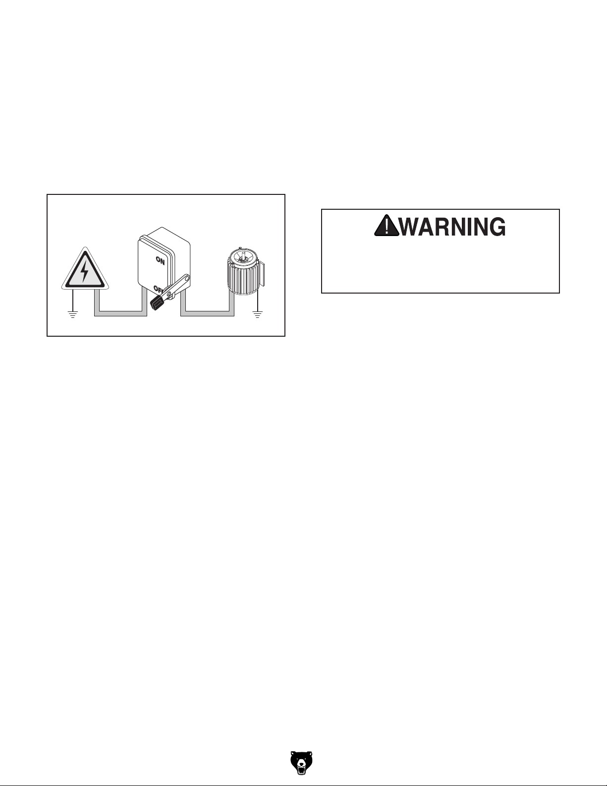
A permanently connected (hardwired) power supply is typically installed with wires running through
mounted and secured conduit. A disconnecting
means, such as a locking switch (see following
Figure
to be disconnected (isolated) from the power
supply when required. This installation must be
performed by an electrician in accordance with all
applicable electrical codes and ordinances.
Since this machine must be permanently connected to the power supply, an extension cord
cannot be used.
In the event of a malfunction or breakdown,
grounding provides a path of least resistance
for electrical current to reduce the risk of electric
shock. A permanently connected machine must
be connected to a grounded metal permanent wiring system; or to a system having an equipmentgrounding conductor. All grounds must be verified
and rated for the electrical requirements of the
machine. Improper grounding can increase the
risk of electric shock!
Connection Type
), must be provided to allow the machine
Locking
Disconnect Switch
Power
Source
Ground
Grounding Instructions
Machine
ConduitConduit
Ground
Serious injury could occur if you connect
the machine to power before completing the
setup process. DO NOT connect to power
until instructed later in this manual.
Extension Cords
Figure 6. Typical setup of a permanently
connected machine.
H2933, H2934, G0447, & G0581 Update
(Mfd. Since 1/14)
-9-
Replaces Page 14
0v 380v 415v
440v
E
0v 200v
220v
2
1
3
0
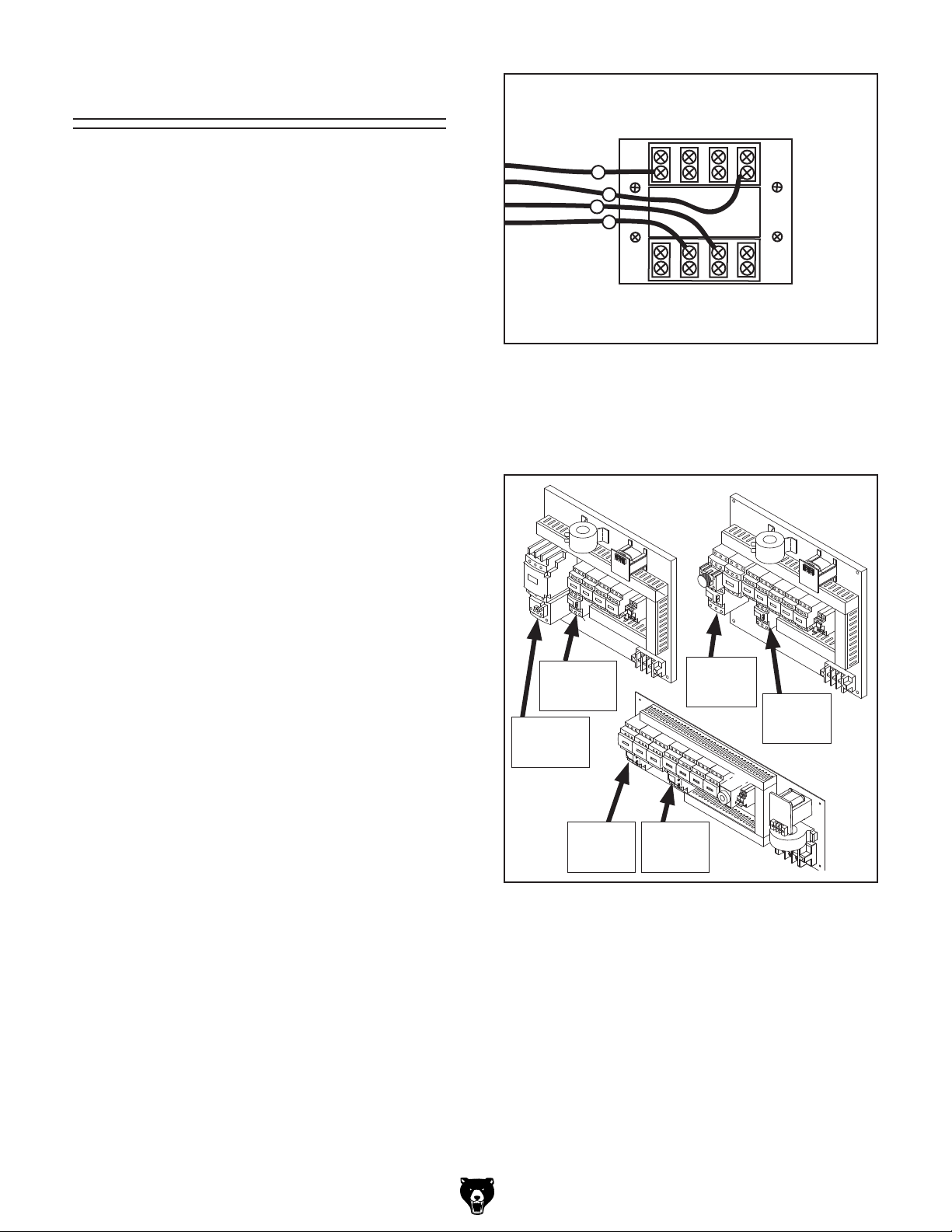
440V Connection
This machine is prewired for 220V 3-phase power
but has the capability of operating on 440V power
with a minor conversion. The conversion consists
of replacing two overload relays and rewiring each
of the three motors.
Contact the Grizzly Order Desk at (800) 523-4777
to purchase the correct 440V conversion kit for
your model that includes the necessary two overload relays:
Model Part Number
H2933 .........................................PH29339139V2
H2934 ............................................. PH29349139
G0447 ............................................. PH29349139
G0581 ................................................P05819139
H2933
H2934
G0447
G0581
Figure 7. 440V transformer connections.
4. Swap out the applicable overload relay at
the locations shown in Figure 8, and set the
amperage dial to values listed in Figure 8.
All wiring changes must be inspected by service
personnel or a qualified electrician before the
machine is connected to the power source. If, at
any time during this procedure you need help, call
Grizzly Tech Support at (570) 546-9663.
Note: When using a phase converter, the power
from the manufactured power leg (sometimes
called the wild wire) can fluctuate. Connect the
manufactured power leg to the S terminal to prevent damage to the transformer. The wire from the
S terminal can handle some fluctuation because
it goes directly to the motor. The power going to
the R and T terminals goes to the transformer and
must be consistent to prevent damage.
To wire the sander to 440V:
1. DISCONNECT MACHINE FROM POWER!
2. Open the electrical box located on the back of
the machine.
3. On the transformer, remove the wire connected to the 220V terminal and connect it to
the 440V terminal, as shown in Figures 7.
H2933
H2934
G0447
LR3D07
Set to:
(1.7A)
LR3D325
Set to:
(18A)
LR3D21
Set to:
(12.5A)
LR3D07
Set to:
(1.7A)
G0581
LR3D21
Set to:
(16A)
LR3D08
Set to:
(3A)
Figure 8. Overload relays for 440V.
5. Wire the sanding belt, conveyor belt, and
table elevation motors as shown in the diagrams on Page 55 of the owner's manual.
-10 -
H2933, H2934, G0447, & G0581 Update
(Mfd. Since 1/14)

Replaces Page 43
Control Panel Electrical Diagram
(H2933/H2934/G0447)
U 1
V 1 W 1 U 2
OUT TO
SANDING
MOTOR
TABLE UP/DOWN
SAFETY LIMIT
SWITCH
TABLE UP/DOWN
SAFETY LIMIT
SWITCH
TABLE HEIGHT SENSOR
W 2 18
V 2
16
2
1
4
3
4
3
1
2
B L U E
B L A C K
17
16
19
13
1 2
11
12
18
1 3 1 4 1 5 1 6 1 7 1 8 1 9 2 0 2 1 2 2
7
8 6 5
10
9
DIGITAL AMP
METER
DIGITAL PANEL
5
3 3
2
14
1 5
2
3
1 4
1 5
1
2
EMERGENCY
STOP AND
BELT TENSION
LIMIT SWITCHES
1
2
BELT TRACKING
LIMIT
SWITCH
BELT TRACKING
LIMIT
SWITCH
1
2
1
2
B L A C K
B L U E
B
1 4
1 3
1 4
1 3
1 3
1 0 9
A
2 2
2 1
2 2
2 1
2 2
2 1
O V
8
7
6 5
4
7
6
2
3
X 2
X 1
X 2
X 1
3
2
X 2
X 1
1 4
1 3
1
1 3
1 4
1 1
1 0
SANDING
BELT START
SWITCH
CONVEYOR
BELT START
SWITCH
POWER
9
8
LAMP
1 2
V
1 1
5
4
3
3
5
4
3
3
5
4
3
3
5
4
3
3
SANDING
BELT STOP
SWITCH
CONVEYOR
BELT STOP
SWITCH
EMERGENCY
STOP
BUTTON
1 4
5
H2933, H2934, G0447, & G0581 Update
(Mfd. Since 1/14)
-11-

Replaces Page 44
Control Panel Electrical Diagram
(G0581)
U 1
V 1 W 1 U 2
OUT TO
SANDING MOTOR
TABLE UP/DOWN
SAFETY LIMIT
SWITCH
TABLE UP/DOWN
SAFETY LIMIT
SWITCH
TABLE HEIGHT SENSOR
W 2 2
V 2
2
1
4
3
4
3
1
2
B L U E
B L A C K
3
3
4
1 2
8
8
5
1 3 1 4 1 5 1 6 1 7 1 8 1 9 2 0 2 1 2 2
7
2 2 2 3 6
4
5
DIGITAL AMP
METER
DIGITAL PANEL
9
1 0 1 1
1 2
1 3
3
2
1 4
1 4
1 5
1 5
2 0 2 1
EMERGENCY STOP
PUSH-PANEL LIMIT
SWITCH
BELT TENSION
LIMIT
SWITCH
BELT TRACKING
LIMIT
SWITCH
BELT TRACKING
LIMIT
SWITCH
1
2
1
2
B L A C K
B L U E
B
1 4
1 3
1 4
1 3
1 3
1 0 9
A
2 2
2 1
2 2
2 1
2 2
2 1
O V
8
7
6 5
4
7
3
6
1 3
2
3
X 2
X 1
9
X 2
X 1
3
2
X 2
X 1
1 3
1
1 4
1 3
1 4
1 0
SANDING
BELT START
SWITCH
CONVEYOR
BELT START
SWITCH
POWER
LAMP
1 2
9
1 1
1 2
V
1 1
8
1
4
2
3
3
8
4
3
3
8
1
4
2
3
3
8
4
3
3
SANDING
BELT STOP
SWITCH
CONVEYOR
BELT STOP
SWITCH
EMERGENCY
STOP
BUTTON
1 4
8
-12-
H2933, H2934, G0447, & G0581 Update
(Mfd. Since 1/14)

Replaces Page 46
Electrical Box Wiring Diagram (H2933)
Grnd
H2933, H2934, G0447, & G0581 Update
(Mfd. Since 1/14)
-13-

Replaces Page 48
Electrical Box Wiring Diagram (G0447/H2934)
Grnd
-14-
H2933, H2934, G0447, & G0581 Update
(Mfd. Since 1/14)

Replaces Page 50
Electrical Box Wiring Diagram (G0581)
Grnd
H2933, H2934, G0447, & G0581 Update
(Mfd. Since 1/14)
-15-

Replaces Page 52
General Wiring Diagram (H2933)
-16-
H2933, H2934, G0447, & G0581 Update
(Mfd. Since 1/14)

Replaces Page 53
General Wiring Diagram (G0477/H2934)
H2933, H2934, G0447, & G0581 Update
(Mfd. Since 1/14)
-17-

Replaces Page 54
General Wiring Diagram (G0581)
-18-
H2933, H2934, G0447, & G0581 Update
(Mfd. Since 1/14)

104-1
301
108
105
104
208
202
206
Replaces Page 68
Upper Roller System Diagram
205
207
320
106
302
305
204
203
111
304
310
115-1
107
201
304
115
131
303
115-1
113
112
111
116
202
128
116-2
117
131
119
115
130
130
131
132
118
109
203
129
205
208
204
306
120
322
(H2933, H2934, G0447)
103
121
127
124
135
323
(H2933, H2934, G0447)
324
131
321
122
133
126
123
134
136
125
323
(G0581)
322
(G0581)
323
101-1
Previous Version Air Cylinder
H2933, H2934, & G0447
New Version Air Cylinder (P/N 323)
101
108
103-1
110
G0581 New Version
Air Cylinder (P/N 323)
104
104-1
112
101-1
113
103-1
202
111
101
G0581
201
103
137
142
141
140
139
138
H2933, H2934, G0447, & G0581 Update
(Mfd. Since 1/14)
-19-

Replaces Page 69
Upper Roller System Parts List
REF PART # DESCRIPTION REF PART # DESCRIPTION
101 PH29336101 SQUARE FRAME REAR (H2933)
101 PH29346101 SQUARE FRAME REAR (H2934)
101 P04476101 SQUARE FRAME REAR (G0447)
101 P05816101 SQUARE FRAME REAR (G0581)
101-1 PH29336101-1 SQUARE FRAME FRONT (H2933)
101-1 PH29346101-1 SQUARE FRAME FRONT (H2934)
101-1 P04476101-1 SQUARE FRAME FRONT (G0447)
101-1 P05816101-1 SQUARE FRAME FRONT (G0581)
103 PH29336103 FRAME SEAL RIGHT (H2933)
103 PH29346103 FRAME SEAL RIGHT (H2934)
103 P04476103 FRAME SEAL RIGHT (G0447)
103 P05816103 FRAME SEAL RIGHT (G0581)
103-1 PH29336103-1 FRAME SEAL FRONT (H2933)
103-1 PH29346103-1 FRAME SEAL FRNT RT (H2934)
103-1 P04476103-1 FRAME SEAL FRNT RT (G0447)
103-1 P05816103-1 FRAME SEAL FRNT RT (G0581)
104 PH29336104 FRAME SEAL LEFT (H2933)
104 PH29346104 FRAME SEAL LEFT (H2934)
104 P04476104 FRAME SEAL LEFT (G0447)
104 P05816104 FRAME SEAL LEFT (G0581)
104-1 PH29336104-1 FRAME SEAL FRNT LFT (H2933)
104-1 PH29346104-1 FRAME SEAL FRNT LFT (H2934)
104-1 P04476104-1 FRAME SEAL FRNT LFT (G0447)
104-1 P05816104-1 FRAME SEAL FRNT LFT (G0581)
105 PFH03 FLAT HD SCR 1/4-20 X 1/2
106 PLW04 LOCK WASHER 3/8
107 PB18 HEX BOLT 3/8-16 X 1
108 PLW07 LOCK WASHER 1/2
109 PB53 HEX BOLT 1/2-12 X 1
110 PS04 PHLP HD SCR 1/4-20 X 1/2
111 PSB07 CAP SCREW 5/16-18 X 3/4
112 PB03 HEX BOLT 5/16-18 X 1
113 PH29336113 AIR CYLINDER
115 PH29336115 LIMIT SWITCH W/CERAMIC TIP
115-1 PH29336115-1 CERAMIC TIP
116 PH29336116 LIMIT SWITCH W/PLASTIC TIP
116-2 PH29336116-2
117 PH29336117 LIMIT SWITCH HOLDER
118 PH29336118 AIR SENSOR NOZZLE FEMALE
119 PH29336119 AIR FORK
120 PH29336120 AIR SENSOR NOZZLE MALE
121 PH29336121 THROTTLE VALVE
122 PH29336122 THROTTLE VALVE BASE
123 PH29336123 PLATE
124 PH29336124 HOUSING ASSEMBLY
125 PH29336125 OIL CAP
LIMIT SWITCH HOLDER, L-TYPE
126 PH29336126 ALUMINUM PLATE
127 PS02M PHLP HD SCR M4-.7 X 12
128 PH29336128 SHUTDOWN BRACKET
129 PN11 HEX NUT 3/8-24
130 PW07 FLAT WASHER 5/16
131 PLW01 LOCK WASHER 5/16
132 PB09 HEX BOLT 5/16-18 X 1/2
133 PS08 PHLP HD SCR 10-24 X 3/4
134 PN07 HEX NUT 10-24
135 PH29336135 CONNECTOR OF OIL CAP
136 PH29336136 SHAFT OF OIL CAP
137 P0581137 BRACKET (G0581)
138 P0581138 BRACKET (G0581)
139 PSB08 CAP SCREW 5/16-18 X 1-1/2
140 PSB76 CAP SCREW 1/2-12 X 1-1/2
141 PLW07 LOCK WASHER 1/2
142 PB53 HEX BOLT 1/2-12 X 1
201 PH29336201 BRACKET (H2933, H2934, G0447)
201 P05816201 BRACKET (G0581)
202 P05816202 UPPER ROLLER (H2933)
202 PH29336202 UPPER ROLLER (H2934/G0447)
202 PH29346202 UPPER ROLLER (G0581)
203 PH29336203 UPPER ROLLER BRACKET
204 P99625204 BEARING UCC205
205 PSS02M SET SCREW M6-1 X 6
206 PSB33 CAP SCREW 10-24 x 3/4
207 PLW04 LOCK WASHER 3/8
208 PH29336208 GREASE FITTING W/DUST CAP
301 P05816301 KNOB
302 PH29336302 ECCENTRIC ROD
303 PSB79 CAP SCREW 1/2-12 X 3-1/2
304 PW01 FLAT WASHER 1/2
305 PH29336305 ECCENTRIC PIECE
306 PH29336306 CLEVIS ASSEMBLY
310 PN06 HEX NUT 1/2-12
320 PH29336320 ECCENTRIC SHAFT FRAME
321 PN02 HEX NUT 5/16-18
322 PH29339124 CONNECTOR 1/4N X 1/8T X 90DEG
(H2933, H2934, G0447)
322 P05819124 CONNECTOR 1/4N X 1/4T X 90DEG
(G0581)
323 P0539499V2 OSCILLATING AIR CYLINDER
30 X 4 (H2933, H2934, G0447)
323 P05816323 OSCILLATING AIR CYLINDER
50 X 4 (G0581)
324 PB11 HEX BOLT 5/16-18 X 1-1/2
-20-
H2933, H2934, G0447, & G0581 Update
(Mfd. Since 1/14)

Replaces Page 74 & 75
Belt Oscillation System
(For G0581 Only)
122
124
124
124
123
131
132
136
119
122
120
124
123
125
123
135
116
124
124
132
138
135
113
131
112
120
111
113
(For G0581 Only)
138
133
133
113
116
134
115
117
114
137
140
136
119
115
111
114
113
123
134
129
125
123
116
135
102
117
128
103
101
109
127
116
137
104
107
106
105
IN
108
110
123
REF PART # DESCRIPTION REF PART # DESCRIPTION
101 PH29339101 FILTER CUP 122 PH29339122 AIR SWITCH
102 PH29339102 REGULATOR W/GAUGE 123 PH29339123 CONNECTOR 1/4N X 1/8T
103 PH29339103 CONNECTOR, BRONZE
104 PH29339104 FLEXIBLE HOSE 6MM
105 PH29339105 AIR SWITCH
106 PH29339106 ELBOW
107 PH29339107 PHLP HD SCR 10-24 x 5/8 125 PH29339125 BUFFER
108 PH29339108 ELBOW 5/16N X 1/8T 90º 127 PH29339127 CONNECTOR 5/16N X 1/8T 90º
109 PH29339109 SOLENOID VALVE 128 PH29339128 8MM FLEXIBLE HOSE
110 PH29339110 T-FITTING 5/16N X 5/16N X 1/8T 129 PH29339129 8MM FLEXIBLE HOSE
111 PH29339111 CONNECTOR 5/16 X 1/4T BRONZE 131 PH29339131 6MM FLEXIBLE HOSE
112 PH29339112 MANIFOLD 1/4N 2-PORT 132 PH29339132 6MM FLEXIBLE HOSE
113 PH29339113 CONNECTOR 1/4N X 1/4T 133 PH29339133 6MM FLEXIBLE HOSE
114 PH29339114 ELBOW 1/4T X 1/8T 90º 134 PH29339134 6MM FLEXIBLE HOSE
115 PH29339115 CONNECTOR 1/4N X 1/8T 90º 135 PH29339135 6MM FLEXIBLE HOSE
116 PH29339116 CONNECTOR 1/4N X 1/8T 90º 136 PH29339136 6MM FLEXIBLE HOSE
117 PH29339117 THROTTLE VALVE 137 PH29339137 6MM FLEXIBLE HOSE
119 PH29339119 CONNECTOR 1/4N 138 PH29339138 6MM FLEXIBLE HOSE
120 PH29339120 CONNECTOR 1/4N X 3/8T 140 PH29339140 MANIFOLD 1/4N 3-PORT
124 PH29339124
124 P05819124 CONNECTOR 1/4N X 1/8T 90º
CONNECTOR 1/4N X 1/8T 90º
(H2933,H2934, G0447)
(H2933,H2934, G0447)
H2933, H2934, G0447, & G0581 Update
(Mfd. Since 1/14)
-21-


MODEL
H2933/H2934/G0447/G0581
DOUBLE-HEAD WIDE-BELT SANDER
INSTRUCTION MANUAL
COPYRIGHT © SEPTEMBER 2005 BY GRIZZLY INDUSTRIAL, INC. REVISED JUNE 2006.
WARNING: NO PORTION OF THIS MANUAL MAY BE REPRODUCED IN ANY SHAPE
OR FORM WITHOUT THE WRITTEN APPROVAL OF GRIZZLY INDUSTRIAL, INC.
#CR
7108 PRINTED IN TAIWAN


Table of Contents
INTRODUCTION ............................................................................................................................... 3
Foreword .................................................................................................................................... 3
Contact Info ................................................................................................................................ 3
Control Panel Features .............................................................................................................. 4
External Features ....................................................................................................................... 4
Internal Features ........................................................................................................................ 5
Machine Data Sheet (H2933)..................................................................................................... 6
Machine Data Sheet (H2934)..................................................................................................... 7
Machine Data Sheet (G0447) .................................................................................................... 8
Machine Data Sheet (G0581) .................................................................................................... 9
SECTION 1: SAFETY ..................................................................................................................... 10
Safety Instructions for Machinery ............................................................................................. 10
Additional Safety for Wide Belt Sanders .................................................................................. 12
SECTION 2: CIRCUIT REQUIREMENTS ...................................................................................... 13
220V/440V Connection ............................................................................................................ 13
Extension Cords ....................................................................................................................... 13
Grounding ................................................................................................................................. 13
Amperage Loads ...................................................................................................................... 13
440V Connection ...................................................................................................................... 14
SECTION 3: SET UP ...................................................................................................................... 15
Unpacking ................................................................................................................................ 15
Inventory ................................................................................................................................... 15
Hardware Chart ........................................................................................................................ 16
Clean Up .................................................................................................................................. 17
Site Considerations .................................................................................................................. 17
Beginning Assembly ................................................................................................................. 18
Air Line Installation ................................................................................................................... 18
Dust Collection ......................................................................................................................... 18
Sanding Belt ............................................................................................................................. 19
Pressure Rollers ....................................................................................................................... 20
Start Up .................................................................................................................................... 20
Recommended Adjustments .................................................................................................... 21
SECTION 4: OPERATIONS ........................................................................................................... 22
Operation Safety ...................................................................................................................... 22
Choosing Sandpaper................................................................................................................ 22
Table Movement....................................................................................................................... 23
Adjusting Feed Rate ................................................................................................................. 23
Amp Draw Meter ...................................................................................................................... 24
Sanding Workpiece .................................................................................................................. 25
Platen Adjustment .................................................................................................................... 25
SECTION 5: ACCESSORIES ......................................................................................................... 26
SECTION 6: MAINTENANCE......................................................................................................... 27
General ..................................................................................................................................... 27
Schedule .................................................................................................................................. 27
Sanding Belts ........................................................................................................................... 28
Air System ................................................................................................................................ 28
Dust and Water Traps .............................................................................................................. 28

SECTION 7: SERVICE .................................................................................................................. 29
Table Calibration ...................................................................................................................... 29
Platen Service .......................................................................................................................... 29
Brake Service ........................................................................................................................... 30
Oscillation Timing .................................................................................................................... 31
Oscillation Speed ..................................................................................................................... 33
Table Parallelism ...................................................................................................................... 33
Pressure Rollers ....................................................................................................................... 34
V-Belt Adjustment..................................................................................................................... 35
Conveyor Belt Replacement .................................................................................................... 36
Feed Belt Tension .................................................................................................................... 38
Feed Belt Tracking ................................................................................................................... 38
Air System Diagram ................................................................................................................. 39
Troubleshooting ........................................................................................................................ 40
Tool Box and Accessories Diagram ......................................................................................... 56
Tool Box and Accessories Parts List ....................................................................................... 57
Sanding Motor System Diagram .............................................................................................. 58
Sanding Motor System Parts List ............................................................................................. 59
Table Lift System Diagram ....................................................................................................... 60
Table Lift System Parts List ..................................................................................................... 61
Conveyor System Diagram ...................................................................................................... 62
Conveyor System Parts List ..................................................................................................... 63
Feed, Drum, and Pressure Roller Diagram .............................................................................. 64
Feed, Drum, and Pressure Roller Parts List ............................................................................ 65
Sanding Drum, and Platen Diagram ........................................................................................ 66
Sanding Drum, and Platen Parts List ....................................................................................... 67
Upper Roller System Diagram ................................................................................................. 68
Upper Roller System Parts List ................................................................................................ 69
Cabinet Assembly Diagram ...................................................................................................... 70
Main Electrical Panel and Controls Diagram ........................................................................... 72
Main Electrical Panel and Controls Parts List .......................................................................... 73
Belt Oscillation System Diagram .............................................................................................. 74
Belt Oscillation System Parts List ............................................................................................ 75
Machine Label Diagram ........................................................................................................... 76
Machine Label List ................................................................................................................... 77
WARRANTY & RETURNS ............................................................................................................. 78
-2- H2933/H2934/G0447/G0581 Wide Belt Sander

INTRODUCTION
Foreword
We are proud to offer the H2933/H2934/G0447/
G0581 Wide Belt Sander. This machine is part
of a growing Grizzly family of fine woodworking
machinery. When used according to the guidelines set forth in this manual, you can expect
years of trouble-free, enjoyable operation and
proof of Grizzly’s commitment to customer satisfaction.
We are pleased to provide this manual with the
H2933/H2934/G0447/G0581 Wide Belt Sander.
It was written to guide you through assembly,
review safety considerations, and cover general
operating procedures.
The specifications, drawings, and photographs
illustrated in this manual represent the H2933/
H2934/G0447/G0581 Wide Belt Sander as sup-
plied when the manual was prepared. For your
convenience, we always keep current Grizzly
manuals available on our website at www.griz-
zly.com. Any updates to your machine will be
reflected in these manuals as soon as they are
complete.
Contact Info
If you have any comments regarding this manual,
please write to us at the address below:
C
/O Technical Documentation Manager
We stand behind our machines. If you have any
service questions or parts requests, please call or
write us at the location listed below.
Grizzly Industrial, Inc.
P.O. Box 2069
Bellingham, WA 98227-2069
Grizzly Industrial, Inc.
1203 Lycoming Mall Circle
Muncy, PA 17756
Phone: (570) 546-9663
Fax: (800) 438-5901
E-Mail: techsupport@grizzly.com
Web Site: http://www.grizzly.com
H2933/H2934/G0447/G0581 Wide Belt Sander -3-

Control Panel
Features
External Features
A
B
C
D
E
F L
G
H
K
M
E
F
A
C
I
J
B
Figure 2. Front View.
G
H
D
Figure 1. Control Panel.
A. Digital Amp Draw Meter
B. Table-Height Digital Readout
C. Table Up Key
D. Table Down Key
E. Sanding Belt Start Button
F. Conveyor Belt Start Button
G. Power Light
H. Table Set (Enter) Key
I. Table Start Key
J. Table Stop Key
K. Sanding Belt Stop Button
L. Feed Belt Stop Button
M. Emergency Stop Button
I
Figure 3. Rear View.
A. Control Panel
B. Table Height Handwheel
C. Emergency Stop Push-Panel
D. 4" Dust Collection Ports
E. Amperage Load Chart
F. Digital Table Height Key Pad
G. Conveyor Speed Control
H. Air Pressure Regulator
I. Main Wiring Box
-4- H2933/H2934/G0447/G0581 Wide Belt Sander

Internal Features
E
A
A
B
J
I
F
C
B
D
C
Figure 4. Inside the left access door.
A. Belt Tension Knob
B. Platen Adjustment Lever
C. Platen Adjustment Lock Lever
D. Lock Post Release Lever
E. Tracking Adjustment Knob
G
D
Figure 5. Inside the right access door.
F. Upper Rollers
G. Airflow Adjustment Knob
H. Speed Control Adjustment Knob
I. Air Fork and Air Jet
J. Diaphragm Valve Assembly
H
H2933/H2934/G0447/G0581 Wide Belt Sander -5-

Machine Data Sheet (H2933)
MACHINE DATA
SHEET
Customer Service #: (570) 546-9663 • To Order Call: (800) 523-4777 • Fax #: (800) 438-5901
MODEL H2933 24" DOUBLE-HEAD
WIDE-BELT SANDER
Design Type ........................................................................................................................Floor Model
Overall Dimensions:
Overall Height ...................................................................................................................... 711⁄2"
Overall Width .............................................................................................................................42"
Overall Depth .........................................................................................................................591⁄2"
Conveyor Height at Lowest Setting ...........................................................................................32''
Net Weight ....................................................................................................................... 2314 lbs.
Shipping Weight .............................................................................................................. 2645 lbs.
Footprint .......................................................................................................................... 40" x 31"
Capacities:
Maximum Board Width ..............................................................................................................24"
Maximum Board Thickness .........................................................................................................6"
Minimum Board Length .............................................................................................................14"
Minimum Board Thickness .........................................................................................................
Drum Speed (Front) ...................................................................................................... 3543 FPM
Drum Speed (Rear) ....................................................................................................... 2565 FPM
Conveyor Speed ........................................................................................................... 14-60 FPM
Dust Ports .......................................................................................................................... Four, 4''
Drum Diameter ......................................................................................... (Front 7.87"), (Rear 4")
Sanding Drum Motor:
Type ......................................................................................................................TEFC Induction
Horsepower .......................................................................................................................... 15 HP
Voltage / Phase / Cycle ........................................................... 220V / 440V Three-Phase ⁄ 60 HZ
Amps ................................................................................................................................ 36 / 18A
RPM ..............................................................................................................................1725 RPM
Power Transfer to Drums ........................................................................... Triple and Twin V-Belt
Conveyor Feed Motor:
Type ......................................................................................................................TEFC Induction
Horsepower ............................................................................................................................ 1 HP
Voltage / Phase / Cycle ........................................................... 220V / 440V Three-Phase ⁄ 60 HZ
Amps .............................................................................................................................. 3.4 / 1.7A
RPM ..............................................................................................................................1725 RPM
Power Transfer ..................................................................................................................... V-Belt
Table Lift Motor:
Type ......................................................................................................................TEFC Induction
Horsepower ...........................................................................................................................
Voltage / Phase / Cycle ........................................................... 220V / 440V Three-Phase ⁄ 60 HZ
Amps .............................................................................................................................. 1.2 / 0.6A
RPM ..............................................................................................................................1725 RPM
Power Transfer ..................................................................................................................... V-Belt
General Construction:
Cabinet ...................................................................................................................................Steel
Operating Air Pressure ........................................................................................................ 75 PSI
Sanding Belt Oscillation ................................................................................................ Adjustable
Emergency Sanding Belt Brake .............................................................................. Air Disc Brake
Control Panel ................................................. Push Button Motor Controls, and Amp Load Meter
Sanding Belt .................................................................................................................... 24" x 60"
Graphite Size .................................................................................................................. 24" x 3.5"
Sanding Type .............................................................................................Drum and Platen Style
1
⁄4 HP
1
⁄4"
Specifications, while deemed accurate, are not guaranteed.
-6- H2933/H2934/G0447/G0581 Wide Belt Sander

MACHINE DATA
Machine Data Sheet (H2934)
SHEET
Customer Service #: (570) 546-9663 • To Order Call: (800) 523-4777 • Fax #: (800) 438-5901
MODEL H2934 37" DOUBLE-HEAD
WIDE-BELT SANDER
Design Type ........................................................................................................................Floor Model
Overall Dimensions:
Overall Height ...................................................................................................................... 711⁄2"
Overall Width .............................................................................................................................54"
Overall Depth .........................................................................................................................591⁄2"
Conveyor Height at Lowest Setting ...........................................................................................32''
Net Weight ....................................................................................................................... 3086 lbs.
Shipping Weight .............................................................................................................. 3527 lbs.
Footprint .......................................................................................................................... 52" x 31"
Capacities:
Maximum Board Width ........................................................................................................... 361⁄2"
Maximum Board Thickness .........................................................................................................6"
Minimum Board Length .............................................................................................................14"
Minimum Board Thickness .........................................................................................................1⁄4"
Drum Speed (Front) ...................................................................................................... 3543 FPM
Drum Speed (Rear) ....................................................................................................... 2565 FPM
Conveyor Speed ........................................................................................................... 14-60 FPM
Dust Ports ...........................................................................................................................Six, 4"
Drum Diameter ......................................................................................... (Front 7.87"), (Rear 4")
Sanding Drum Motor:
Type ......................................................................................................................TEFC Induction
Horsepower .......................................................................................................................... 20 HP
Voltage / Phase / Cycle ........................................................... 220V / 440V Three-Phase ⁄ 60 HZ
Amps ................................................................................................................................ 50 / 25A
RPM ..............................................................................................................................1725 RPM
Power Transfer to Drums ........................................................................... Twin and Triple V-Belt
Conveyor Feed Motor:
Type ......................................................................................................................TEFC Induction
Horsepower ............................................................................................................................ 1 HP
Voltage / Phase / Cycle ........................................................... 220V / 440V Three-Phase ⁄ 60 HZ
Amps .............................................................................................................................. 3.4 / 1.7A
RPM ..............................................................................................................................1725 RPM
Power Transfer ..................................................................................................................... V-Belt
Table Lift Motor:
Type ......................................................................................................................TEFC Induction
Horsepower ......................................................................................................................... 1⁄4 HP
Voltage / Phase / Cycle ........................................................... 220V / 440V Three-Phase ⁄ 60 HZ
Amps .............................................................................................................................. 1.2 / 0.6A
RPM ..............................................................................................................................1725 RPM
Power Transfer ..................................................................................................................... V-Belt
General Construction:
Cabinet ...................................................................................................................................Steel
Operating Air Pressure ........................................................................................................ 75 PSI
Sanding Belt Oscillation ................................................................................................ Adjustable
Emergency Sanding Belt Brake .............................................................................. Air Disc Brake
Control Panel ................................................. Push Button Motor Controls, and Amp Load Meter
Sanding Belt .................................................................................................................... 37" x 60"
Graphite Size .................................................................................................................. 37" x 3.5"
Sanding Type .............................................................................................Drum and Platen Style
Specifications, while deemed accurate, are not guaranteed.
H2933/H2934/G0447/G0581 Wide Belt Sander -7-

Machine Data Sheet (G0447)
MACHINE DATA
SHEET
Customer Service #: (570) 546-9663 • To Order Call: (800) 523-4777 • Fax #: (800) 438-5901
MODEL G0447 37" DOUBLE-HEAD
TALL WIDE-BELT SANDER
Design Type ........................................................................................................................Floor Model
Overall Dimensions:
Overall Height W/Dust Ports .................................................................................................... 79"
Overall Height W/O Dust Ports .................................................................................................73"
Overall Width ..........................................................................................................................531⁄2"
Overall Depth .........................................................................................................................591⁄2"
Conveyor Height at Lowest Setting ...........................................................................................32''
Net Weight ....................................................................................................................... 3197 lbs.
Shipping Weight .............................................................................................................. 3637 lbs.
Footprint .......................................................................................................................... 52" x 31"
Capacities:
Maximum Board Width ........................................................................................................... 361⁄2"
Maximum Board Thickness .........................................................................................................6"
Minimum Board Length .............................................................................................................11"
Minimum Board Thickness .........................................................................................................1⁄4"
Drum Speed (Front) ...................................................................................................... 3543 FPM
Drum Speed (Rear) ....................................................................................................... 2554 FPM
Conveyor Speed ........................................................................................................... 17-63 FPM
Dust Ports ............................................................................................................................ Six, 4''
Drum Diamiter .......................................................................................... (Front 7.87"), (Rear 4")
Sanding Drum Motor:
Type ......................................................................................................................TEFC Induction
Horsepower .......................................................................................................................... 20 HP
Voltage / Phase / Cycle ........................................................... 220V / 440V Three-Phase ⁄ 60 HZ
Amps ................................................................................................................................ 50 / 25A
RPM ..............................................................................................................................1725 RPM
Power Transfer to Drums ........................................................................................... Triple V-Belt
Conveyor Feed Motor:
Type ......................................................................................................................TEFC Induction
Horsepower ............................................................................................................................ 1 HP
Voltage / Phase / Cycle ........................................................... 220V / 440V Three-Phase ⁄ 60 HZ
Amps .............................................................................................................................. 3.4 / 1.7A
RPM ..............................................................................................................................1725 RPM
Power Transfer ........................................................................................... Twin and Triple V-Belt
Table Lift Motor:
Type ......................................................................................................................TEFC Induction
Horsepower ......................................................................................................................... 1⁄4 HP
Voltage / Phase / Cycle ........................................................... 220V / 440V Three-Phase ⁄ 60 HZ
Amps .............................................................................................................................. 1.2 / 0.6A
RPM ..............................................................................................................................1725 RPM
Power Transfer ..................................................................................................................... V-Belt
General Construction:
Cabinet ...................................................................................................................................Steel
Operating Air Pressure ........................................................................................................ 75 PSI
Sanding Belt Oscillation ................................................................................................ Adjustable
Emergency Sanding Belt Brake .............................................................................. Air Disc Brake
Control Panel ................................................. Push Button Motor Controls, and Amp Load Meter
Sanding Belt .................................................................................................................... 37" x 75"
Graphite Size ............................................................................................................... 37.8" x 3.5"
Sanding Type ..............................................................................................................Platen Style
Specifications, while deemed accurate, are not guaranteed.
-8- H2933/H2934/G0447/G0581 Wide Belt Sander

Machine Data Sheet (G0581)
MACHINE DATA
SHEET
Customer Service #: (570) 546-9663 • To Order Call: (800) 523-4777 • Fax #: (800) 438-5901
MODEL G0581 43" DOUBLE-HEAD
WIDE-BELT SANDER
Design Type ........................................................................................................................Floor Model
Overall Dimensions:
Overall Height W/Dust Ports ................................................................................................. 721⁄2"
Overall Height W/O Dust Ports ..............................................................................................661⁄2"
Overall Width ..........................................................................................................................631⁄2"
Overall Depth .........................................................................................................................601⁄2"
Conveyor Height at Lowest Setting ...........................................................................................32''
Net Weight ....................................................................................................................... 3086 lbs.
Shipping Weight .............................................................................................................. 3968 lbs.
Footprint ....................................................................................................................... 61" x 311⁄2"
Capacities:
Maximum Board Width ..............................................................................................................43"
Maximum Board Thickness .........................................................................................................6"
Minimum Board Length .............................................................................................................14"
Minimum Board Thickness .........................................................................................................1⁄4"
Front Drum Speed ......................................................................................................... 3543 FPM
Rear Drum Speed ......................................................................................................... 2565 FPM
Conveyor Speed ........................................................................................................... 14-63 FPM
Dust Ports ........................................................................................................................... Ten, 4''
Drum Diameter (Front) ...........................................................................................................7.87"
Drum Diameter (Rear) .................................................................................................................4"
Sanding Drum Motor:
Type ......................................................................................................................TEFC Induction
Horsepower .......................................................................................................................... 25 HP
Voltage / Phase / Cycle ........................................................... 220V / 440V Three-Phase ⁄ 60 HZ
Amps ................................................................................................................................ 64 / 32A
RPM ..............................................................................................................................1725 RPM
Power Transfer to Drums ........................................................................... Twin and Triple V-Belt
Conveyor Feed Motor:
Type ......................................................................................................................TEFC Induction
Horsepower ............................................................................................................................ 2 HP
Voltage / Phase / Cycle ........................................................... 220V / 440V Three-Phase ⁄ 60 HZ
Amps .................................................................................................................................... 6 / 3A
RPM ..............................................................................................................................1725 RPM
Power Transfer ..................................................................................................................... V-Belt
Table Lift Motor:
Type ......................................................................................................................TEFC Induction
Horsepower ...........................................................................................................................1⁄4 HP
Voltage / Phase / Cycle ........................................................... 220V / 440V Three-Phase ⁄ 60 HZ
Amps .............................................................................................................................. 1.2 / 0.6A
RPM ..............................................................................................................................1725 RPM
Power Transfer ..................................................................................................................... V-Belt
General Construction:
Cabinet ...................................................................................................................................Steel
Operating Air Pressure ........................................................................................................ 75 PSI
Sanding Belt Oscillation ................................................................................................ Adjustable
Emergency Sanding Belt Brake .............................................................................. Air Disc Brake
Control Panel ................................................. Push Button Motor Controls, and Amp Load Meter
Sanding Belt ................................................................................................................. 43.3" x 60"
Graphite Size .................................................................................................................. 43" x 3.5"
Sanding Type .............................................................................................Drum and Platen Style
Specifications, while deemed accurate, are not guaranteed.
H2933/H2934/G0447/G0581 Wide Belt Sander -9-

SECTION 1: SAFETY
For Your Own Safety, Read Instruction
Manual Before Operating this Machine
The purpose of safety symbols is to attract your attention to possible hazardous conditions. This
manual uses a series of symbols and signal words which are intended to convey the level of
importance of the safety messages. The progression of symbols is described below. Remember
that safety messages by themselves do not eliminate danger and are not a substitute for proper
accident prevention measures.
Indicates an imminently hazardous situation which, if not avoided,
WILL result in death or serious injury.
Indicates a potentially hazardous situation which, if not avoided,
COULD result in death or serious injury.
Indicates a potentially hazardous situation which, if not avoided,
MAY result in minor or moderate injury. It may also be used to alert
against unsafe practices.
NOTICE
This symbol is used to alert the user to useful information about
proper operation of the machine.
Safety Instructions for Machinery
1. READ THROUGH THE ENTIRE MANUAL
BEFORE STARTING MACHINERY.
Machinery presents serious injury hazards
to untrained users.
2. ALWAYS USE ANSI APPROVED
SAFETY GLASSES WHEN OPERATING
MACHINERY. Everyday eyeglasses only
have impact resistant lenses, they are
NOT safety glasses.
4. ALWAYS USE HEARING PROTECTION
WHEN OPERATING MACHINERY.
Machinery noise can cause permanent
hearing damage.
5. WEAR PROPER APPAREL. DO NOT
wear loose clothing, gloves, neckties, rings,
or jewelry which may get caught in moving
parts. Wear protective hair covering to contain long hair and wear non-slip footwear.
3. ALWAYS WEAR AN ANSI APPROVED
RESPIRATOR WHEN OPERATING
MACHINERY THAT PRODUCES DUST.
Wood dust is a carcinogen and can cause
cancer and severe respiratory illnesses.
-10- H2933/H2934/G0447/G0581 Wide Belt Sander
6. NEVER OPERATE MACHINERY WHEN
TIRED, OR UNDER THE INFLUENCE OF
DRUGS OR ALCOHOL. Be mentally alert
at all times when running machinery.

Safety Instructions for Machinery
7. ONLY ALLOW TRAINED AND PROPERLY SUPERVISED PERSONNEL TO
OPERATE MACHINERY. Make sure
operation instructions are safe and clearly
understood.
8. KEEP CHILDREN AND VISITORS AWAY.
Keep all children and visitors a safe distance from the work area.
9. MAKE WORKSHOP CHILD PROOF. Use
padlocks, master switches, and remove
start switch keys.
10. NEVER LEAVE WHEN MACHINE IS
RUNNING. Turn power OFF and allow all
moving parts to come to a complete stop
before leaving machine unattended.
11. DO NOT USE IN DANGEROUS
ENVIRONMENTS. DO NOT use machin-
ery in damp, wet locations, or where any
flammable or noxious fumes may exist.
12. KEEP WORK AREA CLEAN AND WELL
LIT. Clutter and dark shadows may cause
accidents.
17. REMOVE ADJUSTING KEYS AND
WRENCHES. Make a habit of checking for
keys and adjusting wrenches before turning machinery ON.
18. CHECK FOR DAMAGED PARTS
BEFORE USING MACHINERY. Check
for binding and alignment of parts, broken
parts, part mounting, loose bolts, and any
other conditions that may affect machine
operation. Repair or replace damaged
parts.
19. USE RECOMMENDED ACCESSORIES.
Refer to the instruction manual for recommended accessories. The use of improper
accessories may cause risk of injury.
20. DO NOT FORCE MACHINERY. Work at
the speed for which the machine or accessory was designed.
21. SECURE WORKPIECE. Use clamps or
a vise to hold the workpiece when practical. A secured workpiece protects your
hands and frees both hands to operate the
machine.
13. USE A GROUNDED EXTENSION CORD
RATED FOR THE MACHINE AMPERAGE.
Undersized cords overheat and lose power.
Replace extension cords if they become
damaged. DO NOT use extension cords
for 220V machinery.
14.
ALWAYS DISCONNECT FROM POWER
SOURCE BEFORE SERVICING
MACHINERY. Make sure switch is in
position before reconnecting.
15. MAINTAIN MACHINERY WITH CARE.
Keep blades sharp and clean for best and
safest performance. Follow instructions for
lubricating and changing accessories.
16. MAKE SURE GUARDS ARE IN PLACE
AND WORK CORRECTLY BEFORE
USING MACHINERY.
H2933/H2934/G0447/G0581 Wide Belt Sander -11-
OFF
22. DO NOT OVERREACH. Keep proper footing and balance at all times.
23. MANY MACHINES WILL EJECT THE
WORKPIECE TOWARD THE OPERATOR.
Know and avoid conditions that cause the
workpiece to "kickback."
24. ALWAYS LOCK MOBILE BASES
(IF USED) BEFORE OPERATING
MACHINERY.
25. BE AWARE THAT CERTAIN WOODS
MAY CAUSE AN ALLERGIC REACTION
in people and animals, especially when
exposed to fine dust. Make sure you
know what type of wood dust you will be
exposed to and always wear an approved
respirator.

Additional Safety for Wide Belt Sanders
1. INFEED/OUTFEED AREA. When feeding
the workpiece into the machine, keep clear
of kickback path.
2. WORKPIECE FEEDING. Never force the
workpiece into the sander, and feed only
one workpiece at a time.
3. CLOTHING. Roll up or button sleeves, tie
all loose clothing or hair so it will keep clear
of entanglement hazards.
4. NARROW WORKPIECES. Never sand
workpieces narrower than
5. THIN WORKPIECES. Never sand workpieces thinner than
6. SHORT WORKPIECES. Never sand workpieces shorter than 14''.
7. HANDS. Never place hands near, or in contact with, sanding drums or conveyor belt
during operation.
8. MAINTENANCE. Perform machine inspec-
tions and maintenance service at the appropriate time intervals.
9. POWER AND AIR DISCONNECT. Unless
specifically stated in the manual, always
disconnect the power source and air from
the machine when performing maintenance,
adjustments, or assembly. Always read and
follow specific safety instructions for each
section.
1
⁄8''.
1
⁄8''.
10. UNATTENDED MACHINE. Never leave
the machine running unattended.
11. SANDPAPER. Replace sanding belt when
it becomes worn or damaged.
12. FOREIGN MATERIAL. Always inspect
workpiece for nails, staples, knots, and
other imperfections that could be dislodged and thrown from the machine during sanding operations.
13. DUST COLLECTION. Never operate the
sander without an adequate dust collection system in place and running.
14. ALLERGIES. Certain woods may cause
an allergic reaction in people and animals,
especially when exposed to fine dust.
Make sure you know what type of wood
dust you will be exposed to and always
wear an approved respirator.
15. ACCESS DOORS. Never perform sanding
operations when the side access doors are
open.
16. UNDERSTAND INSTRUCTIONS. Never
allow unsupervised or untrained personnel
to operate the machine. Make sure any
instructions you give in regards to machine
operation are approved, correct, safe, and
clearly understood.
Unfamiliarity with this manual could result
in serious personal injury. Spend a sufficient amount of time becoming familiar
with the contents of this manual, including
all the safety warnings.
-12- H2933/H2934/G0447/G0581 Wide Belt Sander
No list of safety guidelines can be complete. Operating this machinery may
require additional safety precautions specific to your shop environment. Failure to
use reasonable caution while operating
this machine could result in serious personal injury.

SECTION 2: CIRCUIT
REQUIREMENTS
220V/440V
Connection
Hard wire this machine to your power panel that
can safely supply power to your machine, and has
the proper overload protection, and has a locking
shut-off lever (Figure 6). If you are unsure about
electrical wiring, consult a qualified electrician
before attempting any wiring.
Amperage Loads
The following list outlines the electrical phase and
voltage required to operate the various sander
models, as well as the amperage draw of their
motors. Note: If you do not have three-phase
power available, you will have to install a phase
converter such as the Grizzly Phase Converter.
Amperage Draw Specifications:
H2933—220V, Three-Phase ~40 Amp
15 HP Sanding Motor ............................ 36 Amps
1 HP Feed Motor .................................. 3.4 Amps
1
⁄4 HP Table Motor ................................ 1.2 Amps
H2933—440V, Three-Phase ~20 Amp
15 HP Sanding Motor ............................ 18 Amps
1 HP Feed Motor .................................. 1.7 Amps
1
⁄4 HP Table Motor ..................................0.6 Amp
Figure 6. Locking Shut-Off Lever.
Extension Cords
Do not use an extension cord with 220V/440V
machinery. An extension cord increases the risk
of electrocution and fire. Instead, position your
equipment near the power supply to eliminate the
extension cord requirement.
Grounding
Electrocution or fire may
result if machinery is incorrectly grounded or the
power supply violates local
and state codes. Contact
a qualified electrician for
safe wiring practices!
H2934/G0447—220V, Three-Phase ~50 Amp
20 HP Sanding Motor ............................ 50 Amps
1 HP Feed Motor .................................. 3.4 Amps
1
⁄4 HP Table Motor ................................ 1.2 Amps
H2934/G0447—440V, Three-Phase ~25 Amp
20 HP Sanding Motor ............................ 25 Amps
1 HP Feed Motor .................................. 1.7 Amps
1
⁄4 HP Table Motor ..................................0.6 Amp
G0581—220V, Three-Phase ~60 Amp
25 HP Sanding Motor ............................ 64 Amps
2 HP Feed Motor ..................................... 6 Amps
1
⁄4 HP Table Motor ................................ 1.2 Amps
G0581—440V, Three-Phase ~25 Amp
25 HP Sanding Motor ............................ 32 Amps
2 HP Feed Motor ..................................... 3 Amps
1
⁄4 HP Table Motor ..................................0.6 Amp
H2933/H2934/G0447/G0581 Wide Belt Sander -13-

440V Connection
0v 380v 415v
440v
E
0v 200v
220v
2
1
3
0
To connect this machine to 440V three-phase,
you must purchase two overload relays. Each
machine model may require unique relays, so
refer to 440 Conversion Relays on Page 73 for
the relay part numbers.
If you do not have three-phase power available for
your wide belt sander, you must install a phase
converter such as a Grizzly Phase Converter.
Note: When using a phase converter, the power
from the manufactured power leg (sometimes
called the wild wire) can fluctuate. Connect the
manufactured power leg to the S terminal to prevent damage to the transformer. The wire from the
S terminal can handle some fluctuation because
it goes directly to the motor. The power going to
the R and T terminals goes to the transformer and
must be consistent to prevent damage.
4. Refer to Figure 8 and find the power panel
on your machine.
5. Swap out the applicable thermal relay at the
locations shown in Figure 8, and set it to the
overload values listed.
H2933
H2934
G0447
LR3D-076
Set to:
(1.6-2.5A)
LR3D-3322
Set to:
(17-25A)
LR3D-216
Set to:
(12-18A)
LR3D-076
Set to:
(1.6-2.5A)
G0581
To wire the sander to 440V:
1. DISCONNECT THE SANDER FROM THE
POWER SOURCE!
2. Open the electrical box located on the back
of the machine.
3. On the transformer, remove the wire connected to the 220V terminal for your model of
sander, and connect it to the 440V terminal
as shown in Figures 7.
H2933
H2934
G0447
G0581
LR3D-216
Set to:
(12-18A)
LR3D-086
Set to:
(2.5-4A)
Figure 8. Overload relays.
6. Wire the sanding belt, conveyor belt, and
table elevation motors as shown on the
diagrams on the inside of each motor wire
cover, or refer to Motor Wiring on Page 55.
Figure 7. 440V connection.
-14- H2933/H2934/G0447/G0581 Wide Belt Sander

SECTION 3: SET UP
This sander is a heavy
machine weighing in at
over 2000 lbs. Personal
injury can occur if the
machine is moved without appropriate machinery. Use a crane or forklift when moving or lifting the machine.
Your wide belt sander was carefully packed when
it left our warehouse. If you discover the machine
is damaged after you have signed for delivery,
please immediately call Customer Service at
(570) 546-9663 for advice.
Save the containers and all packing materials for
possible inspection by the carrier or its agent.
Otherwise, filing a freight claim can be difficult.
InventoryUnpacking
Crate contents, (Figure 9). Qty
A. Sanding Unit (Not Pictured) ....................... 1
B. Dust Port 4" (H2933, H2934, G0447) ........ 6
Dust Port 4" (G0581) ................................ 10
C. Sanding Belt 100 Grit ................................. 1
D. Sanding Belt 180 Grit ................................. 1
E. Platen Graphite Flap .................................. 2
F. Platen Felt .................................................. 1
G. To ol Box...................................................... 1
— Phillips Head Screwdriver #2 ................. 1
— Standard Screwdriver #2 ....................... 1
— Open-End Wrench 8/10mm ................... 1
— Open-End Wrench 12/14mm ................. 1
— Open-End Wrench 17/19mm ................ 1
— Metric Hex Wrench Set 10 Pcs. ............. 1
— Door Key................................................ 2
— Ceramic Limit Switch Rub Rod .............. 2
— Flexible Grease Gun Extension ............. 1
— Platen Removal Tool ............................. 1
When you are completely satisfied with the condition of your shipment, you should inventory the
contents.
NOTICE
A parts diagram and parts list are located
near the end of the manual. Use the diagram
and list to identify missing parts or to supplement the assembly instructions provided
in this manual.
H2933/H2934/G0447/G0581 Wide Belt Sander -15-
E
G
Figure 9. Parts layout.
C
D
B
F

5mm
Hardware Chart
-16- H2933/H2934/G0447/G0581 Wide Belt Sander

Clean Up
Site Considerations
Any unpainted surfaces are coated with a waxy
oil to protect them from corrosion during shipment. Remove this protective coating with a solvent cleaner or citrus-based degreaser such as
Grizzly’s G7895 Degreaser. To clean thoroughly,
some parts may need to be removed. For opti-
mum performance from your machine, make
sure you clean all moving parts or sliding
contact surfaces that are coated. Avoid chlo-
rine-based solvents as they may damage painted
surfaces should they come in contact.
Gasoline and petroleum
products have low flash
points and could explode
if used to clean machinery. DO NOT use gasoline
or petroleum products to
clean the machinery.
Floor Load
Refer to the Machine Data Sheet for the weight
and footprint specifications of your machine. Some
shop floors may require additional reinforcement
to support both the machine and operator.
Working Clearance
Working clearances can be thought of as the
distances between machines and obstacles that
allow safe operation of every machine without
limitation. Refer to the Machine Data Sheet for
dimensions of your machine. Consider existing
and anticipated machine needs, size of material to
be processed through each machine, and space
for auxiliary stands and/or work tables. Also, consider the relative position of each machine to one
another for efficient material handling. Be sure to
allow yourself sufficient room to safely run your
machines in any foreseeable operation and keep
dust collection hoses off the floor and out of the
way.
Lack of ventilation while
using solvents could
cause serious personal health risks, fire, or
environmental hazards.
Always work in a well
ventilated area to prevent the accumulation
of dangerous fumes.
Supply the work area
with a constant source
of fresh air.
Lighting
Lighting should be bright enough to eliminate
shadows and prevent eye strain. Electrical circuits should be dedicated or large enough to
handle combined motor amp loads. Be sure to
observe local electrical codes for proper installation of new lighting or circuits.
Unsupervised children and
visitors entering a shop
could suffer serious personal injury. Ensure child
and visitor safety by keeping all entrances to the
shop locked at all times.
DO NOT allow unsupervised children or visitors
in the shop at any time.
H2933/H2934/G0447/G0581 Wide Belt Sander -17-

Beginning Assembly
Complete the assembly in the order provided in
this manual. Then read the rest of the manual
before attempting any type of sanding operation.
Your safety is important! Please follow the
warnings below during this entire section:
Disconnect power to the
machine for the assembly process. Failure to
do this may result in
serious personal injury.
Air Line Installation
To install the air line:
Connect the hose from your air compressor
1.
to the air inlet (Figure 10) on the regulator.
Regulator
Knob
Air ON/OFF
Lever
(Open Position)
Figure 11. Regulator knob.
Dust Collection
An efficient and clean dust collection system is
essential to the proper function of the sander.
Ensuring a healthy work environment is also
dependent upon cleaning and maintaining your
dust collection system. For the H2933/H2934/
G0447 we recommend a minium of: 2400 CFM,
and for the G0581: 4000 CFM is recommended.
To hook up a dust collection system:
1. Install the dust ports (Figure 12) to the
mounting locations on the top of the sanding
unit with the supplied M6-1 x 10 Phillips head
screws.
Air Inlet
Figure 10. Air inlet located on regulator.
2. Make sure the red handle on the regulator
is in the open position (parallel with the air
inlet).
Lift the regulator knob (Figures 10 and 11)
3.
and turn it until the air pressure gauge reads
75 PSI. Note: Turn the knob clockwise to
increase the air pressure and counterclockwise to lower the air pressure.
Push the regulator knob down until it snaps.
4.
-18- H2933/H2934/G0447/G0581 Wide Belt Sander
Figure 12. Example of ports installed.
2.
Using 4" hose clamps, secure the hoses
from your dust collection system to the dust
ports.

Sanding Belt
To install the sanding belt:
5. Making sure the rotation arrows on the sand-
ing belt point the same direction as those
shown in Figure 13, install the sanding belt
by starting first on the upper roller, and then
the lower roller.
1. DISCONNECT THE SANDER FROM THE
POWER SOURCE!
2. De-activate the belt tension piston by turning
the belt tension knob (Figure 13).
3. Remove the lock post release lever (Figure
13) by turning it counterclockwise
pulling it up and out of the mounting hole.
4. Remove the spacer block (Figure 13).
1
⁄2 turn and
Note: The sanding belt must be centered
between the limit switches and the edge of
the sanding belt must be between tongs of
the oscillation controller as shown in Figure
14. Damage to the sanding belt could occur
if the sander is turned ON before the sanding
belt is correctly positioned.
(Back)
Sanding Belt
Limit Switches
Oscillation Controller
(Front)
Belt Tension
knob
ROTATION
Lock Post
Release Lever
Figure 13. Components used when changing a
sanding belt.
ROTATION
Spacer
Block
Figure 14. Sander Outline (Top View). Proper
position of belt between the limit switches.
NOTICE
The directional arrow on the back of the
sanding belt must be pointing in a counterclockwise direction during installation.
Failure to install the sanding belt correctly
could result in damage to the sanding belt
or the sander itself.
6. Replace the spacer block and tighten down
the lock handle bolt.
7. With your hands clear of all moving parts,
tension the belt by turning the belt tension
knob.
H2933/H2934/G0447/G0581 Wide Belt Sander -19-

Pressure Rollers
The pressure rollers have been set at the factory,
but for safety, you should verify that they are set
below the level of the sanding roller.
It is absolutely essential to keep the pressure rollers set below the level of the sanding roller. If the pressure rollers are even,
or higher than the sanding roller, the wood
WILL be propelled from the sander at a high
rate of speed. This situation could cause
serious kick-back injury.
To check the pressure roller height:
1. DISCONNECT THE SANDER FROM THE
POWER SOURCE!
2. Place a piece of scrap wood of uniform
thickness across the table so it spans both
the front and the rear pressure rollers at the
same time.
Start Up
Serious personal injury could result if the
machine is connected to the power source
during assembly or adjustment. Wait until
the machine is turned off, unplugged, and all
working parts have come to a complete stop
before you attempt to assemble or adjust the
machine!
Loose hair and clothing could get caught
in machinery causing
serious personal injury. Keep loose clothing
rolled up and long hair
tied up and away from
machinery.
3. With the air pressure connected and the
sanding belt installed and tensioned, manually raise the table and verify that the board
touches both pressure rollers before it touches the sanding belt.
Note: If the board does not touch both pres-
sure rollers before it touches the sanding
belt, then the pressure rollers must be adjusted before operation. See "Pressure Rollers"
on Page 34 for step-by-step instructions.
Projectiles thrown from
the machine could cause
serious eye injury. Wear
safety glasses during
start up.
Before starting the machine:
1. Read this manual and make sure you take
all safety precautions before operating this
machine.
2. Make sure the machine is connected to an
air compressor and the pressure gauge
reads 75 PSI.
3. Make sure all tools or foreign objects have
been removed from the conveyor surface,
the top of the machine, and the inside of the
machine.
4. Make sure all the wiring is correct.
-20- H2933/H2934/G0447/G0581 Wide Belt Sander

To start the machine:
Recommended
1. Wear safety glasses and respirator at all
times when running the machine!
2. Connect the machine to the power source.
3. Press the TABLE UP and TABLE DOWN
keys. The table should go up and down
smoothly.
Note: Make sure the table moves in the
same direction as the button description.
If not, then the power needs to be disconnected and any two power wires need to be
switched at the circuit breaker in the electrical box. If using a phase converter, switch
the R and T wires.
4. Press the FEED BELT START and FEED
BELT STOP buttons. The feed belt should
start, run, and stop smoothly.
5. Press the SANDING BELT START and
SANDING BELT STOP buttons. The sanding
belt should start, run, and stop smoothly.
Adjustments
For your convenience, the adjustments listed
below have been performed at the factory and
require no further adjustment. However, we recommend that you verify that the adjustments are
correct and to your satisfaction.
Recommended adjustment checklist:
—Table Calibration, Page 29.
—Feed Belt Tension, Page 38.
—Feed Belt Tracking, Page 38.
—Air Regulator to 75 PSI, Page 28.
—Oscillation Timing, Page 31.
—Oscillation Speed, Page 33.
—Pressure Rollers, Page 20.
The machine should run smoothly, with little or no
vibration or rubbing noises. Strange or unnatural noises should be investigated and corrected
before operating the machine further.
If the machine seems to be running correctly,
let it run for a short time to ensure that the moving parts are working properly with no excessive
vibration. DO NOT operate the machine if problems cannot be corrected.
If you cannot locate the source of unusual noises,
refer to Troubleshooting, and feel free to contact our Technical Support Department at (570)
546-9663.
—Table Parallelism, Page 33.
—V-Belt Adjustment, Page 35.
H2933/H2934/G0447/G0581 Wide Belt Sander -21-

SECTION 4: OPERATIONS
Choosing SandpaperOperation Safety
Your safety is important! Please follow the
warnings below during this entire section:
To avoid serious personal injury, read and
become familiar with the entire instruction
manual before using this wide belt sander.
Damage to your eyes, lungs, and ears
could result from failure to wear safety
glasses, a dust mask, and hearing protection while sanding with this machine.
The grit you choose will depend on the type of
work, the species of wood and the stage of finishing. Below is a chart that groups abrasives into
different categories and shows which grits fall into
each-one. We recommend using aluminum oxide
sanding belts for the best results.
Grit Type
60
80-100
120-150
The general rule of thumb is to sand a workpiece
with progressively higher grit numbers, with no
one grit increase of more than 50; however, the
type of wood and desired finish will determine the
best grit to use.
Coarse
Medium
Fine
Loose hair and clothing could get caught in
machinery and cause
serious personal injury. Keep loose clothing
rolled up and long hair
tied up and away from
machinery.
-22- H2933/H2934/G0447/G0581 Wide Belt Sander

Table Movement
Adjusting Feed Rate
Table height can be adjusted manually or with the
digital key pad and motor (see Figure 15).
Manual Table Movement: Turn the handwheel
located under the front of the infeed table for
manual table positioning.
Motorized Table Movement: Press the TABLE
UP or TABLE DOWN key once for motorized
table positioning in 0.005" (0.1mm) increments.
Numerical Key Pad: Enters the position of
sanding depth.
Metric or Standard Key: Press and hold the
SET button for 3 seconds to calibrate display
at the current board thickness; or press and
hold key for 10 seconds to toggle the display
between metric and standard measurement.
Table Start Key: Moves table to a preset sand-
ing depth.
Table Stop Key: Stops table movement imme-
diately.
The dial attached to the side of the feed belt
gear box (Figure 16) adjusts the feed rate of the
sander.
Note: Never adjust the feed rate dial unless the
conveyor belt is running, otherwise you can damage the control.
Changing Feed Rate: Turn the dial clockwise to
decrease the feed rate and counterclockwise to
increase it.
Determining Ideal Feed Rates: Softwoods
typically require a faster feed rate than hardwoods; however, there is no definitive rule to
follow when determining the best feed rate. As a
general rule, always start with the slowest feed
rate and work your way up. We always recommend testing the feed rate using scrap wood
similar to your workpiece. Be sure to monitor the
amperage meter when adjusting the feed rate.
Decrease the feed rate if the load begins to slow
the motor RPM.
Digital Display: Shows final table sanding
depth.
Digital Display
Numerical
Key Pad
Table
UP
Table Down
Figure 15. Keys for adjusting the table height.
Metric or
Standard Key
Table
Start
Table
Stop
NOTICE
The thickness gauge is pre-calibrated from
the factory; however, correct calibration
should be verified.
Feed
Rate Dial
Figure 16. Feed rate dial.
H2933/H2934/G0447/G0581 Wide Belt Sander -23-

Amp Draw Meter
The amperage draw meter (Figure 17) is located
above the control panel. Use the meter to monitor
the amperage draw on the machine while per-
forming sanding operations.
As a general rule, always start with a small
load and work your way up. DO NOT work your
machine to its maximum load, where you can
hear the motor lose RPM; instead, make multiple
passes or install a coarser grit paper.
Amp load will be directly affected by many factors
such as feed rate, depth of cut, wood type, sandpaper grit, and workpiece width. If the amp load is
in the red load range, the machine is overloaded
and motor damage will occur. Keep the amp load
in the green range during operation.
Figure 17. Typical amp draw meter
and load chart.
NOTICE
DO NOT VOID WARRANTY! Keep the amp
draw within the GREEN load range shown
on the AMP LOAD CHART. If you operate
the sander in the RED load range, capacitor
or motor failure will occur and will not be
covered under warranty.
-24- H2933/H2934/G0447/G0581 Wide Belt Sander

Sanding Workpiece
Platen Adjustment
Typically, no more than 0.5mm (approx. 1⁄64") of
material is removed during each pass. Attempts
to remove too much material can cause jamming,
wood burning, rapid paper wear or tearing, poor
finish, short motor life, and belt slippage.
The following is the correct sanding operating
procedure:
1. Put on safety glasses, a dust mask, and
hearing your protection!
2. Turn ON the dust collector.
3. On the initial pass, set the table to approxi-
mately 0.25" greater than the thickness of
the workpiece.
Note: This initial pass setting reduces the
chance of overloading the sander on unde-
tected high points on the workpiece.
4. Continue to raise the table 0.0625" between
each successive pass until the sander begins
to sand the workpiece.
NOTICE
It may be necessary to send wide stock
through the sander two or three times
between table height adjustments. This
reduces the likelihood of burning the wood
if there is a high spot.
Your sander is equipped with an adjustable felt
platen and graphite slip for those extra sensitive
sanding operations. The platen position allows
for 3 basic types of sanding. These different positions can be adjusted by rotating the height lever
shown in Figure 18.
Scale and
Pointer
Height
Lever
Lock
Lever
Figure 18. Platen height controls.
The three basic platen positions:
Platen Up: The platen is raised above the level
of the sanding rollers. This position allows the
front roller to remove large amounts of material
quickly, but leaves a rough finish. The best belt
grit for this position is #100 or coarser.
Platen Even: The platen is set even with the
sanding rollers. The rollers work together with the
platen to produce intermediate/final finishing. The
best belt grit for this position is #100-#180.
Platen Down: The platen is lowered below
the sanding rollers. The majority of the work is
accomplished by the platen pressure on the workpiece. The result is a smooth, flat finish. The best
belt grit for this position is #180 or finer. Avoid
lowering the platen more than 0.2 mm below the
sanding belt rollers, or you will prematurely wear
the platen.
Note: The platen scale is broken down in millimeter increments.
H2933/H2934/G0447/G0581 Wide Belt Sander -25-

SECTION 5: ACCESSORIES
H3741 30 HP Rotary Phase Converter
Add 3-phase, multi-motor capability to your single-phase electrical supply. Operate single or
multiple motors, transformers, and resistance
loads at 100% power and 95% efficiency while
saving big dollars at cheaply metered, singlephase electrical rates. Complete step by step
instructions are furnished along with complete
wire and fusing requirements for various motor
loads. Each model operates up to twice its nameplate rating in a mixed-motor load. On heavily
loaded or hard-start applications, such as highspeed geared-head lathes and air conditioning
compressors, the nameplate rating of the converter you choose should be 2 to 3 times the HP
of the most heavily loaded motor. See the individual 3-phase machine pages for phase converter
recommendations. For application assistance,
please call our technical support at (570) 546-
9663.
H2845 Cleaning Pads
Cleaning pads are the perfect accessory for
wide belt sanders. Simply set the conveyor table
to height and feed the pad through to “unload”
a dirty sanding belt. Regular cleaning greatly
increases the lifespan of sanding belts. Check
with the current Grizzly catalog or www.grizzly.
com for more details.
Figure 19. Rotary phase converter.
Figure 20. Sanding belt cleaning pad.
-26- H2933/H2934/G0447/G0581 Wide Belt Sander

SECTION 6: MAINTENANCE
General
Your safety is important! Please follow the
warnings below during this entire section:
Disconnect power to the
machine when performing maintenance, assembly or adjustments.
Failure to do this may
result in serious personal injury.
Loose hair and clothing could get caught in
machinery and cause serious personal injury. Keep
loose clothing and long
hair away from moving
machinery.
Schedule
Weekly
Grease the grease fittings located on the feed
belt roller axles and the sanding belt roller axles.
They are identified with yellow labels.
Monthly
Apply a generous amount of grease to the table
elevation screws. Be sure to recover the adjustment screws with the dust covers when finished.
Remove the lower side panel to access the table
lifting mechanism. Apply grease to the chain and
gears associated with the table lifting mechanism.
Be careful to not get grease on the V-belts. This
could cause them to slip off of the pulleys.
After the First 100 Hours
The oil inside the conveyor gear reducer should
be replaced after the first 100 working hours of
operation. We recommend 90 Wt. gear oil.
Every 2500 Hours
After the first conveyor gear reducer oil change,
replace the oil after every 2500 working hours of
operation. We recommend 90 Wt. gear oil.
The following items should be checked each
time the sander is used:
• Loose mounting bolts.
• Damaged sanding belt.
• Worn or damaged wires.
• Water collection cups filled with water.
• Dust trap.
• Safety features.
• Any other condition that could hamper the
safe operation of this machine.
H2933/H2934/G0447/G0581 Wide Belt Sander -27-

Sanding Belts
You can greatly increase the lifespan of your
sanding belts if you clean them often. As mentioned on Page 26, cleaning pads are the fastest
way to remove saw dust build-up.
Air System
The air system is durable and reliable; however,
components do wear with age. If you suspect that
an item in your air system may be having problems, see the Air System Diagram on Page 39.
• Adjust regulator to 75 PSI.
• Carefully inspect all air lines for cracks, tears
or hardening. Replace faulty hoses.
• Check the air connections for leaks. A small
amount of soapy water in a questionable
area will bubble if there is a leak.
Dust and Water
Traps
There are three traps on this wide belt sander.
One water trap is attached to the bottom of the
air regulator, and two dust traps are attached on
the air diaphragm assemblies. Cleaning is easy,
with the system under air pressure, you can push
the lower drain valve and empty regulator water
trap (Figure 21). Replace the internal white moisture filters yearly. To empty the dust trap bowls,
relieve the air pressure and then unscrew and
empty the bowls (Figure 22). DO NOT allow the
water trap and dust bowls to become full.
• Make sure lines are not clogged. Remove
a questionable line and blow through it as a
test.
If a component in the air system is malfunctioning, bleed all air from the system, and fix
the problem before you resume sanding.
Regulator Water
Trap
Drain Valve
Figure 21. Water trap on the regulator.
Dust Trap
Bowl
Figure 22. Unscrew the clear canister to empty
the air line dust trap.
-28- H2933/H2934/G0447/G0581 Wide Belt Sander

SECTION 7: SERVICE
Table Calibration
—If it does, the sander is properly calibrated
and accurate to the nearest 0.005".
— If it does not, you must recalibrate the digital
thickness scale.
NOTICE
The digital thickness gauge has been calibrated at the factory and should require no
further adjustment. However, we recommend verifying its accuracy.
Use the first board fed through the sander to test
the accuracy of the digital thickness gauge.
To calibrate the digital thickness scale:
1. Using a properly set-up planer, plane a board
to uniform thickness.
2. Lower the sander table far enough to place
the planed board under the sander roller.
3. Manually raise the table until the board just
touches the sanding roller.
4. Remove the board without changing the
table height. This ensures the table will be
properly adjusted for the first sanding pass.
5. Run the board through the sander several
times at the initial height setting. Manually
raise the table 0.020" and pass the board
through the sander several more times.
Monitor the amperage meter and the resulting load on the sander.
To recalibrate the digital thickness scale:
1. Without moving the table height, enter the
numerical measurement of the average thickness of the sanded wood into the digital key
pad on the control panel.
Note: The average thickness of the sanded
wood should now be flashing on the digital
read-out.
2. Press and hold the key until the display
stops flashing. The sander is now correctly
calibrated.
Platen Service
To replace the platen felt and graphite pad:
1. DISCONNECT THE SANDER FROM THE
POWER SOURCE!
2. Open the left access door, and use the platen
tool, as shown in Figure 23, to remove the
platen.
3. Replace platen felt pad and graphite pad.
4. Reinsert the platen until it stops.
6. Measure the thickness at various points
around the board using a precise micrometer or set of calipers. Continue sanding the
board at that height until the average thickness measurement is within
Note: These final passes should be done
without adjusting the table height. This
ensures the most consistent average thickness.
7. Observe the digital display read-out, it should
indicate the average thickness of the sanded
wood.
H2933/H2934/G0447/G0581 Wide Belt Sander -29-
+
⁄- 0.003".
5. Close the access door.
Figure 23. Removing platen.

Brake Service
Tools Needed: Qty
14mm Open End Wrench .................................. 1
Small Snap Ring Pliers ..................................... 1
6mm Hex Wrench .............................................. 1
#2 Phillips Screwdriver ..................................... 1
Eventually the brake pads will wear out. Checking
and replacing these is a simple project that can
be done in the shop, with the exception of having
the rotor resurfaced on a lathe.
To check the brake pads:
1. Disconnect the sander from the power
source and remove air pressure completely!
2. Remove the four screws that secure the
access panel on the right-hand side of the
machine.
3. The brake caliper is located underneath the
rotor in Figure 24, which is attached to the
motor arbor.
To replace the brake pads:
1. Disconnect the sander from the power
source and remove air pressure completely!
2. Remove the nuts from the two mounting
bolts and the two snap rings on the mounting
pins behind the bracket.
3. Pull the mounting pins out of the caliper
bracket and remove the air line from the
caliper. The caliper should now be able to be
removed.
4. Disassemble the brake caliper and remove
the cap screws securing the brake pads.
5. Remove the brake rotor and have it professionally resurfaced at an automotive machine
shop if it has gouges in it. If visible cracks are
present in the brake rotor, replace it with a
new one. Remove oil and dirt from the rotor
with automotive brake cleaner. Once clean,
only handle the rotor with a dry rag and
install exactly the reverse of removal.
6. Install new brake pads, mount the caliper
and reconnect the air line.
Caliper
Figure 24. Disc brake.
4. The brake pads consist of a metal plate with
a composite pad. With a fine ruler, measure
the thickness of the composite pad only. If
one of the pads is below
replace both.
1
⁄8" (approx. 3mm),
7. Test the safety shutdown operation by running the sander and pressing the emergency
stop controls.
-30- H2933/H2934/G0447/G0581 Wide Belt Sander

Oscillation Timing
NOTICE
The oscillation adjustments have been performed at the factory and should require no
further attention. However, we recommend
verifying the settings.
When the oscillation is correctly adjusted, the
sanding belt oscillates to the left and to the right
at the same speed. If the sanding belt makes
contact with a limit switch, as shown in Figure 25,
the emergency braking system will activate and
stop the sander immediately.
Limit
Switches
3. An adequate stream of air through the air
fork gap (Figure 26) is essential for proper
oscillation. If the jet of air is weak through
the gap, the belt will track away from the
controller and into the limit switch on the
opposite end of the roller. The pivot action of
the upper roller, and the resulting oscillation
of the belt, are dependent upon adequate
airflow through the air fork gap.
Oscillation Controller Gap
Air Fork and Air Jet
Sanding Belt
Sander Outline
(Top View)
Figure 25. Improper oscillation.
To check the sanding belt oscillation:
1. Be sure the sanding belt is properly installed
and the belt tension knob and air supply are
ON.
2. Turn ON the sanding belt.
—If the belt oscillates without contacting the
limit switches, but the oscillation time to the
left and right are NOT equal, proceed to Step
5, on Page 33.
Figure 26. Oscillation components.
To set the correct amount of airflow through
the air fork gap:
1. Remove the sanding belt and turn the belt
tension knob to the tensioned position.
2. Loosen the lock nut on the airflow adjustment
knob (Figure 27).
3. Turn the airflow adjustment knob (Figure 27)
clockwise until the airflow is completely OFF.
The upper roller should pivot to the right.
4. Slowly turn the airflow adjustment knob
counterclockwise, and continue turning up
the air pressure until the roller pivots to the
left.
Lock Nut
—If the belt tracks away from the air fork and
air jet, colliding into the limit switch, continue
with Step 3.
Figure 27. Airflow adjustment knob.
H2933/H2934/G0447/G0581 Wide Belt Sander -31-

5. Tighten the lock nut (Figure 27) to secure
the airflow adjustment knob.
6. Restrict the airflow across the air fork gap
with a scrap piece of wood. You should
notice the roller pivot to the right. When the
stick is removed, the roller should pivot back
to the left.
7. Test the oscillation by running the sander.
Make note of the time it takes for the belt to
oscillate from left-to-right and from right-to-
left.
When correctly timed, the oscillation should
take a similar amount of time to oscillate.
—If the oscillation time to the right is 2 sec-
onds, but the oscillation time to the left is
longer, loosen the oscillation adjustment
knob (Figure 28) and move it to the left until
proper tracking is achieved. Tighten down
the oscillation adjustment knob when satisfied.
Figure 28. Oscillation adjustment knobs.
—If the oscillation time to the left is 2 seconds,
but the oscillation time to the right is longer,
loosen the oscillation adjustment knob and
move it to the right until proper tracking is
achieved. Tighten the oscillation adjustment
knob when satisfied.
8. Continue to the next page to adjust the oscillation speed.
-32- H2933/H2934/G0447/G0581 Wide Belt Sander

Oscillation Speed Table Parallelism
The oscillation speed of the sanding belt is
adjustable. Different oscillating speeds yield different sanding results. We recommend trying
various speeds on a scrap piece of wood similar
to the final workpiece.
To adjust the oscillation speed:
The table has been adjusted at the factory and should require no further attention.
However, we recommend verifying that it is
parallel with the sanding roller.
NOTICE
1. Loosen the lock nut on the speed control
adjustment knob (Figure 29).
Lock Nut
Figure 29. Speed control adjustment knob.
2. Turn the knob clockwise to decrease the
oscillation speed and counterclockwise to
increase it.
3. Tighten the lock nut loosened in Step 1 to
secure the knob.
The corners of the table can be independently
adjusted up or down. By disconnecting the chain
and turning the pertinent table elevation screw
sprocket, (Figure 30) table parallelism can be
achieved.
Adjusting the table parallelism can be a very
tedious task that takes a great amount of patience.
DO NOT adjust the table unless you are having
trouble sanding your workpiece to a uniform
thickness.
If a table adjustment is needed, take precise
notes on the positioning of the table elevation
screws. This will allow the original setting to be
re-established.
Elevation Screw
Sprockets
Figure 30. View of elevation screw sprockets.
H2933/H2934/G0447/G0581 Wide Belt Sander -33-

To adjust the table parallelism:
1. Pass a 37" wide board through the sander
until the entire surface of the board is making contact with the sanding belt.
Pressure Rollers
To adjust the pressure rollers:
2. Measure the thickness of the board at vari-
ous points around the edge.
3. If there is a variation of thickness, the table
can be adjusted accordingly.
4. DISCONNECT THE SANDER FROM THE
POWER SOURCE!
—For minor adjustment, loosen the table
mounting bolts shown in Figure 31 and rotate
the elevation screw flange.
—For major adjustment, mark the chain loca-
tion on all sprockets, remove the chain from
the sprocket to be adjusted, and turn the
sprocket counterclockwise to raise the table.
One quarter of a turn raises or lowers an
elevation screw approximately 0.020"
1. DISCONNECT THE SANDER FROM THE
POWER SOURCE!
2. Plane a 6' long 2x4 to a uniform thickness
and cut it in half. Place one board along the
length of the feed belt on the right-hand side
and place the other board on the left-hand
side.
3. With the sanding belt tensioned (Figure 32),
move the sanding rollers by hand and manu-
ally raise the table until you hear the sandpaper just contact the surface of the wood. DO
NOT continue to raise the table beyond that
point.
Elevation
Screw Flange
Table Mounting
Bolt
Figure 31. Table mounting bolts.
NOTICE
When adjusting the left front elevation
screw, make the same adjustment to the
left rear elevation screw. This ensures the
height from the front to the back of the table
remains unchanged. Do the same when
adjusting the right elevation screws.
5. Reinstall the chain, tighten the bolts, and test
the machine.
Figure 32. Belt tension knob.
4. Connect the sander to the power source and
make note of the reading on the digital display. Then manually lower the table 0.020"
to 0.030". This is how much lower the infeed
pressure roller should be set when compared
to the sanding surface of the sanding roller.
5. DISCONNECT THE SANDER FROM THE
POWER SOURCE!
-34- H2933/H2934/G0447/G0581 Wide Belt Sander

6. Loosen the roller lock nuts (Figure 33) on
the infeed pressure roller. Turn the adjustment studs (Figure 33) to lower the pressure
roller until it just touches the board.
Note: DO NOT continue to lower the roller
beyond that point.
V-Belt Adjustment
To adjust either V-belt:
1. DISCONNECT THE SANDER FROM THE
POWER SOURCE!
Adjustment
Stud
Roller Lock
Nuts
Figure 33. Pressure roller adjustment location.
7. Tighten the roller lock nuts and recheck your
settings.
8. Connect the sander to the power source
and make note of the reading on the digital
display. Then manually lower the table an
additional 0.020" to 0.030". This is how much
lower the outfeed pressure roller should
be set when compared to the height of the
infeed roller.
9. Loosen the roller lock nuts on the outfeed
pressure roller. Turn the adjustment bolts to
lower the pressure roller until it just touches
the board.
2. Loosen the lock nut (Figures 34 & 35).
V-Belt
Lock Nut
Adjustment
Nut
Figure 34. Table elevation V-belt.
V-Belts
Lock Nut
Note: DO NOT continue to lower the roller
beyond that point.
10. Tighten the roller lock nuts and recheck your
settings.
Note: Variables such as feed rate, depth of
the cut, and the type of sanding belt can play
a big part in determining the proper amount of
downward pressure exerted by the rollers. Some
experimentation may be necessary to achieve
the desired results. However, under no circumstances should the pressure rollers be set even,
or higher than, the sanding roller.
H2933/H2934/G0447/G0581 Wide Belt Sander -35-
3. Turn the adjustment nut up or down until the
4. Retighten the lock nut.
Figure 35. Sanding drum V-belts.
V-belts deflect 1" off of center when pushed
with your finger.
Adjustment Nut

Conveyor Belt
Replacement
Tools Needed: Qty
Make sure that you have a lifting device or another person to help in table removal.
9 mm Hex Wrench ............................................. 1
19 mm Combination Wrench ............................. 1
12 mm Combination Wrench ............................. 1
14 mm Combination Wrench ............................. 1
#2 Phillips Screwdriver ..................................... 1
8' 2x4s ............................................................. 2
Permanent Marker ............................................ 1
To remove the conveyor belt use Figure 37
and follow the steps below:
1. Raise the table up so the conveyor belt
is approximately two-inches away from
the sanding roller or platen, and then
DISCONNECT THE SANDER FROM THE
POWER SOURCE!
2. Remove the gearbox mounting bracket, and
with an assistant's help, slide the motor and
gearbox from the roller shaft and lower it to
the floor.
Note: Do not loosen the two vibration damp-
ener washers shown in Figure 37.
3. Remove two table height limit switches.
7. Insert two 2x4 x 8' wooden studs under the
table to support the table, and then both
people must lift the table slightly and move it
out of the rear of the machine.
8. Disconnect the limit switch, remove all mounting screws, and remove the emergency stop
push-panel assembly.
9. Turn both tracking adjustment bolts counter-clockwise five turns, remove one roller
support, and slide the drum out of the table
assembly.
10. Remove the old conveyor belt, inspect rollers, bearings, table for wear and replace as
required.
11. Install the new conveyor belt. Note: The belt
is non-directional.
12. Install the front roller, the roller support, and
turn both tracking adjustment bolts clockwise equally so the conveyor belt becomes
taught and does not hang loose. DO NOT
OVERTIGHTEN the belt.
13. With a helper, install the table from the rear
in a similar fashion as it was removed.
14. Install the table guides and the left and right
lower access panels.
15. Align the lead screw flanges with the marks
made in Step 6, and install the hex bolts.
4. Remove both lower access panels.
5. Remove the left and right table guides.
6. Using a permanent marker, mark all four
lead screw flange positions (Figure 36), and
remove all hex bolts from the flanges.
Timing Mark
Figure 36. Marking lead screw for reassembly.
-36- H2933/H2934/G0447/G0581 Wide Belt Sander
16. Install the table height limit switches so the
upper switch clicks when the conveyor surface is 1/4" away from the sandpaper, and
the lower switch clicks when the conveyor
table is 1/4" higher than its lowest position.
Make sure that you test your settings with the
hand wheel manually so you don't crash the
table if incorrectly set the first time around.
17. With a helper, install the gearbox, vibration
dampener washers, and mounting bracket.
18. Install the emergency stop pushpanel assembly and the limit switch.
19. Start the conveyor motor and turn the conveyor tracking bolts as required until the
conveyor belt tracks straight without loading
up on one side of the table.

5
Table
Guide
6
3
1
WARNING
DISCONNECT
POWER!
Vibration
Dampening
Washer
2
7
4
8
Tracking
10
Figure 37. Conveyor belt removal sequence.
Adjustment
Bolts
9
H2933/H2934/G0447/G0581 Wide Belt Sander -37-

Feed Belt Tension Feed Belt Tracking
Tools Needed: Qty
20mm Wrench or Socket ....................................1
#2 Phillips Screwdriver .......................................1
To adjust the feed belt tension:
1. DISCONNECT THE SANDER FROM THE
POWER SOURCE!
2. Find the adjustment ports in the safety guard
(Figure 38) at the front end of the feed
table.
3. Turn both left and right adjustment bolts
(Figure 38) clockwise equally to increase
tension.
Safety Guard
Adjustment Port
Adjustment
Bolt
Tools Needed: Qty
6mm Hex Wrench ...............................................1
NOTICE
Adjust the feed belt tension before adjusting
the feed belt tracking.
To adjust the feed belt tracking:
1. Turn the feed belt ON.
2. If the feed belt is tracking to the right side
of the table, turn the right adjustment bolt
(Figure 38) clockwise.
3. If the feed belt is tracking to the left side of
the table, turn the left adjustment bolt clockwise.
Note: The edge of the feed belt should just
touch the guide wheels as shown in Figure
39.
Adjustment Bolt
Figure 38. Feed belt tension adjustment bolts.
Note: Safety guard removed for clarity.
4. When tensioned properly you should not be
able to lift the feed belt off of the table surface or slide it back and forth.
DO NOT sand boards with the guard removed.
Failure to follow this warning could result in
serious personal injury.
-38- H2933/H2934/G0447/G0581 Wide Belt Sander
Feed Belt
Guide Wheel
Figure 39. Guide wheels.
4. Run the feed belt for 3-5 minutes and recheck
the tracking.
5. If the belt is still tracking correctly, replace
the safety guard removed in the previous
subsection.

Air System Diagram
Electrical Wire
Air Line
A. Shop Compressor
B. Air Pressure Regulator
C. Emergency Brake Solenoid
D. Emergency Brake
E. Air Distribution Manifold
F. Airflow Adjustment Knob
(Oscillation Timing)
G. Speed Control Adjustment Knob
(Oscillation Speed)
H. Oscillation Controller Air Fork
J
K
L
Upper Left Door Access
O
I. Oscillation Timing Piston and Diaphragm Assy.
J. Oscillation Speed Control Piston
K. Belt Tension Control Piston
L. Belt Tension Control Switch
M. Emergency Stop Button Switch
N. Emergency Stop Push Brake Switch
O. Left Belt Limit Switch
P. Right Belt Limit Switch
Q. Belt Tension Limit Switch
R. Emergency Brake Contactor
Upper Right Door Access
I
Q
H
P
R
Power Box
N
M
Front
G
F
E
Access Panel
Lower Right
C
D
B
A
H2933/H2934/G0447/G0581 Wide Belt Sander -39-

Troubleshooting
SYMPTOM
Motor will not start.
Motor will not start; fuses or
circuit breakers blow.
Motor overheats.
Motor stalls (resulting in
blown fuses or tripped circuit).
Machine slows when operating.
Loud, repetitious noise coming from machine.
POSSIBLE CAUSE
1. Limit switch or emergency stop is
at fault.
2. Low voltage.
3. Open circuit in motor or loose connections.
1. Short circuit in line cord or plug.
2. Short circuit in motor or loose connections.
3. Incorrect fuses or circuit breakers
in power line.
1. Motor overloaded.
2. Air circulation through the motor
restricted.
1. Short circuit in motor or loose connections.
2. Low voltage.
3. Incorrect fuses or circuit breakers
in power line.
4. Motor overloaded.
1. Feed rate too high.
2. Depth of cut too great.
1. Pulley set screws or keys are missing or loose.
2. Motor fan is hitting the cover.
3. V-belt is defective.
CORRECTIVE ACTION
1. Correct situation that caused limit switch to engage, reset the emergency stop button.
2. Check power line for proper voltage.
3. Inspect all lead connections on motor for loose or open connections.
1. Inspect cord or plug for damaged insulation and shorted wires.
2. Inspect all connections on motor for loose or shorted terminals or
worn insulation.
3. Install correct fuses or circuit breakers.
1. Reduce load on motor.
2. Clean out motor to provide normal air circulation.
1. Inspect connections on motor for loose or shorted terminals or worn
insulation.
2 Correct the low voltage conditions.
3. Install correct fuses or circuit breakers.
4. Reduce load on motor.
1. Feed workpiece slower.
2. Reduce depth of cut.
1. Inspect keys and set screws. Replace or tighten if necessary.
2. Tighten fan or shim cover.
3. Replace V-belt. Refer to the Maintenance section.
Machine is loud, overheats
or bogs down in the cut.
Rounded workpiece edges.
Uneven thickness from left
to right of board.
Workpiece slips on feed
belt.
Straight strip of notches on
workpiece.
Snake shaped marks on
workpiece.
1. Excessive depth of cut.
2. Dull or dirty sanding belt.
1. Excessive depth of cut.
1. Feed table not parallel to sanding
roller.
2. Conveyor belt is worn.
1. Pressure rollers set too high.
2. Dirty conveyor belt.
3. Conveyor belt is worn.
1. Pressure rollers are dirty or damaged.
1. Sanding belt damaged or dirty.
For your safety, turn the
power switch off and disconnect the sander from the
power source and the air
supply before starting the
applicable troubleshooting.
1. Decrease depth of cut.
2. Replace or clean sanding belt.
1. Reduce depth of cut.
1. Adjust the table.
2. Replace conveyor belt.
1. Lower pressure rollers.
2. Clean conveyor belt.
3. Replace conveyor belt.
1. Clean or repair pressure rollers.
1. Clean or replace sanding belt.
-40- H2933/H2934/G0447/G0581 Wide Belt Sander

Troubleshooting
SYMPTOM
Lines across width of workpiece.
Glossy spots or streaks on
workpiece.
Sanding belt clogs quickly.
Sanding belt does not tension correctly; rollers slip
under belt.
Sanding belt runs off to one
side, stopping the sander.
Sanding belt will not start.
Poor, non-aggressive sanding results.
Conveyor belt not tracking
in center.
POSSIBLE CAUSE
1. Sanding belt seam is open or damaged.
1. Worn sanding belt.
2. Rear pressure roller too low.
1. Sanding belt grit too small for particular job.
2. Excessive depth of cut.
3. Wood is too moist.
1. Low air pressure.
2. Air leaks in system.
1. Air eye fork clogged.
2. Oscillation return valve closed.
3. Oscillation timing incorrect.
1. Sanding belt is not tensioned.
2. Limit switches engaged.
3. Emergency stop plate engaged.
1. Worn sanding belt.
2. Sanding belt loaded with sawdust.
1. Conveyor rollers moved out of
adjustment.
CORRECTIVE ACTION
1. Repair or replace sanding belt.
1. Replace sanding belt.
2. Raise rear pressure roller. (See warning in Pressure Roller sec-
tion!)
1. Replace with a coarser grit sanding belt.
2. Reduce depth of cut.
3. Allow wood to dry out.
1. Adjust air pressure to 75 PSI at primary regulator.
2. Inspect all hoses and connections for leaking air; use water on suspected area to detect bubbles.
1. Clean the intake hole on the air eye fork.
2. Open valve.
3. Adjust oscillation timing.
1. Tension sanding belt.
2. Center sanding belt so it is not touching the limit switches.
3. Make sure emergency stop switch is released.
1. Replace sanding belt with a new one.
2. Clean sanding belt to unload sawdust.
1. Re-adjust conveyor rollers.
Conveyor belt slipping.
Emergency brake stops
slow.
Grinding noise when braking.
1. Conveyor rollers have incorrect
tension.
2. Conveyor rollers contaminated with
dirt or dust.
1. Air pressure incorrect.
2. Air leak in system.
3. Brake rotor contaminated with oil.
4. Brake pads worn out.
1. Brakes severely worn out.
1. Adjust conveyor rollers to place more tension on the workpiece.
2. Clean conveyor rollers.
1. Adjust air pressure to 75 PSI.
2. Find and fix air leaks.
3. Clean brake rotor with automotive brake parts cleaner.
4. Replace brake pads.
1. Replace brake pads, have rotor turned (possibly replaced).
For your safety, turn the
power switch off and disconnect the sander from the
power source and the air
supply before starting the
applicable troubleshooting.
H2933/H2934/G0447/G0581 Wide Belt Sander -41-

Control Panel Component Locations
(H2933/H2934/G0447/G0581)
Digital Amp Draw
Meter
Digital Panel
Sanding Belt
START Button
Conveyor Belt
START Button
Power Lamp
Sanding Belt STOP
Button
Conveyor Belt
STOP Button
Emergency Stop
Button
-42- H2933/H2934/G0447/G0581 Wide Belt Sander

Control Panel Electrical Diagram
(H2933/H2934/G0447)
U1
V1 W1 U2
OUT TO
SANDING
MOTOR
W2 18
V2
16
17
19
13
12
11
10
9
8 6 5
5
3 3
2
14
15
TABLE UP/DOWN
SAFETY LIMIT
SWITCH
TABLE UP/DOWN
SAFETY LIMIT
SWITCH
TABLE HEIGHT SENSOR
EMERGENCY STOP AND
BELT TENSION LIMIT
SWITCHS
19
18
17
16
1
4
2
3
1
4
2
3
2
1
4
3
4
3
1
2
BL UE
BLA C K
BLA C K
BL UE
16
SANDING
BELT STOP
SWITCH
DIGITAL AMP
METER
18
13 14 15 16 17 18 19 20 21 22
12
7
B
12
V
11
10 9
14
13
DIGITAL PANEL
OV
8
7
A
22
21
7
6 5
2
3
14
15
1
3
2
4
X2
X1
14
13
SANDING
BELT START
SWITCH
14
22
14
21
13
22
21
13
6
5
X2
14
X1
13
X2
X1
3
2
11
10
CONVEYOR
BELT START
SWITCH
POWER
LAMP
9
8
BELT TRACKING
LIMIT
SWITCH
BELT TRACKING
LIMIT
SWITCH
1
2
1
2
CONVEYOR
BELT STOP
5
4
3
3
5
4
3
3
SWITCH
EMERGENCY
STOP
BUTTON
H2933/H2934/G0447/G0581 Wide Belt Sander -43-

Control Panel Electrical Diagram
(G0581)
U1
V1 W1 U2
OUT TO
SANDING MOTOR
TABLE UP/DOWN
SAFETY LIMIT
SWITCH
TABLE UP/DOWN
SAFETY LIMIT
SWITCH
TABLE HEIGHT SENSOR
W2 2
V2
2
1
4
3
4
3
1
2
BL UE
BLA C K
3
3
4
12
8
8
5
13 14 15 16 17 18 19 20 21 22
7
22 23 6
4
5
DIGITAL AMP
METER
DIGITAL PANEL
9
10 11
12
13
3
2
14
14
15
15
20 21
BLA C K
BL UE
B
14
13
14
13
13
10 9
A
22
21
22
21
22
21
OV
8
7
6 5
4
7
3
6
13
2
3
X2
X1
9
X2
X1
3
2
X2
X1
13
1
14
13
14
10
SANDING
BELT START
SWITCH
CONVEYOR
BELT START
SWITCH
POWER
LAMP
12
9
11
EMERGENCY STOP
PUSH-PANEL LIMIT
SWITCH
BELT TENSION
LIMIT
SWITCH
BELT TRACKING
LIMIT
SWITCH
BELT TRACKING
LIMIT
SWITCH
1
2
12
V
11
8
1
4
2
3
3
8
4
3
3
8
1
4
2
3
3
8
1
4
3
2
3
SANDING
BELT STOP
SWITCH
CONVEYOR
BELT STOP
SWITCH
EMERGENCY
STOP
BUTTON
14
8
-44- H2933/H2934/G0447/G0581 Wide Belt Sander

Notes
H2933/H2934/G0447/G0581 Wide Belt Sander -45-

Wiring Box Electrical Diagram (H2933)
220V 3-PH
CURRENT SENSOR
14 15
TRANSFORMER
220V
R
3
1
L1
L2
SAND ING MOTOR
CONT ACTO R
2
4
T1
T2
OVERLOAD
RELAY
NO
97
98
2
4
T1
S T
5
95
T2
T
S
R
R
S
T
3
1
L
L2
13
NO NC
17
T ABL E
UP /DOWN
CONT AC TOR
14
NO
2
4
T2
T1
11
V2
U2
10
2
T3
21 NC
13 NO
14 NO
22 NC
9
5
3
1
L
CONVEYOR
8
2
T1
979895
2
U1V1W
CONT AC TOR
OVERLOAD
RELAY
NO
2
9
13
14
T1
4
21
NO NC
10
11
22 A2
NO
4
T2
L3
L2
A1
NC
6
T3
T2
NC
96
6
T3
1
L3
6
T3
NC
96
6
S
5
L3
21
20
NC
22 A2
6
T3
W2
U2
2
2
5
L3
21
T ABL E
UP /DOWN
NC
22 A2
6
T3
R
2
A1
R
T
2
3
1
L
L2
13
A1
W2
NO NC
19
21
14
NO
4
2
T2
T1
V2
S
3
1
L
L2
13
NO NC
3
EMGNCY BRAKE
CONTACTOR
14
NO
4
2
T2
T1
12
13
440V
2
5
L3
21
NC
22 A2
6
T3
6
5
3
A1
3
FUSE FUSE
1
2
14
15
U
V
S OL E NOI D V AL V E
W
U1 V1 U2 V2 W2 191213 11910
W1
16 17
13
12
8 6 5 3 3 2
18
5
14
15
ESR
T
L 3
L 2
L 1
-46- H2933/H2934/G0447/G0581 Wide Belt Sander

Wiring Box Components (H2933)
Sanding Motor
Contactor
Conveyor Motor
Contactor
Amp Meter
Current Sensor
Transformer
Emergency Brake
Contactor
UP/DOWN Table Motor
Conveyor Motor
Overload Relay
Sanding Motor Overload
Relay
H2933/H2934/G0447/G0581 Wide Belt Sander -47-
Contactors
220V/440V
Three-Phase
Power Supply
Junction Block
Two 4 Amp Fuses

L 1
L 2
18
6
15
14
14
22 A2
T1
T2
T3
2
4
6
NC
NO
19
F US E
F US E
97
98
95
96
NO
NC
13
21
A1
L
L2
L3
1
3
5
NO NC
3
T1
T2
T3
2
4
6
2
3
W
2
U
2
V2
14
22 A2
T1
T2
T3
2
4
6
NC
NO
14
22 A2
T1
T2
T3
2
4
6
NC
NO
13
21
A1
L
L2
L3
1
3
5
NO NC
13
21
A1
L
L2
L3
1
3
5
NO NC
13
21
A1
L
L2
L3
1
3
5
NO NC
14
22 A2
T1
T2
T3
2
4
6
NC
NO
3
2
ESR
12
13
S O L E N O I D V A L V E
U1 V1 U2 V2 W2 191213 1 1910
8 6 5 3 3 2
14
L 3
T
44 0 V
22 0 V
W1
5
15
U
V W
97
98
95
96
NO
NC
R
S T
13
21
A1
L
L2
L3
1
3
5
NO NC
14
22 A2
T1
T3
2
6
NC
NO
13
21
A1
L
L2
L3
1
3
5
NO NC
14
22 A2
T1
T2
T3
2
4
6
NC
NO
13
21
A1
L
L2
L3
1
3
5
NO NC
14
22
A2
T1
T2
T3
2
4
6
NC
NO
T1
T2
T3
2
4
6
12
13
17
5
2
2
T
S
R
U1 V 1 W1
2
31
Z1
Y1
X1
33
R
S T
14
15
S
R
T
W2
V2
U2
2
11
2
16 17
67
NO
55
NC
68
NO
56
NC
9
9
30
32
10
10
21
20
2
R
S
T
R
S
1
T
S
R
11
Y1
X1
Z1
CURRENT SENSOR
TRANSFORMER
OVERLOAD
RELAY
T2
4
8
8
9
9
SANDING MOTOR
CONTACTOR
SANDING
CONTACTOR
MOTOR
CONTACTOR
SANDING
MOTOR
MOTOR
CONTACTOR
CONVEYOR
TABLE UP/DN
CONTACTOR
MOTOR
TABLE UP/DN
CONTACTOR
MOTOR
CONTACTOR
EMERGENCY BRAKE
THERMAL RELAY
MOTOR
START
DELAY
Wiring Box Electrical Diagram (H2934/G0447)
220V 3-PH
-48- H2933/H2934/G0447/G0581 Wide Belt Sander

Wiring Box Components (H2934/G0447)
Sanding Motor
Start Delay
Sanding Motor
Contactor
Conveyor Motor
Contactor
Amp Meter
Current Sensor
Transformer
Emergency Brake
Contactor
Two 4 Amp Fuses
Conveyor Motor
Overload Relay
Sanding Motor
Overload Relay
H2933/H2934/G0447/G0581 Wide Belt Sander -49-
UP/DOWN Table Motor
Contactors
220V/440V
Three-Phase
Power Supply
Junction Block
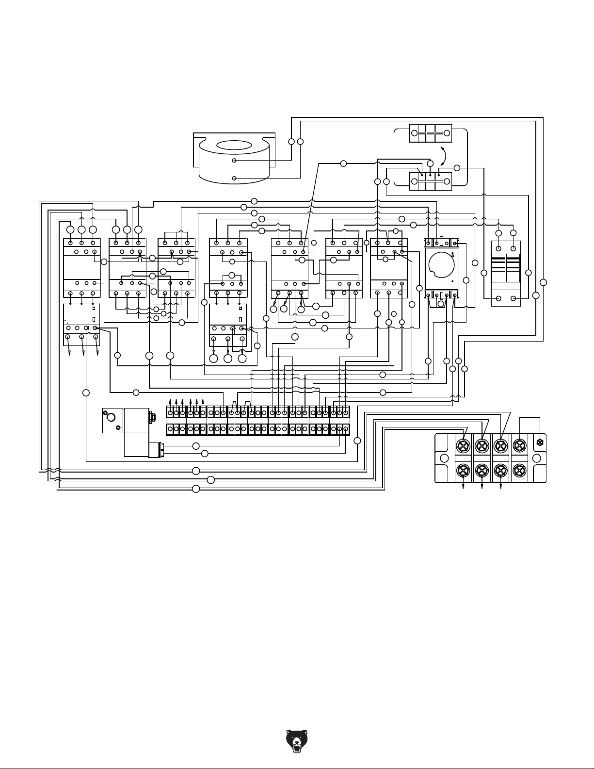
Wiring Box Electrical Diagram (G0581)
220V 3-PH
440V
0VE
3
1
0V
200V
220V
R
S
3
4
675
5
L3
A1
MOTOR
START
DELAY
Y
2
8
2
1
12
3
8
12
15
241214
R
3
1
L
L2
13
NO NC
SANDING MOTOR
CONTACTOR
14
NO
2
T1
THERMAL RELAY
NO
98
97
2
4
T2
T1
U
R
S T
5
L3
21
NC
22 A2
4
T2
NC
96
95
6
T3
V W
6
S T
3
1
L
L2
A1
13
21
NO NC
24 24
SANDING MOTOR
CONTACTOR
14
22 A2
NO
2
T3
4
T2
T1
2
14 15
TRANSFORMER
CURRENT SENSOR
16
18
24
R
S
T
L
13
SANDING
MOTOR
17
CONTACTOR
14
NO
T1
X
3
L2
21
NO NC
22 A2
4
T2
5
1
L3
A1
CONVEYOR
NC
2
6
T3
T1
10
19
5
1
L3
A1
19
12
NC
13
2
6
T3
Z
Y
97
12
13
U1 V 1 W1
L
13
21
NO NC
MOTOR
CONTACTOR
10
14
22 A2
NO
THERMAL RELAY
NO
98
95
2
T1
4
T2
5
3
L3
L2
A1
9
NC
6
4
T3
T2
9
NC
96
6
T3
2
1
2
W2
L
13
TABLE
UP/DOWN
CONTACTOR
T1
3
L2
NO NC
14
4
T2
V2
NO
5
L3
21
NC
22 A2
6
T3
22
2
A1
25
U2
U2
W2
2
3
0
2
3
1
5
3
1
L
L2
13
NO NC
26
TABLE
UP/DOWN
CONTACTOR
14
NO
2
4
T2
T1
V2
2
L3
21
NC
22 A2
6
T3
23
2
A1
L
L2
13
21
NO NC
3
EMERGENCY
BRAKE CONTACTOR
14
22 A2
NO
2
4
T2
T1
6
20
21
NC
6
T3
11
S
R
24
1
11
FUSE FUSE
0
14
15
24
2
SOLENOID VALVE
U1 V 1 U2 V 2 W2 3
W1
2
20
21
T
S
R
3 854
8
6 15
22 23 9 10 1112
13 14
20 21
3
24
ESR
T
L3
L2
L1
-50- H2933/H2934/G0447/G0581 Wide Belt Sander

Wiring Box Components (G0581)
Sanding Motor
Contactor
Conveyor Motor
Contactor
Emergency Brake
Contactor
Two 4 Amp Fuses
Sanding Motor
Start Delay
Transformer
Conveyor Motor
Overload Relay
UP/DOWN Table Motor
Sanding Motor Overload
Relay
H2933/H2934/G0447/G0581 Wide Belt Sander -51-
Contactors
220V/440V
Three-Phase
Power Supply
Junction Block
Amp Meter Current
Sensor
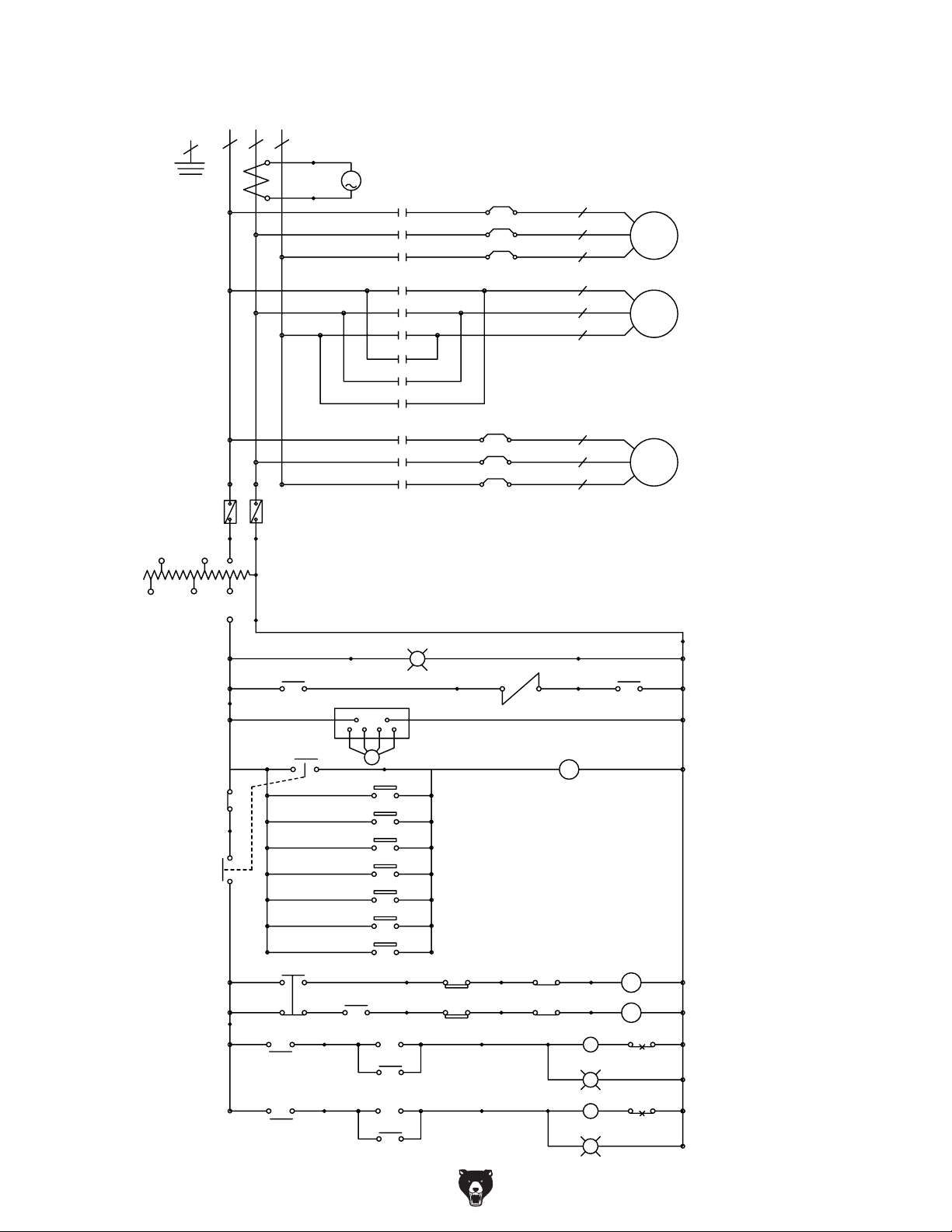
General Electrical Diagram (H2933)
440V
E
FUSE
4A
380V
R
R S
S
1
FUSE
2
0
T
4A
14
15
220V 3-PH
AM
A
M1
U
R
SV
TW
F
U
R
SV
TW
U
R
SV
TW
M3
R
U
S
V
T
W
OL1
OL3
U1
V1
W1
U2
V2
W2
U
V
W
MOTOR
MOTOR
MOTOR
SANDING
BELT
TABLELIFTING
&LOWERING
CONVEYOR
BELT
415V
220V
200V
3
A
6
7
2
A
ab
R
F
M1
GL
2
13
20
21
ab
3
A
Emer genc yBrake
RU VS
PC
LS1
LS2
LS3
LS4
LS5
LS6
LS7
PCR1
PCR2
STOP
8
START
M1
WL
SOL
12
5
EmergencyStop
16
18
LS
LS
17
19
9
A
F
R
OL1
2
POWER SOURCE
BRAKE
EMERGE NCY
BRAKE
TABLELIFTI NG
&LOWERING
SANDINGBELT
STOP
10
START
M3
11
M3
GL
ab
OL3
CONVEYOR BELT
-52- H2933/H2934/G0447/G0581 Wide Belt Sander

General Electrical Diagram (H2934/G0447)
440V
E
415V
380V
220V
R
R
200V
T
S
14
15
AM
A
220V 3-PH
M1
R
S V
OL1
U
U 1
V 1
W1
MOTOR
CONVE Y OR
BE LT
T W
F
R
U
S V
T W
R
R
U
S V
T W
OL3
M 3
R
U
S
S
FUSE
4A
0
0
1
V
T
W
D
U
R
S
V
T
W
U 2
V 2
W2
STAR DELTA
X1
MOTOR
Y1
Z1
MOTOR
M3
R
S
T
T ABL E L I F T I NG
& L OWERI NG
U
SA NDI NG
V
W
BE LT
EM G
STOP
3
3
A
EMERGENCY BRAKE
R U V S
PC
12
W L
SOL
E MG
STOP
3
LS1
A
6
LS2
LS3
LS4
FRONT CONVEYOR
STOP LIMIT SWITCH
LS5
LS6
LS7
PCR1
PCR2
7
STOP
10
16
18
LS
LS
START
17
19
R
F
11
M1
M3
START
9
TR
S
30 31
D
32 33
STOP
8
2
13
20
21
M1
GL
GL
M3
5
D3
S3
A
A
a b
F
R
OL1
O L3
2
PO WE R S OURCE
BRAK E
EMERGENCY
BRAK E
T ABL E L I F T I NG
& LOWERI NG
CONVE Y OR BEL T
SA NDI NG BEL T
H2933/H2934/G0447/G0581 Wide Belt Sander -53-

E
L T
G
D
NG
G
General Electrical Diagram (G0581)
440V
E
415V
FUSE
380V
220V
R
4A
R
S
200V
1
T
220V 3-PH
M1
R
S V
OL1
U
U1
V1
W1
MOTOR
CONVE Y OR
BE LT
T W
F
R
U
S V
T W
R
R
U
S V
T W
OL3
M3
R
S
14
15
A
A M
S
T
D
Z
R
S
X
T
Y
W
U
V
MOTOR
U2
V2
W2
STAR DELTA TYPE
X
Y
Z
MOTOR
S
T ABL E L I F T I
& L OWERI N
SA NDI NG
BE LT
0
EMG STOP
WL
3
A
Emer genc y Brak e
20
SOL
21
A
PO WER SOURC
BRAK E
PC
EMG STOP
3
A
LS1
LS2
6
LS3
FRONT CONVEYOR STOP
LIMI T SWITCH
8
A
Emergency St op
EMERGENCY
BRAK E
LS4
UP
DN
PCR1
STOP
9
4
5
M1
LS
LS
START
22
23
10
R
F
25
26
M1
F
R
O L1
GL
T ABL E L I F T I N
& LOWERI NG
CONVE Y OR BE
7
TR
START
12
18
TR
13
S
D
OL3
SA NDI NG BELT
STOP
11
GL
16 17
TR
S
D
19
24
S
M3
-54- H2933/H2934/G0447/G0581 Wide Belt Sander

Motor Wiring (H2933)
220V-440V 3-PH
W6
W2
U5
U1
U6
U2
V5
V1
V6
V2
W5
W1
220V
SANDING BELT MOTOR
Motor Wiring (H2934/G0447/G0581)
W5
W2
W6
U1
U5
U2
U6
V1
V5
V2
V6
W1
U2
U5
U1
440V
220V-440V 3-PH
V2
V5
V1
220V
W2
W5
W1
U2
U5
U1 V1
V2
V5
440V
CONVEYOR BELT MOTOR
AND
TABLE UP/DOWN MOTOR
W2
W5
W1
W6
W2
Z X Y
U5
U1
U V W
U6
U2
V5
V1
V6
V2
W5
W1
220V
SANDING BELT MOTOR
W5
W2
W6
Z X Y
U1
U V W
U5 V5
U2
U6
V1
440V
V2
V6
W1
( S T A R D E L T A )
U2
U5
U1
U1
V2
V5
V1
V1
W2
W5
W1
W1
U2
U5
U1 V1
U1
220V
CONVEYOR BELT MOTOR
U2
V2
220V
W2
U2
V2
V5
V1
440V
V2
440V
W2
W5
W1
W1
W2
TABLE UP/DOWN MOTOR
H2933/H2934/G0447/G0581 Wide Belt Sander -55-

Tool Box and Accessories Diagram
0000 Series Parts
7-1
2
1
4
7-2
6
5
3
8
9
12
11
10
13
-56- H2933/H2934/G0447/G0581 Wide Belt Sander

Tool Box and Accessories Parts List
REF PART # DESCRIPTION REF PART # DESCRIPTION
1 PH29330001 PLATEN REMOVAL TOOL 7-1 P04470007-1 SANDPAPER #100 (37" X 75") (G0447)
2 PH29330002 CERAMIC LIMIT SWITCH TIP 7-1 P05810007-1 SANDPAPER #100 (43" X 60") (G0581)
3 PH29330003 TOOL BOX 7-2 PH29330007-2 SANDPAPER #180 (25" X 60") (H2933)
4 PH29330004 25" FELT PLATEN PAD (H2933) 7-2 PH29340007-2 SANDPAPER #180 (37" X 60") (H2934)
4 PH2934004 37-3/4" PLATEN FELT (H2934/G0447) 7-2 P04470007-2 SANDPAPER #180 (37" X 75") (G0447)
4 P058100004 44" PLATEN FELT (G0581) 7-2 P05810007-2 SANDPAPER #180 (43" X 60") (G0581)
5 PH29330005 GRAPHITE 25" X 3.54" (H2933) 8 PH29330008 #2 PHILLIPS SCREWDRIVER
9 PH29330009 SCREWDRIVER FLAT #2
10 PH29330010 WRENCH 8 X 10
5 P05810005 GRAPHITE 44" X 3.54" (G0581) 11 PH29330011 WRENCH 12 X 14
6 PH29330006 DOOR KEY 12 PH29330012 WRENCH 17 X 19
7-1 PH29330007-1 SANDPAPER #100 (25" X 60") (H2933) 13 PH29330013 HEX WRENCH SET
7-1 PH29340007-1 SANDPAPER #100 (37" X 60") (H2934)
GRAPHITE 37-3/4" X 3.54"
(H2934/G0447)
PH29340005
5
H2933/H2934/G0447/G0581 Wide Belt Sander -57-

Sanding Motor System Diagram
1000 Series Parts
133
128
129
125
126
109
107
106
102
124
104
106
101
108
105
212
106
132
209
103
114
210
115
116
127
104
211
205
206
119
301
208
312
306
113
213
202
303
304
308
123
122
203
302
313
201
305
112
311
111
310
121
307
301-1
109-2
118
110
109-1
117
-58- H2933/H2934/G0447/G0581 Wide Belt Sander

Sanding Motor System Parts List
REF PART # DESCRIPTION REF PART # DESCRIPTION
101 PH29331101
MACHINE FRAME (H2933)
118 PH29341118
PULLEY BUSHING (H2934/G0447)
101 PH29341101
MACHINE FRAME (H2934/G0447)
118 P05811118
PULLEY BUSHING (G0581)
101 P05811101
MACHINE FRAME (G0581)
119 PH29331119
V-BELT A-50 4L500
102 PH29331102
MOTOR BASE (H2933)
121 PH29331121
BRAKE BRACKET
102 PH29341102
MOTOR BASE (H2934/G0447)
122 PH29331122
FLAT WASHER 3/8
102 P05811102
MOTOR BASE (G0581)
123 PH29331123
HEX BOLT 3/8-16 X 3/4
103 PH29331103
MOTOR BASE HINGE (H2933)
124 PH29331124
FLAT HEAD NUT
125 PH29331125
CAP SCREW 1/4-20 X 3/4
126 PH29331126
LIMIT SWITCH
103 P05811103
MOTOR BASE HINGE (G0581)
127 PH29331127
LIMIT SWITCH PLATE
104 PH29331104
HEX NUT 1/2-12
128 PH29331128
HEX BOLT 1/4-20 X 1/2
105 PH29331105
MOTOR BASE ADJUSTMENT ROD
129 PH29331129
FLAT WASHER 1/4
106 PH29331106
LOCK WASHER 1/2
132 PH29331132
FLAT HD SCR M6-1 X 25
107 PH29331107
HEX BOLT 1/2-12 X 1-1/2
133 PH29331133
LOCK WASHER 1/4
108 PH29331108
FLAT WASHER 1/2
201 PH29331201
IDLE WHEEL ADJ BRACKET
202 PH29331202
LOCK WASHER 3/4
203 PH29331203
HEX NUT 1/2-12
205 PH29331205
HEX BOLT 3/8-16 X 3-1/2
206 PH29331206
HEX NUT 3/8-16
208 PH29331208
IDLE WHEEL SHAFT
209 PH29331209
BALL BEARING 6305ZZ
109-1 PH29331109-1
MOTOR FAN (H2933)
210 PH29331210
PULLEY
109-1 PH29341109-1
MOTOR FAN (H2934/G0447)
211 PH29331211
BALL BEARING 6206ZZ
109-1 P05811109-1
MOTOR FAN (G0581)
212 PH29331212
EXT RETAINING RING 25MM
109-2 PH29331109-2
MOTOR FAN COVER (H2933)
213 PH29331213
V-BELT A-40 4L400
301 PH29331301
BRAKE BRACKET
301-1 PH29331301-1
BREAK BRACKET FRONT GUARD
109-2 P05811109-2
MOTOR FAN COVER (G0581)
302 PH29331302
BRAKE LINING SET
110 PH29331110
PULLEY (H2933)
303 PH29331303
BRAKE ARBOR
110 PH29341110
PULLEY (H2934/G0447)
304 PH29331304
BRAKE COMPRESSION SPRING
110 P05811110
PULLEY (G0581)
305 PH29331305
BRAKE INSIDE PIECE
111 PH29331111
CAP SCREW 5/16-18 X 1-1/4
306 PH29331306
FLAT HD SCR 1/4-20 X 5/8
112 PH29331112
LOCK WASHER 5/16
307 PH29331307
BRAKE PIN
113 PH29331113
KEY 12 X 8 X105
308 PH29331308
CAP SCREW 10-24 X 5/8
114 PH29331114
HEX BOLT 5/16-18 X 1
310 PH29331310
LOCK WASHER 3/8
115 PH29331115
LOCK WASHER 5/16
311 PH29331311
HEX NUT 3/8-16
116 PH29331116
ROTOR
312 PH29331312
CAP SCREW 1/4-20 X 1/2
117 PH29331117
V-BELT B-76 5L760
313 PH29331313
BRAKE GASKET
118 PH29331118
PULLEY BUSHING (H2933)
MOTOR 15HP 220V/440V 3PH
(H2933)
PH29331109
109
109
109
PH29341109
P05811109
MOTOR FAN COVER (H2934/G0447)
PH29341109-2
109-2
MOTOR BASE HINGE
(H2934/G0447)
PH29341103
103
MOTOR 20HP 220V/440V 3PH
(H2934/G0447)
MOTOR 25HP 220V/440V 3PH
(G0581)
H2933/H2934/G0447/G0581 Wide Belt Sander -59-

Table Lift System Diagram
2000 Series Parts
101
202
203
103
104
102
331-1
326
325
331
323
327
328
326
324
111
331-2
322
332
333
109
110
201
408
315
204
409
402
316
410
404
403
337
341
317
206
407
406
406
336
401
405
334
308
338
324
314
307
301
105
335
309
107
106
312
108
340
306
307
318
313
319
310
320
311
321
303
339
302
304
303
305
-60- H2933/H2934/G0447/G0581 Wide Belt Sander

Table Lift System Parts List
REF PART # DESCRIPTION REF PART # DESCRIPTION
101 PH29332101
ELEVATION SCREW
318 PH29332318
LOCK WASHER 5/16
102 PH29332102
HEX BOLT 5/16-18 X 1
319 PH29332319
HEX BOLT 5/16-18 X 3/4
103 PH29332103
FLAT WASHER 5/16
320 PH29332320
SET SCREW 1/4-20 X 1/2
104 PH29332104
LOCK WASHER 5/16
321 PH29332321
HAND WHEEL
105 PH29332105
LOCK WASHER 3/8
322 PH29332322
MOTOR BASE
106 PH29332106
HEX BOLT 3/8-16 X 1
323 PH29332323
HEX BOLT 1/4-20 X 1
107 PH29332107
ELEVATION SLIDE
324 PH29332324
LOCK WASHER 1/4
108 PH29332108
DUST BOOT
325 PH29332325
ADJUSTMENT ROD
109 PH29332109
HEX BOLT 5/16-18 X 3/4
326 PH29332326
FLAT WASHER 1/2
110 PH29332110
LOCK WASHER 5/16
327 PH29332327
HEX NUT 1/2-12
111 PH29332111
CHAIN (H2933)
328 PH29332328
LOCK WASHER 1/2
111 PH29342111
CHAIN (H2934/G0447)
111 P05812111
CHAIN (G0581)
201 PH29332201
NUT HOUSING
331-1 PH29332331-1
FAN COVER (ALL MODELS)
202 PH29332202
NUT
331-2 PH29332331-2
FAN (ALL MODELS)
203 PH29332203
THRUST BEARING 51107
332 PH29332332
HEX NUT 1/4-20
204 PH29332204
EXT RETAINING RING 35MM
333 PH29332333
HEX BOLT 1/2-12 X 4-1/2
206 PH29332206
SPROCKET WHEEL
334 PH29332334
PROXIMITY SWITCH PLATE
301 PH29332301
ELEVATION GEAR BOX
335 PH29332335
HEX BOLT 1/4-20 X 1/2
302 PH29332302
WORM GEAR
336 PH29332336
PROXIMITY SWITCH
303 PH29332303
BALL BEARING 6005ZZ
337 PH29332337
SPECIAL SCREW M3-.5 X 40
304 PH29332304
BEARING CAP
338 PH29332338
HEX NUT M3-.5
305 PH29332305
CAP SCREW 1/4-20 X 3/4
339 PH29332339
KEY 5/16 X 5/16 X 3/4
306 PH29332306
WORM SHAFT
340 PH29332340
KEY 4 X 4 X 20
307 PH29332307
BALL BEARING 6002ZZ
341 PH29332341
KEY 4 X 4 X 16
308 PH29332308
BEARING CAP
401 PH29332401
SPROCKET WHEEL ADJUSTOR
309 PH29332309
CAP SCREW 10-24 x 3/4
402 PH29332402
SPROCKET WHEEL SHAFT
310 PH29332310
BEARING CAP
403 PH29332403
BALL BEARING 6003ZZ
311 PH29332311
CAP SCREW 1/4-20 X 5/8
404 PH29332404
ADJUSTMENT SPROCKET
312 PH29332312
SPROCKET WHEEL
405 PH29332405
ADJUSTMENT ROD
313 PH29332313
SET SCREW 1/4-20 X 1/2
406 PH29332406
FLAT WASHER 3/8
314 PH29332314
PULLEY
407 PH29332407
HEX NUT 3/8-16
315 PH29332315
V-BELT A-36 4L360
408 PH29332408
HEX NUT 5/16-18
316 PH29332316
PULLEY
409 PH29332409
LOCK WASHER 5/16
317 PH29332317
SET SCREW 1/4-20 X 1/2
410 PH29332410
HEX BOLT 5/16-18 X 3/4
MOTOR 1/4HP 220V/440V 3PH (ALL
MODELS)
PH293323331
331
H2933/H2934/G0447/G0581 Wide Belt Sander -61-

Conveyor System Diagram
3000 Series Parts
129
113
115
130
114
121
117
112
116
113
107
118
108
126
119
128
106
113
105
124
127
123
103
110
123-2
123-1
140
102
133
142
143
202
141
206
205
201
144
203
204
137
135
136
138
131
101
132
113
117
104
109
111
121
120
-62- H2933/H2934/G0447/G0581 Wide Belt Sander

Conveyor System Parts List
CAP SCREW 1/4-20 X 1-1/2
CONVEYOR TABLE
MOTOR FAN (H2933, H2934,
OUTFEED ROLLER
MOTOR 1HP 220V/440V 3PH
MOTOR 2HP 220V/440V 3PH
MOTOR FAN COVER (H2933,
EMGNCY BRAKE PUSH-PLATE
EMGNCY BRAKE PUSH-PLATE
EMGNCY BRAKE PUSH-PLATE
REF PART # DESCRIPTION REF PART # DESCRIPTION
101 PH29333101
PH29343101101 123-2
101 P05813101
102 PH29333102
102 PH29343102
102 P05813102
103 PH29333103
104 PH29333104
105 PH29333105
106 PH29333106
107 PH29333107
PH29343107107
107 P05813107
108 PH29333108
109 PH29333109
110 PH29333110
111 PH29333111
112 PH29333112
113 PH29333113
114 PH29333114
115 PH29333115
116 PH29333116
117 PH29333117
118 PH29333118
119 PH29333119
120 PH29333120
121 PH29333121
123 PH29333123
123 P05813123
123-1 PH29333123-1
CONVEYOR TABLE (H2933)
(H2934/G0447)
CONVEYOR TABLE (G0581)
CONVEYOR BELT (H2933)
CONVEYOR BELT (H2934/G0447)
CONVEYOR BELT (G0581)
REDUCER FIX PLATE
CUSHION
LOCK WASHER 3/8
HEX BOLT 3/8-16 X 1
OUTFEED ROLLER (H2933)
(H2934/G0447)
OUTFEED ROLLER (G0581)
BEARING UCF206
GEARBOX
BREATHER
PLUG
BALL BEARING UCF205
LOCK WASHER 3/8
HEX BOLT 3/8-16 X 1-1/4
BEARING CAP
DRIVEN PULLEY
HEX BOLT 3/8-16 X 1-1/2
DRIVING PULLEY
KEY 7 X 7 X 55
HEX BOLT M8-1.25 X 25
LOCK WASHER 8MM
(H2933, H2934, G0447)
(G0581)
H2934, G0447)
123-1 P05813123-1
PH29333123-2
123-2 P05813123-2
124 PH29333124
126 PH29333126
127 PH29333127
128 PH29333128
129 PH29333129
130 PH29333130
131 PH29333131
132 PH29333132
133 PH29333133
135 PH29333135
136 PH29333136
137 PH29333137
138 PH29333138
PH29333140140
140 PH29343140
P05813140140
141 PH29333141
142 PH29333142
143 PH29333143
144 PH29333144
201 PH29333201
202 PH29333202
202 PH29343202
202 P05813202
203 PH29333203
204 PH29333204
205 PH29333205
206 PH29333206
MOTOR FAN COVER (G0581)
G0447)
MOTOR FAN (G0581)
LOCK WASHER 5/8
TIMING BELT 1422V-290
CAP SCREW M10-1.5 X 25
BASE PLATE
VARIABLE SPEED UNIT COVER
HEX BOLT M8-1.25 X 20
INFEED ROLLER BRACKET
CAP SCREW 10-24 x 3/4
INFEED ROLLER BRACKET
CONVEYOR POSITION WHEEL
CAP SCREW 5/16-18 X 2
LOCK WASHER 5/16
HEX NUT 5/16-18
(H2933)
(H2934/G0447)
(G0581)
PHLP HD SCR 1/4-20 X 1/2
LIMIT SWITCH
PHLP HD SCR 10-24 x 1 1/2
HEX BOLT 1/2-12 X 3
INFEED ROLLER SHAFT
INFEED ROLLER (H2933)
INFEED ROLLER (H2934/G0447)
INFEED ROLLER (G0581)
BALL BEARING 6206ZZ
EXT RETAINING RING 30MM
ELEVATION LIMITER
H2933/H2934/G0447/G0581 Wide Belt Sander -63-

Feed, Drum, and Pressure Roller Diagram
4000 Series Parts
105
104
101
103
106
107
204
205
102
203
109
108
201
H2933
H2934
G0581
102
204
203
202
301
205
103
107
302
303
102
204
201
203
308
G0447
204
201
203
302
202
311
107
203
204
102
312
205
202
203
313
304
205
204
103
301
107
302
103
107
301
302
303
307
309
310
306
205
201
202
-64- H2933/H2934/G0447/G0581 Wide Belt Sander

Feed, Drum, and Pressure Roller Parts List
REF PART # DESCRIPTION REF PART # DESCRIPTION
101 PH29334101
PISTON SLIDERAIL
204 PH29334204
SHAFT BEARING COLLAR
205 PH29334205
SET SCREW 1/4-20 X 1/2
103 PH29334103
COMPRESSION SPRING
104 PH29334104
ROD 10 X 35
301 P04474301
GUIDE STUD (G0447)
105 PH29334105
SET SCREW 1/4-20 X 1/2
302 PH29334302
PISTON BRACKET MIDDLE
106 PH29334106
HEX BOLT 5/16-18 X 1-1/2
303 PH29334303
ROLL PIN 3 X 27
107 PH29334107
HEX NUT 5/16-18
304 P04474304 RR PISTON BRACKET (G0447)
108 PH29334108
HEX BOLT 5/16-18 X 1-1/4
306 P04474306 LF PISTON BRACKET (G0447)
109 PH29334109
LOCK WASHER 5/16
201 PH29334201
PISTON ROLLER SHAFT (H2933)
308 P04474308 LR PISTON BRACKET (G0447)
309 PH29334309
LOCK WASHER 5/16
201 P05814201
PISTON ROLLER SHAFT (G0581)
310 PH29334310
HEX BOLT 5/16-18 X 1-1/4
202 PH29334202
PISTON ROLLER (H2933)
311 P04474311 REAR DEFLECTOR (G0447)
202 PH29344202
PISTON ROLLER (H2934/G0447)
312 P04474312 MIDDLE DEFLECTOR (G0447)
202 P05814202
PISTON ROLLER (G0581)
313 P04474313 FRONT DEFLECTOR (G0447)
203 PH29334203
BALL BEARING 6003ZZ
PISTON BRACKET OUTER
(H2933/H2934/G0581)
PH29334102
102
PISTON ROLLER SHAFT
(H2934/G0447)
PH29344201
201
301
PH29334301
GUIDE STUD (H2933/H2934/G0581)
L MIDDLE PISTON BRACKET
(G0447)
P04474307
307
H2933/H2934/G0447/G0581 Wide Belt Sander -65-

Sanding Drum and Platen Diagram
5000 Series Parts
112
411
114
410
114
112
205
409
113
408
320
323
119
319
109
206
318
317
407
402
205
201
102
211
114
206
304
303
302
110
111
112
301
113
119
308
305
109
202
401
306
116
110
111
104
311
115
310
309
315
312
313
314
307
403
203
405
316
321
322
104
322
101
115
406
321
107
103
203
105
108
204
114
203
107
108
106
117
120
417
118
-66- H2933/H2934/G0447/G0581 Wide Belt Sander

Sanding Drum and Platen Parts List
REF PART # DESCRIPTION REF PART # DESCRIPTION
101 PH29335101
102 PH29335102
102 PH29345102
102 P05815102
103 PH29335103
104 PH29335104
105 PH29335105
106 PH29335106
107 PH29335107
108 PH29335108
109 PH29335109
110 PH29335110
111 PH29335111
112 PH29335112
113 PH29335113
114 PH29335114
115 PH29335115
116 PH29335116
117 PH29335117
118 PH29335118
119 PH29335119
120 PH29335120 PHLP HD SCR 1/4-20 X 3/8 312 PH29335312
201 PH29335201
202 PH29335202
202 PH29345202
202 P05815202
203 PH29335203
204 PH29335204
205 PH29335205
206 PH29335206
211 PH29335211
301 PH29335301 25" GRAPHITE BRACKET MALE
PH29345301301
301 P05815301 44" GRAPHITE BRACKET MALE
PH29335302302
302 PH29345302 37-1/2" GRAPHITE BRACKET
P05815302302
303 PH29335303
PH29345303303
303 P05815303
BEARING HOUSING
RUBBER ROLLER (H2933)
RUBBER ROLLER (H2934/G0447)
RUBBER ROLLER (G0581)
FASTENING TUBE
BEARING UCC206
PULLEY
CAP SCREW 5/16-18 X 1-1/4
KEY 5/16 X 5/16 X 1 3/16
LOCK WASHER 5/16
BALL BEARING 6205ZZ
LOCK WASHER 1/2
CAP SCREW 1/2-12 X 1-1/2
CAP SCREW 1/4-20 X 1/2
BEARING CAP
GREASE FITTING W/CAP
GREASE FITTING W/CAP
PLUG
PULLEY COVER
PHLP HD SCR 1/4-20 X 1/2
SPANNER NUT
BEARING HOUSING
STEEL ROLLER (H2933)
STEEL ROLLER (H2934/G0447)
STEEL ROLLER (G0581)
SPECIAL SET SCREW M6-.75 X 6
BEARING UCC205
HANDLE
SPECIAL SCREW
BEARING BRACKET PAD (H2933)
(H2933)
37-1/2" GRAPHITE BRACKET MALE
(H2934/G0447)
(G0581)
25" GRAPHITE BRACKET FEMALE
(H2933)
FEMALE (H2934/G0447)
44" GRAPHITE BRACKET FEMALE
(G0581)
25" FELT PLATEN PAD (H2933)
37-1/2" FELT PLATEN PAD
(H2934/G0447)
44" FELT PLATEN PAD (G0581)
304 PH29335304
PH29345304304
304 P05815304
305 PH29335305
306 PH29335306
PH29345306306
306 P05815306
307 PH29335307
PH29335308
308
PH29345308
308
P05815308308
309 PH29335309
310 PH29335310
311 PH29335311
313 PH29335313
314 PH29335314
315 PH29335315
316 PH29335316
317 PH29335317
318 PH29335318
319 PH29335319
320 PH29335320
321 PH29335321
322 PH29335322
323 PH29335323
401 PH29335401
402 PH29335402
402 PH29345402
402 P05815402
403 PH29335403
405 PH29335405
406 PH29335406
407 PH29335407
408 PH29335408
409 PH29335409
410 PH29335410
411 PH29335411
417 PH29335417
GRAPHITE 25" x 3.54" (H2933)
GRAPHITE 37-3/4" x 3.54"
(H2934/G0447)
GRAPHITE 44" x 3.54" (G0581)
PHLP HD SCR 10-24 X 1/2
25" GRAPHITE PRESSURE PLATE
(H2933)
37-1/2" GRAPHITE PRESSURE
PLATE (H2934/G0447)
44" GRAPHITE PRESSURE PLATE
(G0581)
GRAPHITE BRACKET BASE
GRAPHITE BRACKET SHAFT (H2933)
GRAPHITE BRACKET SHAFT
(H2934/G0447)
GRAPHITE BRACKET SHAFT (G0581)
LOCK COLLAR
SET SCREW 1/4-20 X 3/8
KEY 1/4-20 X 25
COMPRESSION SPRING
HOUSING
GRAPHITE BRACKET SHAFT
CAP SCREW 3/8-16 X 3/4
FLAT WASHER 3/8
FLAT WASHER 3/8
HANDLE
SET SCREW 5/16-18 X 1/2
ADJUSTMENT RING
HEX BOLT 5/16-18 X 1
FLAT WASHER 5/16
HANDLE
BEARING HOUSING
RUBBER ROLLER (H2933)
RUBBER ROLLER (H2934/G0447)
RUBBER ROLLER (G0581)
FASTENING TUBE
PULLEY
CAP SCREW 5/16-18 X 1-1/4
BEARING HOUSING
BEARING BRACKET PAD
BALL BEARING 6206ZZ
SPANNER CAP
BEARING CAP
PULLEY COVER
H2933/H2934/G0447/G0581 Wide Belt Sander -67-

Upper Roller System Diagram
104-1
301
108
105
104
202
208
206
207
320
106
205
302
305
204
203
111
304
310
116-1
107
201
304
115
131
303
6000 Series Parts
202
113
128
111
116-2
112
116
115-1
117
116-1
131
119
115
130
130
131
132
118
109
203
129
306
307
204
120
205
208
311
308
103
317
309
315
124
312
121
127
135
313
316
314
122
133
126
123
134
136
125
318
139
131
319
101-1
102
102
101
108
103-1
104
104-1
101-1
112
110
113
102
202
111
101
201
137
142
141
140
139
103
138
G0581
103-1
-68- H2933/H2934/G0447/G0581 Wide Belt Sander

Upper Roller System Parts List
REF PART # DESCRIPTION REF PART # DESCRIPTION
101 PH29336101
SQUARE FRAME REAR (H2933)
127 PH29336127
PHLP HD SCR M4-.7 X 12
101 PH29346101
SQUARE FRAME REAR (H2934)
128 PH29336128
SHUTDOWN BRACKET
101 P04476101
SQUARE FRAME REAR (G0447)
129 PH29336129
HEX NUT 3/8-24
101 P05816101
SQUARE FRAME REAR (G0581)
130 PH29336130
FLAT WASHER 5/16
101-1 PH29336101-1
SQUARE FRAME FRONT (H2933)
131 PH29336131
LOCK WASHER 5/16
101-1 PH29346101-1
SQUARE FRAME FRONT (H2934)
132 PH29336132
HEX BOLT 5/16-18 X 1/2
101-1 P04476101-1
SQUARE FRAME FRONT (G0447)
133 PH29336133
PHLP HD SCR 10-24 X 3/4
101-1 P05816101-1
SQUARE FRAME FRONT (G0581)
134 PH29336134
HEX NUT 10-24
103 PH29336103
FRAME SEAL RIGHT (H2933)
135 PH29336135
CONNECTOR OF OIL CAP
103 PH29346103
FRAME SEAL RIGHT (H2934)
136 PH29336136
SHAFT OF OIL CAP
103 P04476103
FRAME SEAL RIGHT (G0447)
137 P05816137 BRACKET (G0581)
103 P05816103
FRAME SEAL RIGHT (G0581)
138 P05816138 BRACKET (G0581)
103-1 PH29336103-1
FRAME SEAL FRONT (H2933)
139 PH29336139
CAP SCREW 5/16-18 X 1-1/2
103-1 PH29346103-1
FRAME SEAL FRONT (H2934)
140 PH29336140
CAP SCREW 1/2-12 X 1-1/2
103-1 P04476103-1
FRAME SEAL FRONT (G0447)
141 PH29336141
LOCK WASHER 1/2
103-1 P05816103-1
FRAME SEAL FRONT (G0581)
142 PH29336142
HEX BOLT 1/2-12 X 1
104 PH29336104
FRAME SEAL LEFT (H2933)
201 PH29336201
BRACKET (H2933, H2934, G0447)
104 PH29346104
FRAME SEAL LEFT (H2934)
201 P05816201
BRACKET (G0581)
104 P04476104
FRAME SEAL LEFT (G0447)
202 PH29336202
UPPER ROLLER (H2933)
104 P05816104
FRAME SEAL LEFT (G0581)
202 PH29346202
UPPER ROLLER (H2934/G0447)
104-1 PH29336104-1
FRAME SEAL FRNT LFT (H2933)
202 P05816202
UPPER ROLLER (G0581)
104-1 PH29346104-1
FRAME SEAL FRNT LFT (H2934)
203 PH29336203
UPPER ROLLER BRACKET
104-1 P04476104-1
FRAME SEAL FRNT LFT (G0447)
204 PH29336204
BEARING UCC205
104-1 P05816104-1
FRAME SEAL FRNT LFT (G0581)
205 PH29336205
SET SCREW M6-1 X 6
105 PH29336105
FLAT HD SCR 1/4-20 X 1/2
206 PH29336206
CAP SCREW 10-24 x 3/4
106 PH29336106
LOCK WASHER 3/8
207 PH29336207
LOCK WASHER 3/8
107 PH29336107
HEX BOLT 3/8-16 X 1
208 PH29336208
GREASE FITTING W/DUST CAP
108 PH29336108
LOCK WASHER 1/2
301 PH29336301
KNOB (H9233, H2934, G0447)
109 PH29336109
HEX BOLT 1/2-12 X 1
301 P05816301
KNOB (G0581)
110 PH29336110
PHLP HD SCR 1/4-20 X 1/2
302 PH29336302
ECCENTRIC ROD
111 PH29336111
CAP SCREW 5/16-18 X 3/4
303 PH29336303
CAP SCREW 1/2-12 X 3-1/2
112 PH29336112
HEX BOLT 5/16-18 X 1
304 PH29336304
FLAT WASHER 1/2
113 PH29336113
AIR CYLINDER
305 PH29336305
ECCENTRIC
115 PH29336115
LIMIT SWITCH W/CERAMIC TIP
306 PH29336306
CLEVIS ASSEMBLY
115-1 PH29336115-1
CERAMIC TIP
307 PH29336307
EXT RETAINING RING 15MM
116 PH29336116
LIMIT SWITCH W/PLASTIC TIP
308 PH29336308
HEX NUT M10-1.5 (LH)
116-1 PH29336116-1
PLASTIC TIP
309 PH29336309
SHAFT OF AIR CYLINDER
116-2 PH293361116-2
LIMIT SWITCH POST
310 PH29336310
HEX NUT 1/2-12
117 PH29336117
LIMIT SWITCH HOLDER
311 PH29336311
BOTTOM COVER
118 PH29336118
AIR SENSOR NOZZLE FEMALE
312 PH29336312
COMPRESSION SPRING
119 PH29336119
AIR FORK
313 PH29336313
ALUMINUM PLATE
120 PH29336120
AIR SENSOR NOZZLE MALE
314 PH29336314
FLAT HD SCR M6-1 X 12
121 PH29336121
THROTTLE VALVE
315 PH29336315
PLATE
122 PH29336122
THROTTLE VALVE BASE
316 PH29336316
TOP COVER
123 PH29336123
PLATE
317 PH29336317
HEX NUT 10-24
124 PH29336124
HOUSING ASSEMBLY
318 PH29336318
PHLP HD SCR 10-24 X 3/4
125 PH29336125
OIL CAP
319 PH29336319
AIR CYLINDER BASE
126 PH29336126
ALUMINUM PLATE
320 PH29336320
ECCENTRIC SHAFT FRAME
H2933/H2934/G0447/G0581 Wide Belt Sander -69-

Cabinet Assembly Diagram
7000 Series Parts
102
104
103
113
112
114
110
108
115
101
107
106
105
109-1
109
111
-70- H2933/H2934/G0447/G0581 Wide Belt Sander

Cabinet Assembly Parts List
REF PART # DESCRIPTION REF PART # DESCRIPTION
101 PH29337101
UPPER FRAME COVER (H2933)
101 PH29347101
UPPER FRAME COVER (H2934)
101 P04477101
UPPER FRAME COVER (G0447)
101 P05817101
UPPER FRAME COVER (G0581)
102 PH29337102
DUST PORT 4"
103 PH29337103
PHLP HD SCR M6-1 X 12
104 PH29337104
LEFT ACCESS PANEL (H2933)
104 PH29347104
LEFT ACCESS PANEL (H2934)
104 P04477104
LEFT ACCESS PANEL (G0447)
104 P05817104
LEFT ACCESS PANEL (G0581)
105 PH29337105
RIGHT ACCESS PANEL (H2933)
110 PH29337110
FLAT HD SCR 1/4-20 X 1/2
105 PH29347105
RIGHT ACCESS PANEL (H2934)
105 P04477105
RIGHT ACCESS PANEL (G0447)
105 P05817105
RIGHT ACCESS PANEL (G0581)
106 PH29337106
DOOR LOCK
107 PH29337107
HEX BOLT 5/16-18 X 3/4
108 PH29337108
FLAT WASHER 5/16
112 PH29337112
FLAT WASHER 1/4
113 PH29337113
PHLP HD SCR M6-1 X 12
114 PH29337114
HEX BOLT 1/4-20 X 3/4
115 PH29337115
STANDOFF BRACKET
109
P04477109
RIGHT DOOR, LOWER FRAME
(G0447)
109
PH29347109
RIGHT DOOR, LOWER FRAME
(H2934)
RIGHT DOOR, LOWER FRAME
(H2933)
PH29337109
109
109
P05817109
RIGHT DOOR, LOWER FRAME
(G0581)
LEFT DOOR, LOWER FRAME (H2933)
LEFT DOOR, LOWER FRAME (H2934)
LEFT DOOR, LOWER FRAME
(G0447)
LEFT DOOR, LOWER FRAME
(G0581)
P05817109-1
P04477109-1
PH29347109-1
PH29337109-1
109-1
109-1
109-1
109-1
111
PH29337111
FRONT PROTECTION PLATE (H2933)
FRONT PROTECTION PLATE (H2934)
PH29347111
111
111
111
P04477111
P05817111
FRONT PROTECTION PLATE
(G0447)
FRONT PROTECTION PLATE
(G0581)
H2933/H2934/G0447/G0581 Wide Belt Sander -71-

Main Electrical Panel and Controls Diagram
8000 Series Parts
107
128
130
H2933
H2934
G0447
G0581
111
108
H2933
126A
133
129
131
109
115
110
103
H2933
H2934
G0447
G0581
102
101
122
124
122
123
119
120
121
112
134 (440V)
H2934
G0447
112
134 (440V)
114
135 (440V)
111
127
114
135 (440V)
115-1
118
118
109
117
115
105
110
113
132
116
106
113
116
104
132
104
G0581
111
112
134 (440V)
114
135 (440V)
111
118
115-1
115
132
110
109
104
116
127
113
-72- H2933/H2934/G0447/G0581 Wide Belt Sander

Main Electrical Panel and Controls Parts List
H2933 440V Conversion Kit
PH29339139V2
PH29338134V2
H2934 440V Conversion Kit
G0581 440V Conversion Kit
G0447 440V Conversion Kit
REF PART # DESCRIPTION REF PART # DESCRIPTION
101
PH29348101
101
101 P05818101 ELECTRICAL CONTROL BOX
102 PH29338102
103 PH29338103
103 PH29348103
103 P05818103
104 PH29338104
104 PH29348104
104 P05818104
105 PH29338105
106 PH29338106
107 PH29338107
108 PH29338108
109 PH29338109
110 PH29338110
111 PH29338111
111 PH29348111 CONTACTOR LC1-D368
PH29338112112
112 PH29348112 RELAY LR3-D326 220V (23-32A)
P05818112112
113 PH29338113
114 PH29338114 RELAY LR3-086 220V (2.5-4A)
ELECTRICAL CONTROL BOX (H2933)PH29338101
ELECTRICAL CONTROL BOX
(H2934/G0447)
(G0581)
HINGE
DOOR (H2933)
DOOR (H2934/G0447)
DOOR (G0581)
BASE PLATE (H2933)
BASE PLATE (H2934/G0447)
BASE PLATE (G0581)
HEX NUT 1/4-20
LOCK WASHER 1/4
CONTROL PANEL
PHLP HD SCR M4-.7 X 8
CURRENT SENSOR
TRANSFORMER
CONTACTOR LC1-D40 (H2933)
(H2934/G0447/G0581)
RELAY LR3-D3355 220V (3040A)(H2933)
(H2934/G0447)
RELAY LR3D-D356 220V (30-38A)
(G0581)
FUSE TE10.3 X 38 & 500V/4Ax2
(H2933/H2934/G0447)
P05818114114
115 PH29338115
PH29348115-1115-1
115-1 P05818115-1
116 PH29338116
116 PH29348116 POWER WIRE TERMINAL
116 P05818116
118 PH29338118
119 PH29338119
120 PH29338120
121 PH29338121
122 PH29338122
123 PH29338123
124 PH29338124
126A PH29338126A
127
PH29348127
127
P05818127
128 PH29338128
129 PH29338129
130 PH29338130
131 PH29338131
132 PH29338132
P05818132132
133 PH29338133
RELAY LR3D-126 220V (2.5-4A)
(G0581)
CONTACTOR LC1-D096 (H2933)
CONTACTOR LC1-D256
(H2934/G0447)
CONTACTOR LC1-D098 (G0581)
POWER WIRE TERMINAL (H2933)
(H2934/G0447)
POWER WIRE TERMINAL (G0581)
TERMINAL PLATE
FLAT WASHER 1/4
LOCK WASHER 1/4
HEX BOLT 1/4-20 X 1/2
PU CONNECTOR 1/2"
PU CONNECTOR 3/4"
CABLE CONNECTOR 1"
DIGITAL AMP METER N/S
START DELAY LADS2
(H2934/G0447)
START DELAY TRD-N (STON
BRAND) (G0581)
START SWITCH
STOP SWITCH
POWER INDICATION LIGHT
EMERCENGY STOP SWITCH
WIRE COLUMN (G0581)
WIRE COLUMN
(H2933/H2934/G0447)
COMPUTER
139 PH29349139 440V CONVERSION KIT
134 PH29348134 OL RELAY SCHN LR3D21 12-18A
135 PH29338135 OL RELAY SCHN LR3D07 1.6-2.5A
139 P05819139 440V CONVERSION KIT
134 PH29348134 OL RELAY SCHN LR3D21 12-18A
135 PH29338114 OL RELAY SCHN LR3D08 2.5-4A
H2933/H2934/G0447/G0581 Wide Belt Sander -73-
139V2
134V2
440V CONVERSION KIT
OL RELAY SCHN LR3D325 17-25A V2.04.13
135 PH29338135 OL RELAY SCHN LR3D07 1.6-2.5A
139 PH29349139 440V CONVERSION KIT
134 PH29348134 OL RELAY SCHN LR3D21 12-18A
135 PH29338135 OL RELAY SCHN LR3D07 1.6-2.5A

124
Belt Oscillation System Diagram
9000 Series Parts
125
122
124
123
123
132
138
136
119
123
116
123
135
137
104
122
123
123
131
132
136
119
120
123
123
125
135
116
130
138
113
131
112
120
111
134
115
133
114
116
133
113
117
137
112
115
111
114
134
129
116
102
117
128
103
101
109
127
107
106
105
IN
108
110
-74- H2933/H2934/G0447/G0581 Wide Belt Sander

Belt Oscillation System Parts List
REF PART # DESCRIPTION REF PART # DESCRIPTION
101 PH29339101 FILTER CUP 120 PH29339120 CONNECTOR 3/8N X 1/8T
102 PH29339102 REGULATOR W/GAUGE 121 PH29339121 CONNECTOR 1/4N X 1/8T
103 PH29339103 BRONZE CONNECTOR 122 PH29339122 AIR SWITCH
104 PH29339104 FLEXIBLE HOSE 123 PH29339123 CONNECTOR 1/4N X 1/8T
105 PH29339105 AIR SWITCH 124 PH29339124 CONNECTOR 1/4N X 1/8T 90º
106 PH29339106 ELBOW 125 PH29339125 BUFFER
107 PH29339107 PHLP HD SCR 10-24 x 5/8 127 PH29339127 CONNECTOR 5/16N X 1/8T 90º
108 PH29339108 ELBOW 5/16N X 1/8T 90º 128 PH29339128 8MM FLEXIBLE HOSE
109 PH29339109 SOLENOID VALVE 129 PH29339129 6MM FLEXIBLE HOSE
110 PH29339110 T-FITTING 5/16N X 5/16N X 1/8T 131 PH29339131 6MM FLEXIBLE HOSE
111 PH29339111 CONNECTOR 132 PH29339132 6MM FLEXIBLE HOSE
112 PH29339112 MANIFOLD 1/4N 2-PORT 133 PH29339133 6MM FLEXIBLE HOSE
113 PH29339113 CONNECTOR 5/16N X 1/8T 134 PH29339134 6MM FLEXIBLE HOSE
114 PH29339114 ELBOW 1/4N X 1/4N 90º 135 PH29339135 6MM FLEXIBLE HOSE
115 PH29339115 CONNECTOR 1/4N X 1/8T 90º 136 PH29339136 6MM FLEXIBLE HOSE
116 PH29339116 CONNECTOR 1/4N X 1/8T 90º 137 PH29339137 6MM FLEXIBLE HOSE
117 PH29339117 THROTTLE VALVE 138 PH29339138 6MM FLEXIBLE HOSE
119 PH29339119 CONNECTOR 1/4N X 1/8T
8MM
H2933/H2934/G0447/G0581 Wide Belt Sander -75-

Machine Label Diagram
9000 Series Parts
202
210
209
208
207
201
Note: Same Location
Front and Rear of
Machine. 213
212
211
214
200
201
201 & 202
Note: Same
Location
Left and
Right of
Machine.
202
203
Note: Same
Location
Front and
Rear of
Machine.
204
206
205
215 216
217
Safety labels warn about machine hazards and ways to prevent injury. The owner of this machine MUST
maintain the original location and readability of the labels on the machine. If any label is removed or
becomes unreadable, REPLACE that label before using the machine again. Contact Grizzly at (800)
523-4777 or www.grizzly.com to order new labels.
-76- H2933/H2934/G0447/G0581 Wide Belt Sander
 Loading...