

Page 1

MODEL T33975
1
28
⁄2" 9-DRAWER RED OAK
ROLLER CABINET w/TABLE
INSTRUCTIONS
For questions or help with this product contact Tech Support at (570) 546-9663 or techsupport@grizzly.com
Introduction
The Model T33975 features solid oak and veneer
construction, and 5" casters for easy movement.
The cabinet measures 28
and 38" tall, and includes nine felt-lined drawers,
a removable lock bar, a push handle, and an 18"
x 11" folding table.
Figure 1. Model T33975.
1
⁄2 " wide, 183⁄4" deep,
Inventory
Description (Figure 2) Qty
A. Cabinet ....................................................... 1
Lock Bar ..................................................... 1
B.
C. Push Handle ............................................... 1
Locking Swivel Casters 5" .......................... 2
D.
Fixed Casters 5" ......................................... 2
E.
Flat Head Cap Screws 1⁄4"-20 x 3⁄4" ......... 16
F.
Flat Washers 1⁄4" ....................................... 16
G.
Keys ............................................................ 2
H.
Phillips Head Screws 10-24 x 1⁄2" ....................4
I.
A
B
• To reduce risk of crushing injuries from
tool cabinet tipping over on you:
— Do not stand on cabinet or in drawers.
— Push cabinet only. Do not pull it.
— Only open one drawer at a time.
— Only move or transport cabinet with all
drawers closed and locked.
• Do not exceed weight capacity:
— Max roller cabinet weight limit (includ-
ing contents) is 300 lbs.
• To prevent accidental rolling, always lock
brakes after moving cabinet.
• Do not allow children to have unsupervised
access to cabinet.
COPYRIGHT © JANUARY, 2024 BY GRIZZLY INDUSTRIAL, INC.
NO PORTION OF THIS MANUAL MAY BE REPRODUCED IN ANY SHAPE
OR FORM WITHOUT THE WRITTEN APPROVAL OF GRIZZLY INDUSTRIAL, INC.
(FOR MODELS MFD. SINCE 01/24) #JA23060 PRINTED IN CHINA
***Keep for Future Reference***
C
D
E
F
Figure 2. Inventory.
G
H
I
V1.01.24
Page 2
Wear safety glasses during
the entire setup process!
Assembly
Items Needed Qty
Safety Glasses (for each person) ................. 1 Pr.
Assistant
Phillips Head Screwdriver #2
Hex Wrench 4mm
To assemble cabinet:
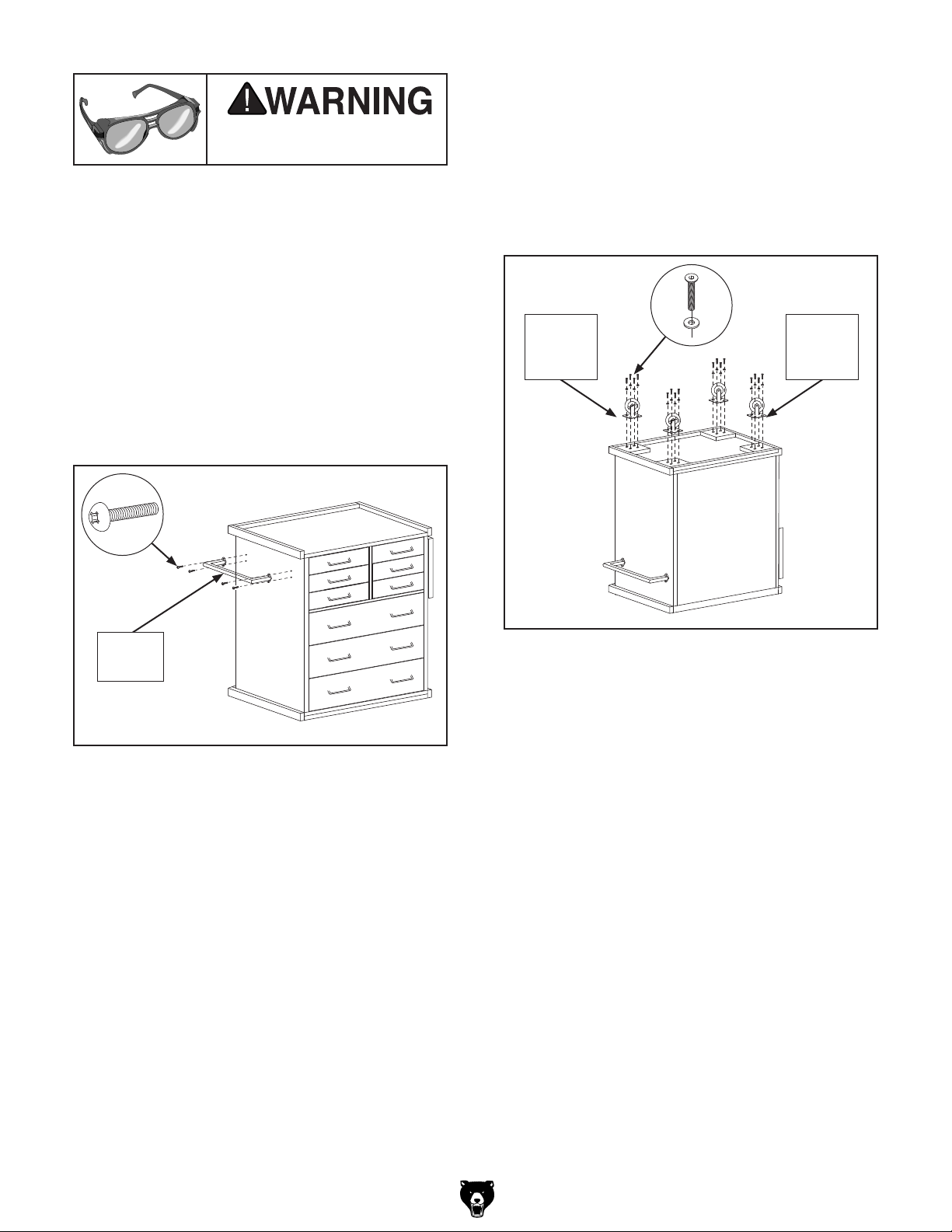
1. Align push handle with pre-drilled holes in cabi-
............................................................ 1
............................ 1
.............................................. 1
1
net and secure with (4) 10-24 x
⁄2" Phillips head
screws (see Figure 3).
3.
Attach (2) fixed casters and (2) locking swivel
casters to cabinet base with (16) 1⁄4"-20 x 3⁄4"
1
flat head cap screws and
⁄4" flat washers
(see Figure 4).
IMPORTANT: Swivel caster wheels must be
installed on same end of cabinet as push
handle to ensure good steering control.
x16
Locking
Caster
(1 of 2)
Fixed
Caster
(1 of 2)
x 4
Push
Handle
Figure 3. Attaching push handle.
With aid of assistant, carefully turn cabinet
2.
upside down.
Note: To avoid damaging wood finish, place
cabinet on a piece of cardboard or other nonscratching surface.
Figure 4. Caster wheels attached.
4. With help of assistant, return cabinet to
upright position and lock caster wheels.
Using Lock Bar
The lock bar can be used to secure the drawers
in the closed position, support the folding table, or
stored out of the way until needed.
Securing Drawers
Ensure drawers are fully closed.
1.
2. Insert key into lock, and rotate key full left so
tab is concealed in tip of lock bar.
-2-
Model T33975 (Mfd. 01/24)
Page 3

3.
Insert wood tongue at bottom of lock bar into
groove in base trim at front of cabinet.
Press lock bar against face of cabinet so it is
4.
flush with table top, then rotate key full right
to lock in position (see Figure 5).
Lock
Lock Bar
Base Trim
Figure 5. Lock bar positioned to secure
drawers.
Storing
1.
Insert key into lock, and rotate key full left so
tab is concealed.
Insert wood tongue at bottom of lock bar into
2.
groove in base trim on left-hand side of cabinet (see Figure 7).
Press lock bar against face of cabinet so it is
3.
flush with table top, then rotate key full right
to lock in position (see Figure 7).
Lock
Lock Bar
Base Trim
Supporting Folding Table
1.
Insert key into lock, and rotate key full right.
Tab will extend from tip of lock bar.
Raise folding table (see Figure 6).
2.
Insert wood tongue at bottom of lock bar into
3.
groove in base trim on right-hand side of
cabinet (see Figure 6).
Align tab at top of lock bar with groove in
4.
underside of table, and lower table onto tab
(see Figure 6).
Folding Table
Lock Bar
Figure 7. Lock bar secured in storage position.
Base Trim
Figure 6. Lock bar positioned to support table.
Model T33975 (Mfd. 01/24)
-3-
Page 4

-4-
Model T33975 (Mfd. 01/24)
 Loading...