

Page 1

MODEL T33955/T33956
ELECTRIC GUITAR KIT
OWNER'S MANUAL
(For models manufactured since 09/23)
COPYRIGHT © DECEMBER, 2023 BY GRIZZLY INDUSTRIAL, INC.
WARNING: NO PORTION OF THIS MANUAL MAY BE REPRODUCED IN ANY SHAPE
OR FORM WITHOUT THE WRITTEN APPROVAL OF GRIZZLY INDUSTRIAL, INC.
#JM22924 PRINTED IN CHINA
***Keep for Future Reference***
V1.12. 2 3
Page 2

Some dust created by power sanding, sawing, grinding, drilling, and
other construction activities contains chemicals known to the State
of California to cause cancer, birth defects or other reproductive
harm. Some examples of these chemicals are:
• Lead from lead-based paints.
• Crystalline silica from bricks, cement and other masonry products.
• Arsenic and chromium from chemically-treated lumber.
Your risk from these exposures varies, depending on how often you
do this type of work. To reduce your exposure to these chemicals:
Work in a well ventilated area, and work with approved safety equipment, such as those dust masks that are specially designed to filter
out microscopic particles.
Page 3

Table of Contents
INTRODUCTION ............................................................................................................................... 2
Contact Info
Description
Manual Accuracy
Identification
.................................................................................................................................2
..................................................................................................................................2
.........................................................................................................................2
................................................................................................................................3
SECTION 1: SAFETY
SECTION 2: SETUP
Unpacking
Planning & Preparation
Needed for Setup
Inventory
SECTION 3: SANDING
Body
Neck
Preparing to Finish
Painting/Finishing
SECTION 4: ASSEMBLY
Routing Wires
Installing Neck
Installing Tremolo Bridge
Installing Output Jack
Installing Strap Buttons
Installing Back Plate
Installing Tuning Machines
Installing Nut
Installing Strings
Installing Pick Guard
Installing String Retainers
...................................................................................................................................5
......................................................................................................................................6
............................................................................................................................................7
............................................................................................................................................7
....................................................................................................................... 4
......................................................................................................................... 5
........................................................................................................................5
.................................................................................................................... 7
......................................................................................................................7
........................................................................................................................8
..............................................................................................................................9
...........................................................................................................................10
.............................................................................................................................15
........................................................................................................................16
...............................................................................................................5
.................................................................................................................. 9
...........................................................................................................11
................................................................................................................12
.............................................................................................................13
..................................................................................................................13
........................................................................................................14
.................................................................................................................17
.........................................................................................................17
SECTION 5: FINAL ADJUSTMENTS
General
Adjusting Neck
Adjusting String Height
Adjusting Pickup Height
Tuning........................................................................................................................................20
Changing Intonation
Adjusting Tremolo Springs
SECTION 6: ACCESSORIES
SECTION 7: WIRING
Wiring Safety Instructions
Wiring Diagram
Electrical Components
SECTION 8: PARTS
Main
WARRANTY & RETURNS
......................................................................................................................................18
..........................................................................................................................18
..............................................................................................................19
............................................................................................................20
..................................................................................................................21
........................................................................................................21
......................................................................................................... 22
...................................................................................................................... 23
.........................................................................................................23
.........................................................................................................................24
..............................................................................................................25
....................................................................................................................... 26
...........................................................................................................................................26
.............................................................................................................. 29
............................................................................................. 18
Page 4

INTRODUCTION
Contact Info
We stand behind our instruments! If you have
questions or need help, contact us using the information below. Before contacting, make sure you
gather all the information regarding your instrument. This will aid us in helping you faster.
Grizzly Technical Support
1815 W. Battleeld
Springeld, MO 65807
Phone: (570) 546-9663
Email: techsupport@grizzly.com
We want your feedback on this manual. What did
you like about it? Where could it be improved?
Please take a few minutes to give us feedback.
Address your concerns or recommendations to:
Grizzly Documentation Manager
P.O. Box 2069
Bellingham, WA 98227-2069
Email: manuals@grizzly.com
Manual Accuracy
We are proud to provide a high-quality owner's
manual with your new instrument!
We make every effort to be exact with the instructions, specifications, drawings, and photographs
in this manual. Sometime we make mistakes, and
our policy of continuous improvement also means
that sometimes the instrument you receive is
slightly different than shown in the manual.
If you find this to be the case, and the difference
between the manual and instrument leaves you
in doubt, check our website (grizzly.com) for an
updated version. We post current manuals and
manual updates for free on our website.
Alternatively, you can call our Technical Support
for help. Before calling, gather all material and
instructions that came with your instrument for
easy reference. This will make providing you
proper technical support much easier. It also will
help us determine if updated documentation is
available for your instrument.
Description
The Grizzly electric guitar kits are made of solid
mahogany and are available with two veneer
options:
—T33955 Quilted Maple
—T33956 Fiddleback Maple
T33955
T33956
-2-
NOTICE
WE STRONGLY RECOMMEND that you read
books, review industry trade magazines, or
get formal training before beginning any
projects. Regardless of the contents in
this Manual, Grizzly Industrial will not be
held liable for accidents caused by lack
of training.
Model T33955 T33956 (Mfd. Since 09/23)
Page 5

Identification
Become familiar with the names and locations of the features shown below to better understand the
instructions in this manual.
Pickups
Dual
Humbucker-
Style
Pickups
Tremolo
Bridge
Tuning Machine
Nut
Fret
Strings
Headstock
String Guides
Fretboard
Fret Inlay/Markers
Neck
Pickup Switch
Volume
Knob
Body
Tremolo
Bar
Strap Pin
There is potential danger when operating
woodworking machinery. Accidents are frequently caused by lack of familiarity or failure to pay attention. Use any machines with
respect and caution to decrease the risk of
operator injury. If normal safety precautions
are overlooked or ignored, serious personal
injury may occur.
Model T33955 T33956 (Mfd. Since 09/23)
Tone
Knobs
1
⁄4" Output
Jack
No list of safety guidelines can be complete. Every shop environment is different.
Always consider safety first, as it applies
to your individual working conditions. Use
tools and any machinery with caution and
respect. Failure to do so could result in serious personal injury, damage to equipment,
or poor work results.
-3-
Page 6

SECTION 1: SAFETY
Always wear safety glasses or goggles when operating equipment. Everyday glasses or reading glasses are not safety glasses. Be certain the safety glasses you wear meet the appropriate standards of
the American National Standards Institute (ANSI).
Because there are various ways to cut and join wood, you can make substitutions for the methods
stated in this plan. We try to suggest the easiest methods possible. However, only you know your skills
with each piece of machinery. Never compromise your safety by using a cutting method with which you
are not comfortable. Instead, find an alternative approach that will yield the same result.
These instructions assume that you are intimately familiar with the safe operation and use of woodworking machinery and woodworking tools, and understand the techniques used to reproduce this project.
If you do not qualify for both of these criteria, STOP building this project for your own safety. Read and
understand the owner’s manual for the machinery you intend to use, take a woodworking class or visit
your local library for more information. Woodworking machinery and tools are inherently dangerous,
because they use sharp edges that can and will cause serious personal injury including amputation
and death. Do not underestimate the ability of these tools and machinery to cause injury. Never operate any tool without all guards in place and always wear approved safety glasses. For your own safety,
please heed this warning.
-4-
Model T33955 T33956 (Mfd. Since 09/23)
Page 7

SECTION 2: SETUP
Needed for SetupUnpacking
This instrument was carefully packaged for safe
transport. When unpacking, separate all enclosed
items from packaging materials and inspect them
for shipping damage. If items are damaged,
please call us immediately at (570) 546-9663.
IMPORTANT: Save all packaging materials until
your are completely satisfied with the instrument
and have resolved any issues between Grizzly or
the shipping agent. You must have the original
packaging to file a freight claim. It is also extremely helpful if you need to return your instrument.
Wear safety glasses during
the entire setup process!
Planning &
Preparation
Total time building this instrument will vary on
many factors. Variables such as glue manufacturer's instructions and curing time, temperature and
humidity at the time of building, and your schedule
are just a few of the factors that can affect the
length of time spent on this project.
Perhaps the biggest determinant of time spent
completing this instrument will be the type of finish and the finishing process used. Finishing this
instrument can be as simple as applying a single
coat of stain or lacquer that can be done relatively quickly, up to a multi-coated finish that takes
weeks to harden.
The following items are needed, but not included,
for the setup/assembly of this instrument.
Description Qty
• Safety Glasses ........................................... 1
• NIOSH-Approved Respirator ...................... 1
• Sanding Block ............................................ 1
• Drill Press or Cordless Drill w/Depth Stop ... 1
• Drill Bit Set.................................................. 1
•
Phillips Screwdriver Set
• Pencil .......................................................... 1
• Sanding Block ............................................ 1
• Hobby Knife or Razor Blade ...................... 1
• Wood File Set ............................................. 1
•
Soldering Iron and Solder
• T-Handle Reamer (1⁄8" to 5⁄8") ..................... 1
• Non-Marring Mallet ..................................... 1
• Wire Cutters ............................................... 1
• Needle Nose Pliers .................................... 1
• Feeler Gauge Set ....................................... 1
•
18" Metal Straightedge (1⁄32" Resolution)
• Wood Glue ................................. As Needed
• Super Glue ................................. As Needed
• C-Clamps ................................... As Needed
• Disposable Gloves ..................... As Needed
• Sandpaper #180, #240, #320,
• #800, #1000 ............................... As Needed
•
Tack Cloth or Soft Cloth
• Masking Tape or Painter's Tape . As Needed
• Finishing Supplies ...................... As Needed
• Tack Cloth................................... As Needed
• Lint-Free Rags ............................ As Needed
• Wooden Blocks .......................... As Needed
• Wooden Shims ........................... As Needed
• Wood File Set (Optional) ............................ 1
............................... 1
............................ 1
...... 1
............... As Needed
Careful planning and budgeting ample time will
make this project easier and ensure you end up
pleased with your results. Good luck building your
instrument, and Grizzly hopes it turns out looking,
and sounding great.
Model T33955 T33956 (Mfd. Since 09/23)
-5-
Page 8

Inventory
The following is a list of items shipped with your
instrument. Before beginning assembly, lay these
items out and inventory them.
If any non-proprietary parts are missing (e.g.
strings, or tuning machine screws), we will gladly
replace them; or for the sake of expediency,
replacements can be obtained at your local music
shop.
NOTICE
If you cannot find an item on this list, carefully check around/inside the machine and
packaging materials. Often, these items get
lost in packaging materials while unpacking or they are pre-installed at the factory.
Body and Neck (Figure 1
A. Body ........................................................... 1
B. Neck ........................................................... 1
) Qty
D
C
F
Figure 2. Electrical components.
Guitar Components (Figure 3) Qty
I. Neck Plate .................................................. 1
J. Neck Plate Gasket ...................................... 1
K. Hex Wrenches 1.5, 4mm ......................1 Ea.
L. Back Plate .................................................. 1
M. Tremolo Bar ................................................ 1
N. Tuning Machines ........................................ 6
O. Strap Buttons.............................................. 2
P. String Set .................................................... 1
Q. String Retainers .......................................... 2
R. Bushings 4 x 5 x 3mm ................................ 2
S. Tuning Machine Seats ................................ 6
T. Tuning Machine Washers ........................... 6
G
H
E
A
Figure 1. Body and neck.
Electrical Components (Figure 2)
C. Pick Guard .................................................. 1
D. Output Jack ................................................ 1
E. Guitar Cable ............................................... 1
F. Tremolo Springs ......................................... 3
G. Spring Hanger ............................................ 1
H. Tremolo Bridge ........................................... 1
B
Qty
I J K L
M
Q
Figure 3. Guitar components.
Hardware (Not Shown):
U. Phillips Head Screws M2 x 14 .................... 6
V. Phillips Head Screws M2.5 x 14 ................. 2
W. Phillips Head Screws M3 x 12 .................. 27
X. Phillips Head Screws M3.5 x 25................. 2
Y. Phillips Head Screws M3.5 x 30 ................ 6
Z. Phillips Head Screws M4 x 50.................... 2
AA. Phillips Head Screws M5 x 45 ................... 4
N
R
O
S
P
T
-6-
Model T33955 T33956 (Mfd. Since 09/23)
Page 9

SECTION 3: SANDING
Body
The guitar body was assembled and rough sanded at the factory; however, no finish has been
applied. The joint cavity where the neck meets the
body and the electronic component holes should
NOT be sanded.
To sand body:
1. Sand body with #180-grit aluminum-oxide
sandpaper until there is a consistent scratch
pattern on entire surface.
Note: When hand sanding, always sand in
same direction as wood grain.
Repeat Step 1 with #240-grit sandpaper.
2.
3. Repeat Step 1 with #320-grit sandpaper.
Wipe body with a damp, lint-free cloth. Wiping
4.
workpiece with a damp cloth before final
sanding helps "raise" wood grain; thus allowing "raised" grain to be sanded smooth.
Neck
Like the guitar body, most of the guitar neck has
been machined and rough sanded at the factory;
however, the neck headstock can be customized
to reflect personal taste. Additional cutting, inlay,
or design work can give a guitar that personalized,
custom look that makes it unique.
Note: If you do choose to customize the neck area
take your time with this sub-section and consider
testing ideas on scrap wood before performing the
work on the actual headstock.
To sand neck:
1. Perform any custom cutting, inlay, or design
work to headstock.
2. Using sanding technique described in previ-
ous sub-section, sand entire guitar neck.
Note: DO NOT sand fretboard. Sanding
fretboard will affect playability of guitar and
could lead to irreparable damage.
Resand entire body with #320 sandpaper to
5.
sand to "raised" grain smooth.
Wipe body with a tack cloth to remove all
6.
remaining sanding dust.
Damage to your eyes and lungs could result
from dust created by sanding without proper
protective gear. Always wear safety glasses and a NIOSH-approved respirator when
sanding.
Model T33955 T33956 (Mfd. Since 09/23)
Preparing to Finish
In preparation for applying the finish, cover the
fretboard, neck pocket, and guitar body cavities
with masking tape or painter's tape.
Carefully press all masking tape edges securely
to the guitar pieces. Finish can seep under
these edges, especially near corners and uneven
edges, and where frets meet the fretboard.
Note: Failure to properly mask these areas can
result in irreparable damage to the guitar.
-7-
Page 10

Painting/Finishing
Note: Always follow finish manufacturer’s
instructions.
Finishing supplies are not supplied with the guitar
kit.
There are many resources (books, videos, websites) that discuss guitar finishing. Grizzly recommends consulting these sources before finishing
your instrument.
Listed below are a few general tips that can be
helpful in finishing your instrument.
Painting/Finishing Tips:
• Always work in a well ventilated area when
using finishing materials.
• Wear an ANSI-approved respirator mask and
safety glasses when using finishing materials!
• Fabricate hooks from metal hangers to suspend guitar components during finishing
process.
• Dust particles suspended in air will settle on
wet finishes, resulting in less than satisfactory results. To avoid this problem:
1. Have guitar components positioned for fin-
ish application upon entering room.
Leave room where finishing will take place
2.
completely undisturbed for 24 hours prior
to applying finish.
Avoid making unnecessary movements
3.
upon entering finish room.
Apply finish to desired guitar parts and
4.
immediately leave finish room.
DO NOT return to room until specified dry-
5.
ing time has elapsed.
• Several thinner coats usually produce a nicer
finish than one heavy coat.
-8-
Model T33955 T33956 (Mfd. Since 09/23)
Page 11

SECTION 4: ASSEMBLY
Routing Wires
Before proceeding with the assembly, three wires
must be routed from the volume control potentiometer on the back of the pick guard to their
proper places on the guitar body.
To route wires:
1. Lay pick guard face down on guitar body.
2. Push (1) black ground wire through hole
that leads to rear cavity in back of guitar, as
shown in Figure 4. This wire will be soldered
to spring hanger in later step.
Push (1) black wire and (1) yellow wire
3.
through hole leading to output jack cavity
shown in Figure 4. These will be soldered to
output jack in later step.
4. Place pick guard on guitar body as shown in
Figure 5, and temporarily secure with mask-
ing tape. Attached pickups should fit into
routed channels.
Apply Masking Tape
to These Areas
Figure 5. Pick guard placed on body.
DO NOT install screws at this time! Final
5.
adjustments will be made after installing
strings.
To Rear
Cavity
Output Jack
Cavity
Figure 4. Wires correctly routed.
Model T33955 T33956 (Mfd. Since 09/23)
-9-
Page 12

Installing Neck
Unless otherwise indicated, we strongly recommend using a drill press for the majority of drilling
to obtain the most precise results. However, an
electric/cordless drill fitted with a depth stop or a
drill stand can be used if you do not have a drill
press.
We recommend using a hollow punch to carve
out holes in the finish before drilling. Also, a router
pad placed under the guitar can help reduce
scratches on the finish.
To mount neck:
Insert neck into neck pocket (see Figure 6),
1.
and check to make sure neck and body are
flush.
— If there is a gap between neck and body,
lightly sand high points on neck until it fits
in pocket.
4.
Insert a 5⁄32" drill bit by hand into each pre-
drilled neck hole (see Figure 7). While pressing down slightly, twist drill bit to make pilot
holes in neck.
Neck Mounting
Hole (1 of 4)
Figure 7. Making a pilot hole in neck.
5. Place neck plate and neck plate gasket on
top of body so a mounting hole extends
beyond body and neck (see Figure 8).
Insert (1) M5 x 45 Phillips head screw through
6.
plate and gasket (see Figure 8).
Neck
Pocket
Figure 6. Example of mounting neck.
Using a C-clamp, press neck and body
2.
together.
Set guitar facedown on top of several 2x4's
3.
(cut to 6" or 12") for support.
Gently mark screw tip depth on neck with a
7.
pencil (see Figure 8).
Note: You may want to cover screw tip
marking location with masking tape to avoid
scratching finish.
Figure 8. Depth of screw tip marked on neck.
-10-
Model T33955 T33956 (Mfd. Since 09/23)
Page 13

8. Set neck face down on drill press table, lower
bit to touch mark made in Step 4, then adjust
drill press to stop at this mark.
9. Lower 5⁄32" drill bit over center of pilot holes
and drill holes to correct depth.
10. Place neck plate on body.
Installing
Tremolo Bridge
The tremolo bridge is used to change the pitch of
the strings on the guitar.
Note: DO NOT glue neck to body.
Align mounting holes in neck, body, neck plate,
11.
and neck plate gasket.
Secure neck with (4) M5 x 45 Phillips head
12.
screws (see Figure 9).
Note: Shims may need to be placed between
neck and neck pocket to ensure proper
height of fretboard upon installation if neck
and fretboard are not even.
To attach tremolo bridge:
1. Place tremolo bridge in cut-out shown in
Figure 10.
Tremolo
Bridge
Tremolo Arm
Location
Figure 10. Example of tremolo bridge placement.
2. Test fit tremolo bridge and use a pencil to
mark location of mounting holes.
1
Use
3.
⁄16" drill bit to pre-drill marked holes.
Figure 9. Mounting neck to body.
x 4
Secure tremolo bridge to guitar body with (6)
4.
M3.5 x 30 Phillips head screws.
Turn guitar body over and place spring hang-
5.
er in cavity, as shown in Figure 11.
Ground
Wire
Ground Wire
Spring
Hanger
Figure 11. Spring hanger placement.
Solder Point
Model T33955 T33956 (Mfd. Since 09/23)
-11-
Page 14

6. Secure spring hanger to guitar body with (2)
M4 x 50 Phillips head screws, as shown in
Figure 12. Tighten screws until spring hanger
is 1" from wall of cavity.
Clean a spot on top of spring hanger to
7.
remove grease and dirt, then solder black
ground wire from Step 2 on Page 9 to spring
hanger, as shown in Figure 12.
Installing
Output Jack
The output jack transfers the signal from the
guitar to the instrument cable and amplifier to
produce sound.
Stretch three springs from spring hanger to
8.
tremolo bridge, as shown in Figure 12.
1"
x 2
Ground
Wire Solder
Point
Figure 12. Springs and spring hanger installed,
and ground wire soldered to hanger.
— If springs are too loose and will not grasp
spring hanger, tighten screws to move
hanger closer to body.
Turn guitar face up and ensure that tremelo
9.
bridge is sitting flat on face of guitar. Loosen
or tighten screws until tremelo sits perfectly
flat.
Spring
(1 of 3)
To attach output jack:
1. Solder (1) black wire and (1) yellow wire from
Step 3 on Page 9 to tabs on output jack, as
shown in Figure 13.
Solder
Points
Figure 13. Wires soldered to output jack tabs.
2. Insert output jack assembly into cavity on
guitar body and secure with masking tape.
Use a 3⁄32" drill bit to drill two 3⁄8" deep holes
3.
through holes in output jack.
4. Secure output jack to guitar body with (2) M
x 12 Phillips head
screws (see Figure 14).
3
Screw tremolo arm into tremolo arm socket,
10.
as shown in Figure 14.
-12-
Tremolo
Arm
Socket
x 2
Figure 14. Output jack and tremolo arm
Model T33955 T33956 (Mfd. Since 09/23)
Tremolo
Arm
installed.
Page 15

Installing
Strap Buttons
The strap buttons are positioned on the guitar, as
shown in Figure 15.
Installing Back Plate
To simplify installing and removing the strings, the
slots in the back plate must align with the string
holes in the bottom of the tremolo bridge.
To install back plate:
x 2
Figure 15. Strap button placement.
To install strap buttons:
Strap Button
(1 of 2)
1. Turn guitar face down, position back plate
over cavity in back of guitar body, as shown
in Figure 16.
Note: Make sure slots in back plate are cen-
tered over tremolo string holes.
x 6
Figure 16. Correct position of back plate.
1. Use a 3/32" drill bit to drill 1/2" deep holes at
locations shown in Figure 15.
2. Use (2) Phillips head screws provided with
strap buttons to secure each button to guitar
body (see Figure 15).
Model T33955 T33956 (Mfd. Since 09/23)
2. Secure position of back plate to guitar body
with masking tape.
Use a 3⁄32" drill bit to drill 5⁄16" deep holes
3.
straight through six holes in back plate.
Remove protective plastic film from back
4.
plate.
Secure back plate to guitar body with (6) M3
5.
x 12 Phillips head screws, and remove masking tape (see Figure 16).
-13-
Page 16

Installing
Button
Secure tuning machines to headstock with
3.
screws, as shown in Figure 18.
Tuning Machines
The supplied tuning machines are easily installed.
Each tuning machine consists of the parts shown
in Figure 17.
Headstock
Tuning
Machine
Screw
Figure 17. Tuning machine components.
Tuning Machine Seat
Tuning Machine
Washer
Tuning Machine Post
Tuning Machine
Note: Use a straightedge to make sure tun-
ers are aligned. Adjust if necessary.
Ensure
Tuners are
Aligned
x 6
Figure 18. Tuning machines installed and
aligned on headstock.
To install tuning machines:
1. Using a non-marring mallet, tap each of (6)
machine seats and washers into pre-drilled
holes on front of headstock.
2. From back of headstock, slide posts through
headstock and secure in seats (see Figure
17).
Note: Position tuning machine buttons away
from headstock.
-14-
Model T33955 T33956 (Mfd. Since 09/23)
Page 17

Installing Nut
2. Test fit nut in slot, ensuring large grooves
face toward top of neck, as shown in Figure
19.
The nut is located at the top of the fretboard and
holds the strings in place. The nut can be held in
place with string tension, or it can be spot glued
in place for more security.
If you prefer to glue, we recommend using wood
glue so that future adjustments can be made. For
a more permanent bond, super glue can be used,
but future adjustments will be more difficult.
ALWAYS follow the adhesive manufacturer's instructions for your safety and best
results.
To install nut:
Use a hobby knife or razor blade to scrape
1.
any finish out of nut slot (see Figure 19). DO
NOT remove any wood from nut slot.
Note: Curved part of nut should face head-
stock.
— If nut fits snugly in slot, proceed to Step 3.
— If nut does not fit in slot, sand one side on
a piece of sandpaper until it fits snugly in
slot.
Nut
Large
Grooves
Figure 19. Nut installed.
Remove nut, spread a thin layer of glue in
3.
nut slot, and install nut in slot, ensuring it is
centered from side to side.
Clamp nut in place.
4.
5. Wipe away excess glue with a damp cloth,
and allow glue to dry for 24 hours.
Model T33955 T33956 (Mfd. Since 09/23)
-15-
Page 18

Installing Strings
The correct position of the guitar strings is shown
in Figure 20. The thin High "E" string is the "1st"
string, and the thick Low "E" string is the "6th."
6
E
A
5
4
D
D
G
3
B
2
1
E
Figure 20. Correct string locations.
3rd4th5th6th
2nd 1st
Figure 22. String installed in tuning machines.
3.
Allow only enough slack in string for 2–3 rota-
tions around tuning machine post.
Note: If too much slack is allowed, then string
could wind off tuning machine post after
many successive rotations. If not enough
slack is allowed, then string may not hold
winding tension.
To install strings:
Slide 1st string through corresponding hole in
1.
tremolo bridge (see Figure 21).
2. Guide string through tremolo bridge, across
saddle (see Figure 21), over nut, and through
hole in corresponding tuning machine
(see Figure 22).
1st String
Saddle
Figure 21. Example of 1st string installed.
Bend string at a right angle across edge of
4.
tuning machine post.
Rotate tuning machine until string just begins
5.
to hold winding tension (see Figure 23), and
so string is on right side of tuning machine
post.
Note: DO NOT tighten strings beyond initial
tensioning at this time. Final tensioning will
be completed during string tuning process.
Tuning
Machine
Post
To
Neck
-16-
Figure 23. String wrapped around tuning
machine post.
6.
Use wire cutters to cut off excess string.
7. Repeat above process for remaining strings.
Model T33955 T33956 (Mfd. Since 09/23)
Page 19
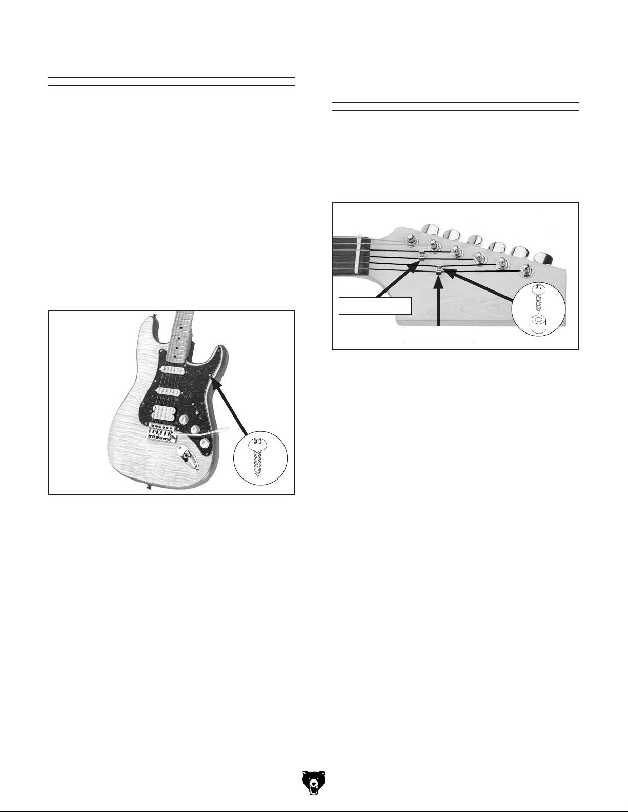
Installing Pick Guard Installing
String Retainers
Now that the electronics components have been
installed, the pick guard can be permanently
installed.
To install pick guard:
1. Use a 3⁄32" drill bit to drill 5⁄16" deep holes
through eleven holes in pick guard (see
Figure 24).
Remove protective plastic film from pick
2.
guard.
Secure pick guard to guitar body with (19) M3
3.
x 12 Phillips head screws (see Figure 24).
The string retainers mount between the 1st and
2nd strings, and between the 3rd and 4th strings
(see Figure 25). String retainers are designed to
hold the strings down against the nut to enable
correct tuning.
2nd Retainer
1st Retainer
Figure 25. String retainer locations.
x 2
Figure 24. Pick guard installed on body.
4.
Remove masking tape.
x 12
To install string retainers:
1. Place 1st string retainer on top of 1st and 2nd
strings near second tuner and loosen strings
several turns.
Using a 1⁄16" drill bit positioned through string
2.
retainer, drill a
Note: Drilling hole deeper than 1⁄2" could
result in drilling through bottom of headstock.
Slide screw provided with retainer through
3.
retainer and bushing, then fasten it to headstock (see Figure 25).
Place 2nd string retainer on top of 3rd
4.
and 4th strings, loosen strings, and repeat
Steps 2–3.
1
⁄4" deep hole into headstock.
Model T33955 T33956 (Mfd. Since 09/23)
-17-
Page 20

SECTION 5: FINAL ADJUSTMENTS
General
Guitar setup is an art that requires skill, patience,
and experience. If you have the patience, you can
acquire the skill and experience. If you don't have
the patience, you may want to have your guitar set
up by a qualified guitar technician.
This section presents an overview of setup practices. We highly recommended that you research
more in-depth methods. Books on setting up
electric guitars can be ordered through Grizzly
Industrial, luthier supply catalogs, or may be available through your local library.
Adjusting Neck
The guitar neck was adjusted perfectly straight
before it was packaged. However, the moisture
content of wood acclimates to the humidity of the
surrounding environment, and this can result in
wood movement that affects alignment. The neck
may require adjustment several times a year,
particularly in regions where the seasonal climate
changes are more drastic.
— If neck is bowed less than 0.012", no
adjustment is necessary. Proceed to
Adjusting String Height on Page 19.
— If neck is bowed more than 0.012", pro-
ceed to Step 4.
Loosen strings so there is no tension on
4.
neck.
Locate truss rod nut at bottom of headstock
5.
(see Figure 26) and turn counterclockwise to
release tension on neck. Now tighten nut until
it just begins to grab.
— To flatten a down bow, turn truss rod nut
1
⁄4 turn clockwise. To correct an up bow,
a
turn nut a
Truss
Rod
Nut
1
⁄4 turn counterclockwise.
Tools Needed
Hex Wrench 4mm .............................................. 1
Straightedge
Feeler Gauge
To adjust neck:
1. DISCONNECT GUITAR FROM AMP!
2. Tighten strings to playing tension.
3. Place a straightedge on fretboard, stretch-
ing from 1st fret to 17th. Measure any gaps
between straightedge and frets with feeler
gauge.
-18-
...................................................... 1
..................................................... 1
Figure 26. Location of truss rod nut.
6.
Tighten strings to playing tension, and check
neck with straightedge.
— If neck is correctly adjusted, go to
Adjusting String Height on Page 19.
— If neck is still out of adjustment, repeat
Steps 4–5.
Model T33955 T33956 (Mfd. Since 09/23)
Page 21

Adjusting
String Height
Correct string height (or action) is crucial for maximizing the playability of your electric guitar. The
string height is the distance between the top face
of the fret and the bottom face of the string (see
Figure 27). The ideal string height typically falls
within a range of 0.060"–0.080" measured at the
12th fret.
String
String Height
Fret
To adjust string height:
1. DISCONNECT GUITAR FROM AMP!
2. Measure height of each string above 12th
fret.
Adjust saddle height (see Figure 28) for each
3.
string until it is 0.060"–0.080" above 12th fret.
Saddle
(1 of 6)
Fretboard
Figure 27. String height measurement.
Tool Needed
Hex Wrench 1.5mm
........................................... 1
Figure 28. Example of adjusting string height.
Tune guitar if necessary.
4.
Model T33955 T33956 (Mfd. Since 09/23)
-19-
Page 22
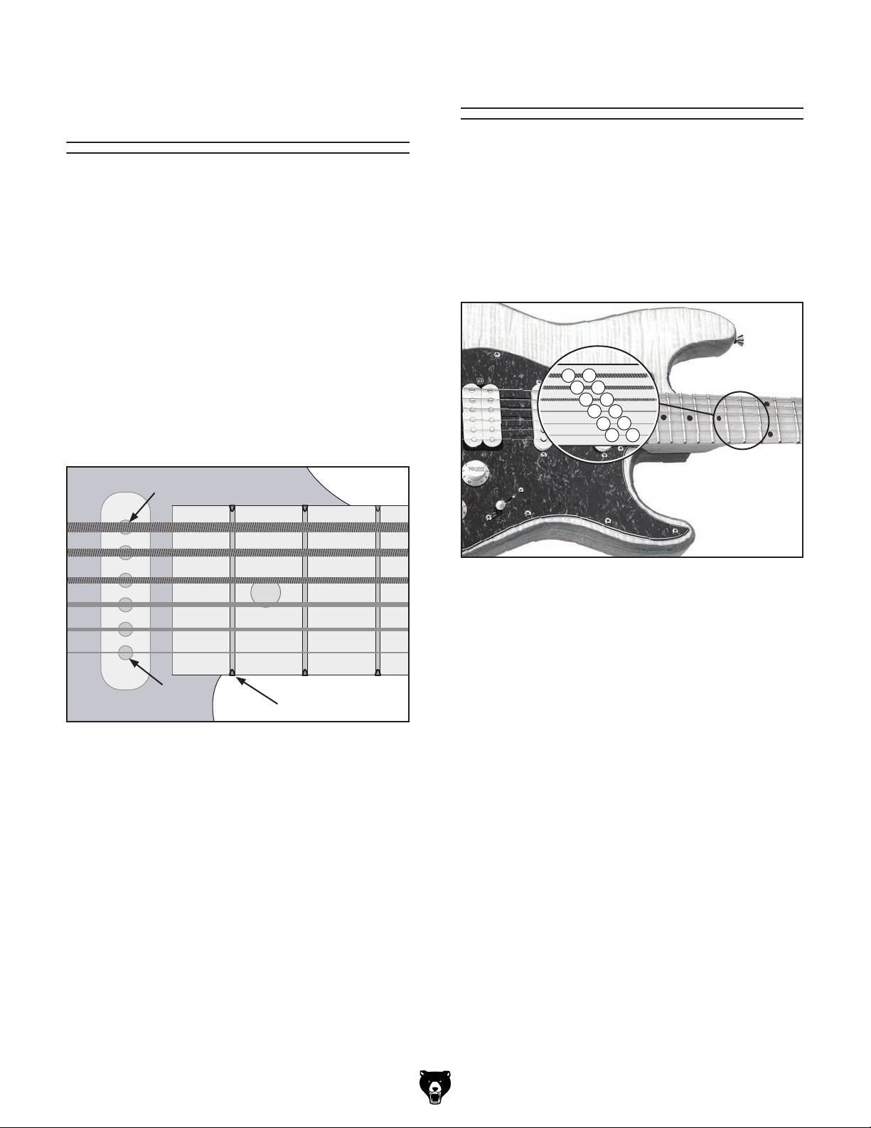
Adjusting
Pickup Height
Pickup height can have a dramatic effect on the
audio output signal. The closer the strings are to
the pickup, the higher the audio output signal will
be. If the strings are too close, distortion is caused
by magnetic interference from the electronic
components.
Tool Needed
Phillips Head Screwdriver #2
............................ 1
Tuning
Tuning is the most important concept of playing a
guitar. If the guitar is not in tune with itself, or the
other instruments in an ensemble, the resulting
music will not sound pleasing to the ear.
The easiest way to tune a guitar is using an electronic tuner. There are a wide variety of these
available in music stores and online.
To adjust pickup height:
1. Measure height of 1st and 6th strings at
pickup while strings are "fretted" at 22nd fret
(see Figure 29).
1
/8"
3
/32"
22nd Fret
Figure 29. String heights over pickup.
Adjust screws on each side of pickup until 1st
2.
string is 3⁄32" above pickup and 6th string is 1⁄8"
above pickup.
— Turn screws clockwise to raise height of
pickup.
— Turn screws counterclockwise to lower
height of pickup.
Repeat Steps 1–2 for other pickups.
3.
6
E
A
5
4
D
D
G
3
B
2
1
E
Figure 30. Example of standard tuning.
To tune guitar:
1. Play a low E Pitch on a piano, a tuning fork,
or an electronic computer file.
Play an open (non-fretted) 6th string and
2.
adjust tuner to match low E.
Note: Always tune up. If string is tuned high,
loosen string to lower pitch, then tune string
up to correct note.
Tune 5th string by playing 6th string while it
3.
is being pressed (fretted) at 5th fret, and then
play open 5th string. Adjust 5th string tuner
until notes match.
Tune 4th string by playing 5th string while it
4.
is being pressed (fretted) at 5th fret, and then
play open 4th string. Adjust 4th string tuner
until notes match.
-20-
Model T33955 T33956 (Mfd. Since 09/23)
Page 23
5. Perform same tuning step on 3rd and 4th
string.
When tuning 2nd string, fret 3rd string at 4th
6.
fret instead of 5th fret.
Tune 1st string in same manner as 6th, 5th,
7.
4th, and 3rd strings.
Changing Intonation
Changing intonation adjusts the length of the
string to correct for flatness/sharpness on each
string. This is a simple process, but it does require
some trial-and-error.
Tool Needed
Phillips Head Screwdriver #2
To change intonation:
1. Lightly touch and then release 1st string
directly above twelfth fret as you pluck string
to play a harmonic note.
Now pluck string while holding it fretted at
2.
twelfth fret. If this note is sharper than note
played in Step 1, move saddle away from
neck by turning saddle adjustment screw
(see Figure 31) clockwise. If this note is flat
in comparison, move saddle toward neck.
............................ 1
Note: This can also be done with an elec-
tronic tuner by tuning harmonic note to be
exactly in tune and then adjusting saddle until
note played in Step 2 is also in tune.
Repeat Steps 1 –2 until string is in tune.
3.
Repeat process for remaining strings.
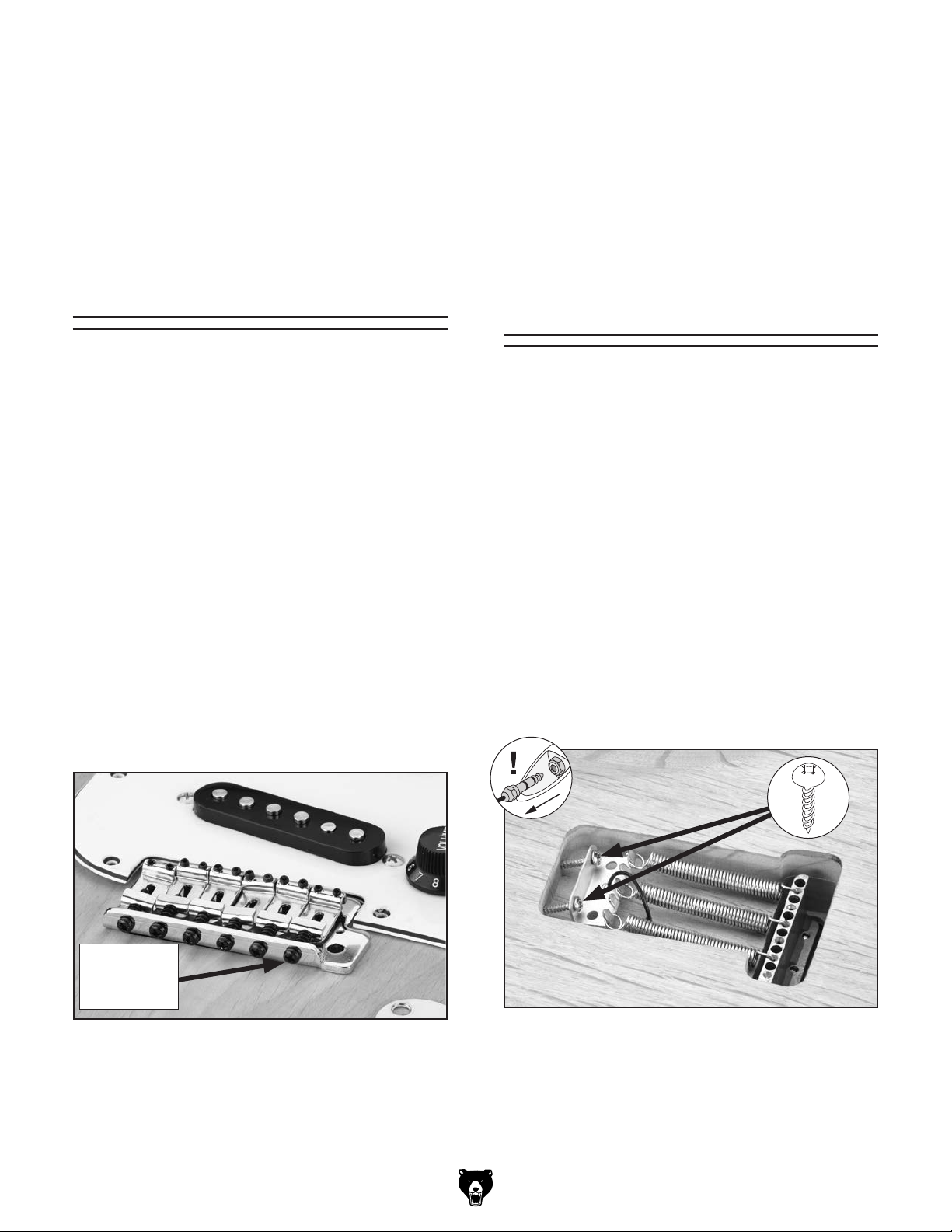
Adjusting
Tremolo Springs
The pitch of the guitar can be changed by adjusting the tension on the tremelo springs.
Tool Needed
Phillips Head Screwdriver #2 ............................ 1
To adjust tremolo springs:
DISCONNECT GUITAR FROM AMP!
1.
2. Remove back plate.
3. Locate (2) Phillips head screws securing
spring hanger (see Figure 32).
— Tighten screws to increase pitch.
— Loosen screws to decrease pitch.
Adjustment
Screw
(1 of 6)
Figure 31. Example of saddle adjustment screw.
Model T33955 T33956 (Mfd. Since 09/23)
x 2
Figure 32. Location of tremelo springs.
Note: Standard position of spring hanger is
approximately
When satisfied with adjustment, replace back
4.
plate, and tune guitar.
5
⁄8" from front edge of cavity.
-21-
Page 24
ACCESSORIES
order online at www.grizzly.com or call 1-800-523-4777
SECTION 6: ACCESSORIES
NOTICE
Refer to our website or latest catalog for
additional recommended accessories.
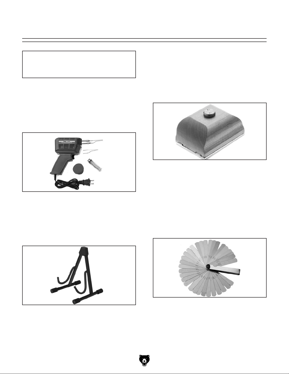
T1233—High Speed Soldering Gun Kit
Designed for professional users, this fast-heating,
pistol grip soldering gun is comfortable and easy
to use. This soldering gun features a comfortable
pistol grip and is designed for quick tip replacement. It also includes a built-in light to better illuminate your workpiece.
D2823—Shop Fox Sanding Block - Small
This beautiful hardwood sanding block features
a felt pad, ergonomically shaped body and convenient sandpaper attachment and removal. Topmounted knurled brass knob mechanism secures
sandpaper so there's no slipping or tearing. Small
block measures 3" x 4" and uses one sixth sanding sheet.
Figure 33. T1233 High Speed Soldering Gun Kit.
H5962—Guitar Stand-Electric/Archtop
A stable guitar stand that keeps electric and
archtop guitars safe yet accessible on stage or
on display. Folds up for easy transporting. Three
adjustable locking positions. Padded protection at
all contact points and non-slip rubber feet.
Figure 35. D2823 Shop Fox Sanding Block -
Small.
G9616—Feeler Gauge Set - 32 Pc.
This 3
and accurate method of determining gap widths.
Includes: .0015", .002", .0025", .003", .004", .005",
.006", .007", .008", .009, .010", .010", .011", .012",
.013", .014", .015", .016 ", .017", .018", .019", .020",
.021", .022", .023", .024", .025", .026", .028",
.030", .032" and .035" blade thickness. Case not
included.
1
⁄2 " long Feeler Gauge Set provides a quick
Figure 36. G9616 Feeler Gauge Set - 32 Pc.
Figure 34. H5962 Guitar Stand-Electric/Archtop.
-22-
Model T33955 T33956 (Mfd. Since 09/23)
Page 25

These pages are current at the time of printing. However, in the spirit of improvement, we may make changes to the electrical systems of future machines. Compare the manufacture date of your machine to the one
stated in this manual, and study this section carefully.
If there are differences between your machine and what is shown in this section, call Technical Support at
(570) 546-9663 for assistance BEFORE making any changes to the wiring on your machine. An updated
wiring diagram may be available.
number and manufacture date of your
machine before calling. This information can be found on the main machine label.
machine
SECTION 7: WIRING
Note: Please gather the serial
Wiring Safety Instructions
SHOCK HAZARD. Working on wiring that is con-
nected to a power source is extremely dangerous.
Touching electrified parts will result in personal
injury including but not limited to severe burns,
electrocution, or death. Disconnect the power
from the machine before servicing electrical components!
MODIFICATIONS. Modifying the wiring beyond
what is shown in the diagram may lead to unpredictable results, including serious injury or fire.
This includes the installation of unapproved aftermarket parts.
WIRE CONNECTIONS. All connections must
be tight to prevent wires from loosening during
machine operation. Double-check all wires disconnected or connected during any wiring task to
ensure tight connections.
CIRCUIT REQUIREMENTS. You MUST follow
the requirements at the beginning of this manual
when connecting your machine to a power source.
WIRE/COMPONENT DAMAGE. Damaged wires
or components increase the risk of serious personal injury, fire, or machine damage. If you notice
that any wires or components are damaged while
performing a wiring task, replace those wires or
components.
MOTOR WIRING. The motor wiring shown in
these diagrams is current at the time of printing
but may not match your machine. If you find this
to be the case, use the wiring diagram inside the
motor junction box.
CAPACITORS/INVERTERS. Some capacitors
and power inverters store an electrical charge for
up to 10 minutes after being disconnected from
the power source. To reduce the risk of being
shocked, wait at least this long before working on
capacitors.
EXPERIENCING DIFFICULTIES. If you are experiencing difficulties understanding the information
included in this section, contact our Technical
Support at (570) 546-9663.
The photos and diagrams
included in this section are
best viewed in color. You
can view these pages in
color at www.grizzly.com.
Model T33955 T33956 (Mfd. Since 09/23)
-23-
Page 26

Wiring Diagram
Pickup
Bk
Pickup
5-Way
Switch
Wt
Tone
Control
Rd
Wt
Tone
Control
Rd
Wt
Bk
Gy
Spring
Hanger
Rd
Bk
Volume
Control
Dual
Humbucker
Wt
Bk
Bk
Pickup
Bk
Output
Jack
-24-
READ ELECTRICAL SAFETY
ON PAGE 23!
Model T33955 T33956 (Mfd. Since 09/23)
Page 27

Electrical Components
Figure 37. Pick guard wiring.
Figure 38. Output jack wiring.
Model T33955 T33956 (Mfd. Since 09/23)
Figure 39. Ground wiring.
READ ELECTRICAL SAFETY
ON PAGE 23!
-25-
Page 28

SECTION 8: PARTS
We do our best to stock replacement parts when possible, but we cannot guarantee that all parts shown
are available for purchase. Call (800) 523-4777 or visit www.grizzly.com/parts to check for availability.
REF P ART # DES CRIPTI ON REF P ART # DES CRIPTI ON
2
24
26
Main
1
5
4
9
10
18
6
11
7
12
20
17
14
15
23
1 PT33955001 BODY QUILTED MAPLE 14 PT33955014 STRING RETAINER
1 PT33956001
2 PT33955002 NECK 16 PT33955016 PHLP HD SCR M2.5 X 14
3 PT33955003 PICK GUARD 17 PT33955017 HEX WRENCH 1.5MM
4 PT33955004 TUNING MACHINE 18 PT33955018 HEX WRENCH 4MM
5 PT33955005 PHLP HD SCR M2 X 14 19 PT33955019 STRING SET
6 PT33955006 OUTPUT JACK 20 PT33955020 TUNING MACHINE SEAT
7 PT33955007 TREMOLO BRIDGE 21 PT33955021 NECK PLATE GASKET
8 PT33955008 SPRING HANGER 22 PT33955022 NECK PLATE
9 PT33955009 TREMOLO ARM 23 PT33955023 PHLP HD SCR M3.5 X 30
10 PT33955010 TREMOLO SPRING 24 PT33955024 PHLP HD SCR M4 X 50
11 PT33955011 STRAP BUTTON 25 PT33955025 PHLP HD SCR M5 X 45
12 PT33955012 BACK PLATE 26 PT33955026 PHLP HD SCR M3 X 12
13 PT33955013 GUITAR CABLE 27 PT33955027 TUNING MACHINE WASHER
BODY FIDDLEBACK MAPLE
16
25
19
15 PT33955015 BUSHING 4 X 5 X 3
3
8
13
21
22
27
-26-
BUY PARTS ONLI NE AT GRIZZLY.COM!
Scan QR code to visit our Parts Store.
Model T33955 T33956 (Mfd. Since 09/23)
Page 29

Page 30

Page 31

WARRANTY & RETURNS
Grizzly Industrial, Inc. warrants every product it sells for a period of 1 year to the original purchaser from
the date of purchase. This warranty does not apply to defects due directly or indirectly to misuse, abuse,
negligence, accidents, repairs or alterations or lack of maintenance. This is Grizzly’s sole written warranty
and any and all warranties that may be implied by law, including any merchantability or fitness, for any particular purpose, are hereby limited to the duration of this written warranty. We do not warrant or represent
that the merchandise complies with the provisions of any law or acts unless the manufacturer so warrants.
In no event shall Grizzly’s liability under this warranty exceed the purchase price paid for the product and
any legal actions brought against Grizzly shall be tried in the State of Washington, County of Whatcom.
We shall in no event be liable for death, injuries to persons or property or for incidental, contingent, special,
or consequential damages arising from the use of our products.
The manufacturers reserve the right to change specifications at any time because they constantly strive to
achieve better quality equipment. We make every effort to ensure that our products meet high quality and
durability standards and we hope you never need to use this warranty.
In the event you need to use this warranty, contact us by mail or phone and give us all the details. We will
then issue you a “Return Number,’’ which must be clearly posted on the outside as well as the inside of
the carton. We will not accept any item back without this number. Proof of purchase must accompany the
merchandise.
Please feel free to write or call us if you have any questions about the machine or the manual.
Thank you again for your business and continued support. We hope to serve you again soon.
For further information about the
scan the QR
code below
to be automatically directed to our warranty page.
warranty, visit https://www.grizzly.com/forms/warranty or
WARRANTY
Page 32

 Loading...