

Page 1

MODEL T33952/T33953/T33954
ACOUSTIC GUITAR KIT
OWNER'S MANUAL
(For models manufactured since 09/23)
COPYRIGHT © NOVEMBER, 2023 BY GRIZZLY INDUSTRIAL, INC., REVISED AUGUST, 2024 (MN)
WARNING: NO PORTION OF THIS MANUAL MAY BE REPRODUCED IN ANY SHAPE
OR FORM WITHOUT THE WRITTEN APPROVAL OF GRIZZLY INDUSTRIAL, INC.
#JM22871 PRINTED IN CHINA
***Keep for Future Reference***
V1.08.24
Page 2

Some dust created by power sanding, sawing, grinding, drilling, and
other construction activities contains chemicals known to the State
of California to cause cancer, birth defects or other reproductive
harm. Some examples of these chemicals are:
• Lead from lead-based paints.
• Crystalline silica from bricks, cement and other masonry products.
• Arsenic and chromium from chemically-treated lumber.
Your risk from these exposures varies, depending on how often you
do this type of work. To reduce your exposure to these chemicals:
Work in a well ventilated area, and work with approved safety equipment, such as those dust masks that are specially designed to filter
out microscopic particles.
Page 3

Table of Contents
INTRODUCTION ............................................................................................................................... 2
Contact Info
Description
Manual Accuracy
Identification
Glossary Of Terms
.................................................................................................................................2
..................................................................................................................................2
.........................................................................................................................2
................................................................................................................................3
......................................................................................................................4
SECTION 1: SAFETY
SECTION 2: SETUP
Unpacking
Planning & Preparation
Needed for Setup
Inventory
SECTION 3: SANDING
Body
Neck
Bridge
Fitting Neck to Body
SECTION 4: ASSEMBLY
Attaching
Neck to Body
Installing Truss Rod
Attaching Fretboard
Determining Bridge Location
Attaching Nut
Preparing to Finish
Painting/Finishing
Attaching Bridge
Fitting Bridge Pins
Attaching Sound Hole Decal
Installing Strap Button
Installing Tuning Machines
Installing Strings
Setting String Height
Guitar Setup
...................................................................................................................................6
......................................................................................................................................7
............................................................................................................................................8
............................................................................................................................................8
..........................................................................................................................................8
..................................................................................................................................10
....................................................................................................................... 5
......................................................................................................................... 6
........................................................................................................................6
.................................................................................................................... 8
.............................................................................................................................10
.............................................................................................................................15
....................................................................................................................15
......................................................................................................................16
........................................................................................................................16
.....................................................................................................................17
........................................................................................................................20
..............................................................................................................................22
...............................................................................................................6
....................................................................................................................9
................................................................................................................ 10
...................................................................................................................11
...................................................................................................................12
.....................................................................................................13
.....................................................................................................18
...............................................................................................................18
........................................................................................................19
.................................................................................................................20
SECTION 5: ACCESSORIES
SECTION 6: PARTS
...........................................................................................................................................24
Main
WARRANTY & RETURNS
....................................................................................................................... 24
.............................................................................................................. 25
......................................................................................................... 23
Page 4

INTRODUCTION
Contact Info
We stand behind our instruments! If you have
questions or need help, contact us using the information below. Before contacting, make sure you
gather all the information regarding your instrument. This will aid us in helping you faster.
Grizzly Technical Support
1815 W. Battleeld
Springeld, MO 65807
Phone: (570) 546-9663
Email: techsupport@grizzly.com
We want your feedback on this manual. What did
you like about it? Where could it be improved?
Please take a few minutes to give us feedback.
Grizzly Documentation Manager
P.O. Box 2069
Bellingham, WA 98227-2069
Email: manuals@grizzly.com
Description
Manual Accuracy
We are proud to provide a high-quality owner's
manual with your new instrument!
We make every effort to be exact with the instructions, specifications, drawings, and photographs
in this manual. Sometime we make mistakes, and
our policy of continuous improvement also means
that sometimes the instrument you receive is
slightly different than shown in the manual.
If you find this to be the case, and the difference
between the manual and instrument leaves you
in doubt, check our website (grizzly.com) for an
updated version. We post current manuals and
manual updates for free on our website.
Alternatively, you can call our Technical Support
for help. Before calling, gather all material and
instructions that came with your instrument for
easy reference. This will make providing you
proper technical support much easier. It also will
help us determine if updated documentation is
available for your instrument.
The Grizzly acoustic guitar kits are available in
three veneer options:
—T33952 Quilted Maple Veneer
—T33953 Fiddleback Maple Veneer
—T33954 Koa Variant
T33953
T33952
T33954
-2-
NOTICE
WE STRONGLY RECOMMEND that you read
books, review industry trade magazines, or
get formal training before beginning any
projects. Regardless of the contents in
this Manual, Grizzly Industrial will not be
held liable for accidents caused by lack
of training.
Model T33952/53/54 (Mfd. Since 09/23)
Page 5

Identification
Become familiar with the names and locations of the features shown below to better understand the
instructions in this manual.
Bridge
Sound
Board
Sound
Hole
Fret Inlay/
Markers
Frets
12th Fret
Nut
Headstock
Saddle Body
There is potential danger when operating
woodworking machinery. Accidents are frequently caused by lack of familiarity or failure to pay attention. Use any machines with
respect and caution to decrease the risk of
operator injury. If normal safety precautions
are overlooked or ignored, serious personal
injury may occur.
Strings
Fret
Board
No list of safety guidelines can be complete. Every shop environment is different.
Always consider safety first, as it applies
to your individual working conditions. Use
tools and any machinery with caution and
respect. Failure to do so could result in serious personal injury, damage to equipment,
or poor work results.
Neck
Tuning
Machines
Model T33952/53/54 (Mfd. Since 09/23)
-3-
Page 6

Glossary Of Terms
The following is a list of common definitions, terms and phrases used throughout this manual as they relate
to this guitar and music in general. Become familiar with these terms for assembling, adjusting, or operating
this instrument.
Acoustic: An instrument that makes sound with
no amplification, utilizing its own construction
and soundhole to project tone and volume.
Action: Setup of strings in relation to instrument
body and neck. Most commonly this relates to
height of strings above fretboard.
Back: Rear face of instrument.
Body: Instrument housing composed of three
main parts—top, sides and back—and holds
bridge on top, connecting to neck of instrument.
Bridge: Wooden piece glued on top of instrument
body and holds saddle. There are four main
types of bridges: slotted, tie bar, through body,
and pin.
Fretboard: Area of neck over which strings run
and into which frets are mounted. Fretboard is
where your fretting hand holds notes by pressing down on strings between frets.
Finish: The manufacture or decoration of an
instrument by giving it an attractive surface
appearance.
Fret: Thin strips of metal set into neck of an instru-
ment to allow changing notes.
Fret Markers: Dots inlaid in fretboard of instru-
ment to help finger placement and locating
notes.
Intonation: Ability of an instrument to play and
hold correct note at any point on neck. This usually refers to quality of an instrument’s construction, and ability for each fret, when depressed,
to sound correct note for its position.
Joint: Where neck meets body of instrument.
Neck: Wood that holds fretboard, and runs
between body of instrument and headstock.
Nut: A strip of material located at top end of
fretboard over which strings are held in slots
prior to tuning pegs.
Tuning Machine: Tuning pegs that work using
a gearing system to turn string post altering
instrument tone.
Tuning Peg: Tuning device that is turned to
tighten or loosen string.
Saddle: Section of instrument over which strings
are secured.
Scale Length: Dimension of string length mea-
sured between nut and saddle. Length needs
to be accurate in relation to placement of frets
to ensure accuracy in notes being played. Top
of 12th fret always denotes exact halfway point
of string.
Sound Board: Flat piece of wood that holds
bridge and sound hole.
Headstock: Flat piece of wood at top of neck that
holds tuning pegs and usually displays instrument brand logo.
Inlay: Material inlaid into surface parts of
instrument.
-4-
Sound Hole: Hole in sound board of instrument
that projects sound.
Model T33952/53/54 (Mfd. Since 09/23)
Page 7

SECTION 1: SAFETY
Always wear safety glasses or goggles when operating equipment. Everyday glasses or reading glasses are not safety glasses. Be certain the safety glasses you wear meet the appropriate standards of
the American National Standards Institute (ANSI).
Because there are various ways to cut and join wood, you can make substitutions for the methods
stated in this plan. We try to suggest the easiest methods possible. However, only you know your skills
with each piece of machinery. Never compromise your safety by using a cutting method with which you
are not comfortable. Instead, find an alternative approach that will yield the same result.
These instructions assume that you are intimately familiar with the safe operation and use of woodworking machinery and woodworking tools, and understand the techniques used to reproduce this project.
If you do not qualify for both of these criteria, STOP building this project for your own safety. Read and
understand the owner’s manual for the machinery you intend to use, take a woodworking class or visit
your local library for more information. Woodworking machinery and tools are inherently dangerous,
because they use sharp edges that can and will cause serious personal injury including amputation
and death. Do not underestimate the ability of these tools and machinery to cause injury. Never operate any tool without all guards in place and always wear approved safety glasses. For your own safety,
please heed this warning.
Model T33952/53/54 (Mfd. Since 09/23)
-5-
Page 8

SECTION 2: SETUP
Needed for SetupUnpacking
This instrument was carefully packaged for safe
transport. When unpacking, separate all enclosed
items from packaging materials and inspect them
for shipping damage. If items are damaged,
please call us immediately at (570) 546-9663.
IMPORTANT: Save all packaging materials until
your are completely satisfied with the instrument
and have resolved any issues between Grizzly or
the shipping agent. You must have the original
packaging to file a freight claim. It is also extremely helpful if you need to return your instrument.
Wear safety glasses during
the entire setup process!
Planning &
Preparation
Total time building this instrument will vary on
many factors. Variables such as glue manufacturers instructions and curing time, temperature and
humidity at the time of building, and your schedule
are just a few of the factors that can affect the
length of time spent on this project.
Perhaps the biggest determinant of time spent
completing this instrument is the type of finish
and the finishing process used. Finishing this
instrument can be as simple as applying a single
coat of stain or lacquer that can be done relatively quickly, up to a multi-coated finish that takes
weeks to harden.
Careful planning and budgeting ample time will
make this project easier and ensure you end up
pleased with your results. Good luck building your
instrument, and Grizzly hopes it turns out looking,
and sounding great.
The majority of the wooden components in this kit
are fully machined from the factory and are ready
for assembly. A small amount of sanding and finishing is required to complete your guitar.
Description Qty
• Safety Glasses (Per Person) ...................... 1
• NIOSH-Approved Respirator (Per Person) .. 1
• Ratchet or Frame Clamp ............................ 1
• Hobby Knife or Chisel ................................ 1
• T-Handle Reamer (1⁄8" to 5⁄8") ..................... 1
• Drill Press or Cordless Drill w/Depth Stop ... 1
• Forstner Bit 5⁄32" .......................................... 1
• Sanding Block ............................................ 1
• Band Clamp ................................................ 1
• Fine Tooth Saw (Coping, Fret, or Curved) ..... 1
• Bridge Clamp (4" Minimum) ....................... 1
• Mini-Clamps (1" Minimum) ......... As Needed
• Straightedge (18" Minimum) ....................... 1
• Small File (Fine) ......................................... 1
• Rubber Bands ............................ As Needed
• 2" x 2" x 18" Wood Stock ........................... 1
• Thread or Thin String ................ As Needed
• Pencil .......................................................... 1
• Phillips Head Screwdriver #0 ....................... 1
• Wire Cutters ............................................... 1
• Precision Ruler ........................................... 1
• Disposable Nitrile Gloves ........... As Needed
• Wood Glue ................................. As Needed
• Super Glue ................................. As Needed
• Finishing Supplies ...................... As Needed
• Wood Filler/Putty ........................ As Needed
• Tack Cloth................................... As Needed
• Lint-Free Rags ............................ As Needed
• Sandpaper #180, #240, #320 .... As Needed
• Sandpaper Wet/Dry #800,
#1000, #1200 .............................. As Needed
• Masking or Painter's Tape .......... As Needed
• C-Clamps (3" Minimum) ............. As Needed
• Masking Paper ........................... As Needed
• Silicone Sealant .......................... As Needed
• Masking Tape 3⁄4" ........................ As Needed
• Tuning Fork (Optional) ................................ 1
• Binding Tape (Optional) .............. As Needed
• Drill Bit 7⁄64" ................................................. 1
• Palm Sander (Optional) .............................. 1
-6-
Model T33952/53/54 (Mfd. Since 09/23)
Page 9

Inventory
The following is a list of items shipped with your
instrument. Before beginning assembly, lay these
items out and inventory them.
If any non-proprietary parts are missing (e.g.
strings or tuning machine screws), we will gladly
replace them; or for the sake of expediency,
replacements can be obtained at your local music
shop.
Body and Neck (Figure 1)
Body ........................................................... 1
A.
Neck ........................................................... 1
B.
Qty
Guitar Components (Figure 2) Qty
Fretboard .................................................... 1
C.
Trus s R od ................................................... 1
D.
Bridge ......................................................... 1
E.
Nut .............................................................. 1
F.
Saddle ........................................................ 1
G.
Bridge Pins ................................................. 6
H.
Dowels ........................................................ 3
I.
Strings ........................................................ 6
J.
Tuning Machine Seats ................................ 6
K.
Tuning Machine Washers ........................... 6
L.
Tuning Machine Screws ............................. 6
M.
Tuning Machines ........................................ 6
N.
Soundhole Decal ........................................ 1
O.
Bridge template (2 Pieces) ......................... 1
P.
Tap Screw M3 x 20 .................................... 1
Q.
Felt Pad ...................................................... 1
R.
Strap Button ............................................... 1
S.
C
A
Figure 1. Body and neck.
B
NOTICE
If you cannot find an item on this list, carefully check around/inside the machine and
packaging materials. Often, these items get
lost in packaging materials while unpacking or they are pre-installed at the factory.
D
E F G H I
J K L M
O
N
P
Q R S
Figure 2. Guitar components.
Model T33952/53/54 (Mfd. Since 09/23)
-7-
Page 10

SECTION 3: SANDING
Body
The guitar body was assembled and rough sanded at the factory. However, no finish has been
applied. The joint where the neck meets the body
and the sound hole should NOT be sanded. For
the best appearance, be careful not to round the
edges of the guitar body.
To sand body:
1. Sand body with #180-grit aluminum-oxide
sandpaper until there is a consistent scratch
pattern on entire surface.
Note: When hand sanding, always sand in
same direction as wood grain.
Repeat Step 1 with #240 grit sandpaper.
2.
3. Repeat Step 1 with #320 grit sandpaper.
Neck
Like the guitar body, most of the guitar neck has
been machined and rough sanded at the factory,
however, the neck headstock can be customized
to reflect personal taste. Additional cutting, inlay,
or design work can give a guitar that personalized
custom look that makes it unique.
Note: If you do choose to customize the neck
area, take your time with this sub-section and
consider testing ideas on scrap wood before performing the work on the actual headstock.
To sand neck:
1. Perform any custom cutting, inlay, or design
work to neck headstock.
2. Using sanding technique described in body
section, sand entire neck.
Wipe body with a damp, lint-free cloth. Wiping
4.
workpiece with a damp cloth before final
sanding helps to "raise" wood grain; thus,
allowing "raised" grain to be sanded smooth.
Once body is dry, repeat Step 4.
5.
Wipe body with a tack cloth to remove all
6.
remaining sanding dust.
To reduce risk of eye injury from airborne
particles or lung injury from breathing dust,
always wear safety glasses and a respirator
when sanding.
Note: DO NOT sand fret board mounting sur-
face. This will affect playability of guitar and
could lead to irreparable damage.
Bridge
The bridge has been sanded and finished at the
factory. Sanding and finishing the bridge is not
nec es s ar y.
-8-
Model T33952/53/54 (Mfd. Since 09/23)
Page 11

Fitting Neck to Body
Attaching the neck to the guitar body is the most
crucial part of the assembly process. Attaching
the neck incorrectly could result in difficult bridge
and string adjustments. Additionally, it can exert
stress on the instrument that could lead to irreparable damage.
Test fit the neck to the body using the provided
dowels (see Figure 3).
2. Lay body face down on flat, level surface.
3. Start by gently sanding neck where it mates
with body (see Figure 5).
Guitar
Body
Figure 3. Test fitting neck to body.
— If neck is flush to body, no sanding is
necessary. Proceed to Assembly on
Page 10.
— If neck is not flush to body, neck will
need to be shaped by sanding before
it can be attached. Follow instructions
below.
To sand neck:
Guitar
Neck
Dowel
(1 of 3)
Figure 5. Sanding neck.
4. Sand until neck profile matches guitar body
profile.
5. Wipe guitar body with a damp, lint-free cloth
and let dry.
Wipe guitar body with a tack cloth to remove
6.
all remaining sanding dust (see Figure 6).
1. Attach sandpaper with masking or painter's
tape at location shown in Figure 4.
Masking
Tape
Sandpaper
Figure 4. Body masked for neck sanding.
Model T33952/53/54 (Mfd. Since 09/23)
Figure 6. Neck and body flush.
7
. Test fit neck to body.
— If neck is flush to body, sanding is com-
plete. Proceed to Assembly on Page
10.
— If neck is not flush to body, repeat
Steps 4–7 until a flush mount is
achieved.
-9-
Page 12

SECTION 4: ASSEMBLY
Attaching
Neck to Body
As noted earlier, attaching the neck to the guitar
body is the most crucial part of the assembly.
This guitar kit comes with dowels to make sure
alignment and bonding are secure and easy.
ALWAYS follow the adhesive manufacturer's instructions for your safety and best
results.
To attach guitar neck to body:
1. Insert (3) wooden dowels into holes at top of
body (see Figure 7).
2. Fit dowels into dowel holes in guitar neck,
and press neck into body, gently but firmly
(see Figure 8).
Before neck can be glued to body, two critical
3.
points must be verified (see Figure 7):
— Truss rod grooves in neck and body
must align perfectly.
— Neck surface and body surface must
be perfectly flat.
Note: Use a straightedge to verify this
critical point. Once neck is glued to body,
little can be done to correct alignment.
Guitar
Body
Guitar
Neck
Dowel
(1 of 3)
Guitar
Body
Dowel Hole
Location
(1 of 3)
Figure 7. Dowel hole positions.
Truss
Rod
Groove
Figure 8. Dry fitting neck and body.
4. Using a straightedge, check to see if neck is
flush with body of guitar (see Figure 9).
Straightedge
Adjustment
Needed
Sanding
Needed
Flat
Guitar
Body
Neck
Guitar Body and
Neck are Not Flush
Guitar Body and
Neck are Not Flush
Guitar Body and
Neck are Flush
-10-
Figure 9. Aligning neck to body.
Model T33952/53/54 (Mfd. Since 09/23)
Page 13

— If neck is not flush with body, use sand-
ing block or file to flatten neck until it is
flush with surface of body. Mask body
to avoid damaging veneer.
— If neck is flush, proceed to Step 5.
Disassemble neck, body, and wood dowels,
5.
then re-assemble with wood glue.
Verify that truss rod grooves are aligned and
6.
neck is flush with body.
Once desired neck position is achieved, use
7.
band clamp or binding tape to secure neck to
body (see Figure 10).
To install truss rod:
1. With flat side of truss rod facing up, press rod
into groove in neck and body (see Figure 11).
Face of truss rod must be flush with face of
neck and body along entire length of groove.
Truss Rod
Truss Rod
Groove
Adjustment
Screw
Sound Hole
Figure 11. Truss rod pressed into groove.
Figure 10. Neck secured to guitar body with band
clamp.
8
. Use damp cloth to wipe away excess glue
from neck/body joint.
Let glue dry for at least 24 hours.
9.
Installing Truss Rod
To guard against neck warping or breakage, this
guitar kit comes with a truss rod to stabilize and
strengthen the neck against the tremendous
force that can be generated by the tension on the
strings.
— If truss rod is flush along entire length
of groove, proceed to Step 2.
— If truss rod is not flush along entire
length of groove, use sanding block or
file to flatten groove until truss rod sits
flush with face of neck and body. Mask
body to avoid damaging veneer.
Remove truss rod from groove and vacuum
2.
up any dust or chips remaining from Step 1.
Apply a couple of dabs of silicone sealant at
3.
each end of truss rod groove, and a couple
of dabs along bottom of groove, then press
truss rod into place, ensuring adjustment
screw at end of truss rod faces sound hole in
guitar body (see Figure 11).
Note: Use silicone sealant sparingly. Purpose
of sealant is to prevent truss rod from vibrating when instrument is played, not to cement
truss rod in position.
Use damp, lint-free rag to wipe away any
4.
excess silicone sealant from neck and body.
IMPORTANT: To prevent corrosion, the truss rod
comes shrink wrapped. This wrapping should
NOT be removed.
Model T33952/53/54 (Mfd. Since 09/23)
Allow silicone sealant time to set up accord-
5.
ing to manufacturer's instructions.
Proceed to Attaching Fretboard on Page 12.
-11-
Page 14

Attaching Fretboard
With the major components sanded and the neck
and truss rod installed, it is time to attach the
fretboard to the neck and body.
To attach fretboard:
. Cover face of truss rod along its entire length
1
. Apply a thin layer of glue to face of neck, then
2
3. Position fretboard on neck, making sure it is
3
⁄4" masking tape. This will prevent glue
with
from seeping into truss rod groove and hampering functionality.
carefully remove masking tape.
centered across width of neck, and that 14th
fret is positioned over neck-to-body joint
(see Figure 12).
4. Secure fretboard position with C-clamps or
rubber bands and wood stock, as shown in
Figure 13. Use wedges if necessary to
ensure a tight fit. Wipe off any excess glue
with a damp, lint-free rag.
Nut Position
Fretboard
Neck-to-Body
Joint
Guitar
Body
Headstock
Top of Fretboard
14th Fret
Figure 13. Fretboard secured to neck.
5. Let glue dry a minimum of 24 hours, then
proceed to Step 6.
6. Use #320 grit sandpaper or a fine file to sand
edge of neck flush with edge of fretboard. Do
this gently and slowly to avoid sanding
fretboard.
Figure 12. Fretboard correctly centered on neck.
-12-
Model T33952/53/54 (Mfd. Since 09/23)
Page 15

Determining Bridge
Location
The bridge is glued directly to the top of the body
at a distance that is consistent with the scale
length of the instrument. This instrument's scale
length is calculated by measuring the distance
from the bottom edge of the nut, where it butts
against the end of the fretboard, to the center of
the 12th fret, and then doubling that number.
It is important to leave an area of the sound board
unfinished that is slightly smaller than the footprint
of the bridge. This will increase the strength of the
glue joint that attaches the bridge to the sound
board. The reduced size of this area allows the
finish of the guitar to be consistent around the
bridge.
A template has been provided for placement
of the bridge. In the event the template is misplaced or damaged, contact Grizzly for a replacement. However, it is possible to correctly place
the bridge without the template. Instructions for
attaching the bridge with or without the template
are included.
3. Place template (see Figure 14) back in posi-
tion and use a pencil to lightly trace top and
sides lines for bridge.
4. Remove template (see Figure 14) and place
bridge in relation to marks made on tape.
Headstock
Top of Fretboard
Bridge
Template
Bridge
Location
Locating Bridge With Template
1. Place template at top of fretboard (see Figure
14), making sure fretboard and sound hole
are clearly visible and properly aligned.
2. Remove template and place a layer of mask-
ing or painter's tape on instrument where
bridge will be located.
Note: Make sure taped area is larger than
bridge footprint.
Figure 14. Using template for bridge placement.
5. Use a pencil to lightly mark bottom of bridge
on masking tape.
6. Gently use a hobby knife to cut tape at
marked location for bridge, then remove
excess tape.
Tip: Angle knife inward as you cut.
Model T33952/53/54 (Mfd. Since 09/23)
-13-
Page 16

Locating Bridge Without Template
1. Measure from top of fretboard to center of
12th fret. Measurement should be 325mm
(12.79") (see Figure 15).
Double measurement to 650mm (25.59") to
2.
determine scale length and placement of
bridge and saddle.
Note: Your measurement might vary depend-
ing on final placement of your fretboard.
Position bridge so front will be 317.6mm
3.
(12.5") from center of 12th fret (see Figure
15).
4. To correctly center bridge, attach (2) pieces
of thread to 1st and 6th nut slots, then tape
opposite ends to corresponding holes in
bridge (see Figure 16).
Center bridge so there is an equal amount of
5.
space between fretboard edges and threads
(see Figure 16).
Equal
Distance
Note: This shorter measurement will com-
pensate for front of bridge in relation to saddle position, and give you proper scale
length.
Space for
Nut
Top of Fretboard
325mm
(12.79")
12th Fret
14th Fret
317.6mm
(12.50")
Front
of Bridge
Tape
Figure 16. Centering bridge.
Place a layer of masking tape or painter's
6.
tape on top of guitar body where bridge will
be mounted.
Place bridge back in position and use a pencil
7.
to lightly mark footprint of bridge on masking
tape.
Use a hobby knife to gently cut tape at
8.
marked location for bridge, then remove
excess tape.
Tip: Angle knife inward as you cut.
Saddle
Bridge
Scale Length for this Acoustic Guitar
650mm (25.59")
Figure 15. Example of determining scale length
and bridge positioning.
-14-
Model T33952/53/54 (Mfd. Since 09/23)
Page 17

Attaching Nut
Preparing to Finish
The nut is located at the top of the fretboard and
holds the strings in place. The nut can be held in
place with string tension, or it can be spot glued
in place for more security.
If you prefer to glue, we recommend using wood
glue so that future adjustments can be made. For
a more permanent bond, super glue can be used,
but future adjustments will be more difficult.
ALWAYS follow the adhesive manufacturer's instructions for your safety and best
results.
To attach nut:
Test fit nut on top of fretboard.
1.
Note: Curved part of nut should face head-
stock.
To prepare for applying the finish, cover the
fretboard, nut, and bridge footprint with masking
paper and secure it with masking tape, then fill the
sound hole with paper (see Figures 18–19).
Sound Hole
Filled with Paper
Figure 18. Sound hole filled with paper and bridge
footprint masked.
Bridge Footprint
Masked
Apply a small amount of glue to top of
2.
fretboard and neck. Press nut into position
and to secure (see Figure 17).
Glue Point
Glue Point
Nut Positioned
w/Curved Side
Facing Headstock
Figure 17. Attaching fretboard to neck.
3. Let glue dry a minimum of 24 hours, then
proceed to Preparing to Finish.
Figure 19. Example of fretboard and nut covered
with masking paper.
Carefully press all masking tape edges securely
to guitar pieces. Finish can seep under these
edges, especially near corners, uneven edges,
and where frets meet fretboard.
Note: Failure to properly mask these areas could
result in irreparable damage to guitar.
Model T33952/53/54 (Mfd. Since 09/23)
-15-
Page 18

Painting/Finishing
Attaching Bridge
Finishing supplies are not supplied with the guitar
kit.
There are many resources (books, videos, websites) that discuss guitar finishing. Grizzly recommends consulting these sources before finishing
your instrument.
Listed below are a few general tips that can be
helpful in finishing your instrument.
Painting/Finishing Tips:
• Always work in a well ventilated area when
using finishing materials.
• Wear an ANSI-approved respirator mask and
safety glasses when using finishing materials!
• Fabricate hooks from metal hangers to suspend guitar components during finishing
process.
Remove the tape from the masked areas in
preparation for attaching the bridge. Refer to
Pages 13 –14 for details on determining bridge
location.
We recommend using wood glue so that future
adjustments can be made. For a more permanent
bond, super glue can be used, but future adjustments will be more difficult.
Attaching Bridge With Clamp
Remove masking tape from bridge location.
1.
Apply a thin, even layer of wood glue or super
2.
glue to bottom of bridge.
Position bridge on pre-determined bridge
3.
position and gently press bridge down.
Clamp bridge down with a bridge clamp or
4.
large depth C-clamp (see Figure 20).
• Several thinner coats usually produce a nicer
finish than one heavy coat.
Note: Always follow finish manufacturer’s
instructions.
• Dust particles suspended in air will settle on
wet finishes, resulting in less than satisfactory results. To avoid this problem:
1. Have guitar components positioned for
finish application upon entering room.
Leave room where finishing will take place
2.
completely undisturbed for 24 hours prior
to applying finish.
Avoid making unnecessary movements
3.
upon entering finish room.
Apply finish to desired guitar parts and
4.
immediately leave finish room.
DO NOT return to room until specified dry-
5.
ing time has elapsed.
Note: DO NOT overtighten clamp.
Figure 20. Bridge clamped in position.
5.
Check to make sure bridge is still in correct
position and adjust if necessary.
Let dry for a minimum of six hours.
6.
7. Remove clamp and place saddle in position.
Note: Saddle does not need to be glued in.
String tension will keep saddle in place.
-16-
Model T33952/53/54 (Mfd. Since 09/23)
Page 19
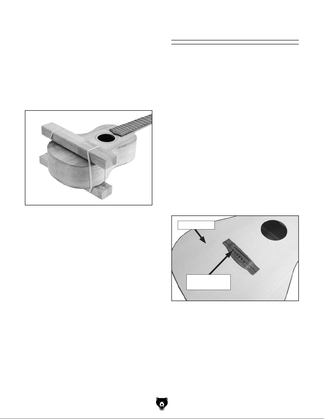
Attaching Bridge With Wood Blocks
If a bridge clamp is not available, it is possible to
successfully mount the bridge with rubber bands
and wood blocks.
1. Follow Steps 1–3 in Attaching Bridge with
Clamp on Page 16.
Carefully position wood blocks over bridge
2.
and under back of guitar, then secure with
rubber bands (see Figure 21).
Fitting Bridge Pins
Now that the bridge is securely attached, it is time
to prepare the bridge for bridge pin fitting.
To protect the finish on the instrument, you should
mask off the top of the guitar around the bridge
before proceeding with these instructions.
Unless otherwise indicated, we strongly recommend using a drill press for the majority of drilling
to obtain the most precise results. However, an
electric/cordless drill fitted with a depth stop or a
drill stand can be used if you do not have a drill
press.
To fit bridge pins:
1. Carefully drill (6) holes in bridge using 5⁄32"
Forstner bit at marked locations (see Figure
22).
Figure 21. Bridge secured with wood blocks.
Make sure to check bridge and verify that it is
3.
still in correct position and adjust if necessary.
Let dry for a minimum of six hours.
4.
5. Remove rubber bands, blocks, and clamps,
and place saddle in position.
Note: Saddle does not need to be glued in.
String tension will keep saddle in place.
Note: Be careful to keep drill straight, and
drill only until you break through the sound
chamber. Do not drill through bottom of guitar.
Sound Board
Bridge Pin Hole
(1 of 6)
Figure 22. Bridge pin locations.
2. Remove debris and sawdust from top and
make sure holes are free of debris.
. Test fit bridge pin.
3
Model T33952/53/54 (Mfd. Since 09/23)
Note: Bridge pin should not fit in hole at this
time.
-17-
Page 20

T-Handle
4. Place T-handle reamer in (1) bridge pin hole,
and gently twist reamer clockwise, making
one complete revolution (see Figure 23).
Note: It is important not to take too much
material out of hole. Bridge pins should be
snug fitting.
3. Gently slide decal off decal sheet into position around sound hole, as shown in Figure
24.
Reamer
Figure 23. Reaming bridge pin hole.
5. Test fit bridge pin in reamed hole.
— If bridge pin does go into hole and fits
snugly, fitting is complete. Proceed to
next hole.
— If bridge pin does not go into hole and
fit snugly, repeat Step 3.
Bridge Pin
Hole
Bridge
Guitar
Body
Guitar
Neck
Figure 24. Sliding decal onto body.
4.
Lightly press down on decal with dampened
fingers and slowly slide decal sheet from
underneath decal (see Figure 25).
Note: As you get closer to fitting bridge pin, it
may be advisable to only rotate reamer
turn. This will avoid removing too much material and having bridge pins that fit too loosely.
1
⁄2
Attaching Sound
Hole Decal
The sound hole decal decorates the guitar and is
easy to attach.
To attach sound hole decal:
1. Submerge decal sheet in water until decal
slides around easily with finger pressure. This
usually only takes a few minutes.
2. Remove decal sheet (with decal) from water,
letting excess water run off.
Figure 25. Pressing decal flat to body.
When decal sheet is completely removed,
5.
lightly press on decal with a dry cloth to
remove excess water trapped underneath.
Let decal dry for at least eight hours.
6.
Installing
Strap Button
The strap button is mounted at the bottom of the
guitar body and acts as an anchor point for a
strap. This installation should be performed after
the finish has been applied to the guitar body.
-18-
Model T33952/53/54 (Mfd. Since 09/23)
Page 21

Button
To install strap button:
1. Locate centerpoint at bottom of instrument
and mark with pencil.
. Drill a hole 3⁄8" deep at marked location.
2
3
. Install strap button with M3 x 20 tap screw
and felt pad, as shown in Figure 26.
2. From back of headstock, slide tuning
machine posts through headstock and seat
(see Figure 27).
Headstock
Tuning Machine Seat
Tuning Machine
Washer
Figure 26. Strap button installed.
Installing Tuning
Machines
The supplied tuning machines are mirrored pairs:
three for the left side of the headstock, three for
the right. Each tuning machine consists of the
parts shown in Figure 27.
Note: Unless otherwise indicated, we recommend
using a drill press for drilling in this manual to
obtain the most precise results. However, an electric/cordless drill fitted with a depth stop or a drill
stand can be used if you do not have a drill press.
Tuning
Machine
Screw
Figure 27. Installing tuning machines.
3. Position tuning machine buttons to outside of
headstock.
4. Set a straightedge across the top of each pair
of machine tuners to ensure they are parallel
with each other from side to side (see Figure
28).
Secure each tuning machine to headstock
5.
with (1) tuning machine screw, as shown in
Figure 28.
Checking
Machine
Tuner
Parallelism
from Side
to Side
Tuning Machine Post
Tuning Machine
x 6
To install tuning machines:
1. Using a non-marring mallet, tap each of (6)
machine seats with washers into pre-drilled
holes on front of headstock.
Note: Install tuners in pairs, from side to side.
Place a straight edge across tops of tuning
machines to ensure they are parallel
(see Figure 27).
Model T33952/53/54 (Mfd. Since 09/23)
Figure 28. Tuning machine components
-19-
Page 22
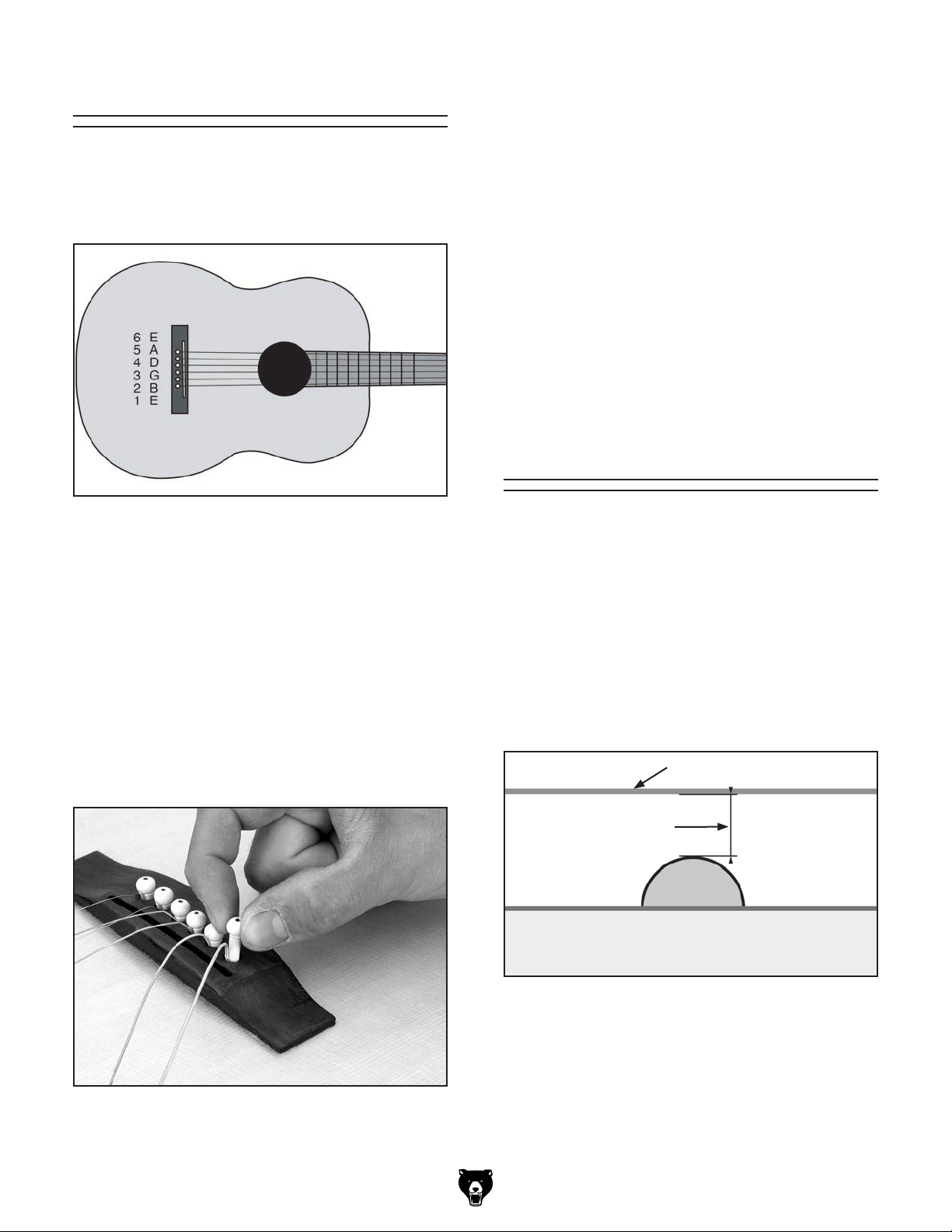
Installing Strings
4. Route string to inside of corresponding tuning
peg and through peg hole.
The correct position of the guitar strings is shown
in Figure 29. The thin High E string is called the
"1st" string and the thick Low E string is called the
"6th" string.
Figure 29. Correct guitar string position.
To install guitar strings:
Insert ball end of string into corresponding
1.
bridge hole.
. Slide a bridge pin over string.
2
Slide bridge pin down string and into bridge
3.
hole (see Figure 30).
Note: Allow enough string slack to complete
2–3 winds around tuning peg.
Turn tuning button counterclockwise to tight-
5.
en string.
Note: DO NOT over-tighten string at this
time. Final string tuning will be discussed
later in manual.
Use wire cutters to cut off excess string.
6.
7. Repeat above process for remaining strings.
Setting String Height
The string height is the distance between the
top of the fret and the bottom of the string
(see Figure 31). Correct string height is crucial for maximizing the playability of the guitar.
Measurements are taken at the 1st and 12th frets.
You can use a variety of tools to check string
heights on guitars, including feeler gauges, a
fine ruler (
gauges, all of which are available at your local
shop or online.
1
⁄64") resolution, and guitar string height
Note: Press bridge pin securely so it will not
come loose under string tuning tension.
Figure 30. Installing strings.
-20-
String
String Height
Fretboard
Figure 31. String height measurement (side view).
Model T33952/53/54 (Mfd. Since 09/23)
Page 23
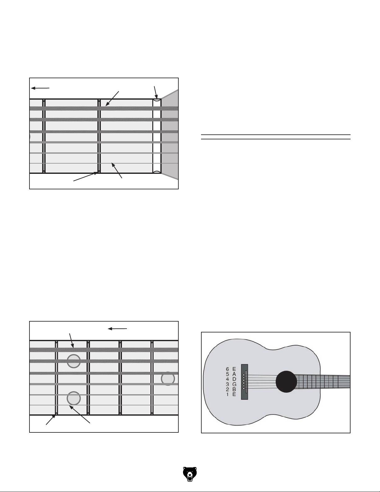
To set string height:
Check string heights of 1st and 6th strings at
1.
1st fret. Measurements should be 1⁄64" at 1st
1
string and
Guitar Body
1st Fret
⁄32" at 6th string (see Figure 32).
Nut
1
6th String:
1st String:
⁄32"
1
⁄64"
Figure 32. Correct 1st fret string heights.
— If string heights are correct, then move to
continue to Tuning on this page.
— If string heights are not correct at 12th fret,
this is an indication that grooves in saddle
need to be adjusted. We recommend having a qualified guitar technician raise or
lower nut before continuing with string
height adjustment at saddle.
Tuning
Tuning is the most important concept of playing a
guitar. If the guitar is not in tune with itself, or the
other instruments in an ensemble, the resulting
music will not sound pleasing to the ear. Having a
good understanding of tuning is essential to maximizing the full potential of any guitar.
— If string heights are correct, then proceed
to Step 2.
— If string heights are not correct at 1st fret,
this is an indication that grooves in string
nut need to be adjusted. We recommend
having a qualified guitar technician raise
or lower nut before continuing with string
height adjustment at 12th fret in next step.
Check string heights of 1st and 6th strings at
2.
12th fret. Measurements should be 3⁄64" at 1st
5
string and
6th String:
⁄64" at 6th string (see Figure 33).
5
⁄64"
Guitar Body
Important issues to consider when tuning a
guitar:
• Get into the habit of tuning the guitar every
time it is picked up to be played.
• Always tune the strings "up." The final tuned
tension of each string should be reached
while tightening the string, not loosening it. If
the string is tensioned too far, loosen the tension and tune "up" again.
• The goal when tuning is to make the strings
in tune with one another. Standard tuning is
shown in Figure 34.
12th Fret
1st String: 3⁄64"
Figure 33. Correct 12th fret string heights.
Model T33952/53/54 (Mfd. Since 09/23)
Figure 34. String tuning notes.
-21-
Page 24

• The easiest way to tune a guitar is using an
electronic tuner. There are a wide variety of
these available in music stores, or online with
a wide variety of prices as well. However, with
practice, you can learn how to tune a guitar
by ear—a skill used by many accomplished
guitar players.
To tune guitar:
Perform same tuning steps on 4th and 3rd
6.
strings.
. When tuning 2nd string, 3rd string should be
7
fretted at 4th fret instead of 5th fret.
Tune 1st string in same manner as 6th, 5th,
8.
4th, and 3rd strings.
1. Play a known Low E pitch. A piano, a tuning
fork, or an electronic computer file will work.
Play an open (non-fretted) 6th string. Goal is
2.
to match open 6th string to known Low E
pitch.
Adjust tuning peg until pitch of open 6th string
3.
sounds exactly like known Low E source.
— If string is tuned too high, back tension off
and return string back up to match Low E
pitch. Now other strings can be tuned to
6th string.
Next, 5th string needs to be tuned. Tone of
4.
5th string must be matched to tone of 6th
string by playing same note on each string,
one after another. This is done by playing 6th
string while it is being pressed (fretted) at 5th
fret, and immediately after, playing open 5th
string.
Listen to two tones. As two notes are still
5.
resonating, adjust tuning peg of 5th string
until two notes have matching tones.
Remember to tune "up."
Guitar Setup
Congratulations—construction of your guitar kit is
now complete!
At this point you may want to consider setting up
the guitar to your own personal specifications.
"Setting up" your guitar can be as simple as swapping out the strings provided to the brand that is
your personal favorite.
Setting up your guitar can also be a bit more
complicated and technical. You can modify or
adjust the guitar to match your preference for not
only strings, but string height, or action, through
nut and saddle adjustments, dialing in truss rod
adjustments, and raising or lowering the bridge,
to name just a few.
There are plenty of resources including books and
websites that will guide you through that process.
It is also possible to have your guitar taken to a
guitar shop or licensed luthier and have them set
up the guitar for you.
Again, congratulations and enjoy your new guitar!
-22-
Model T33952/53/54 (Mfd. Since 09/23)
Page 25
ACCESSORIES
order online at www.grizzly.com or call 1-800-523-4777
SECTION 5: ACCESSORIES
NOTICE
Refer to our website or latest catalog for
additional recommended accessories.
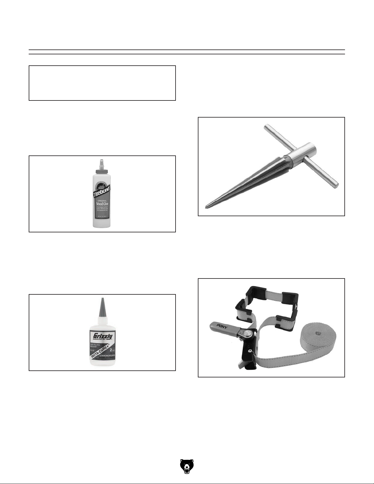
H5332—Titebond Original Wood Glue
The industry standard for general woodworking
applications. Provides strong initial tack and fast
setting speed to reduce clamp time. Develops a
bond stronger than the wood itself.
H5890—Repairman's Taper Reamer.
This Repairman's Taper Reamer reams holes
1
from
for compact storage and 7 flutes for smooth
bores. Reamer measures 5" long. Handle measures 3
⁄8" to 5⁄8" and features a removable handle
1
⁄2 " long.
Figure 35. H5332 Titebond Original Wood Glue.
H0927—Insta-Cure+ 2 oz.
Insta-Cure+ is a powerful CA or Cyanoacrylate
adhesive in a two ounce bottle. Apply to one surface and then hold parts tightly together for about
5 to 15 seconds for a fast, permanent bond.
Figure 36. H0927 Insta-Cure+ 2 oz.
Figure 37. H5890 Repairman's Taper Reamer.
T30674—Pony 15' Band Clamp.
This clamp is ideal for round, irregular or awkwardly-shaped projects. It features 15' of 1" width
high-strength nylon webbing and has a self-locking cam with quick release.
Figure 38. T30674 Pony 15' Band Clamp.
Model T33952/53/54 (Mfd. Since 09/23)
-23-
Page 26

SECTION 6: PARTS
We do our best to stock replacement parts when possible, but we cannot guarantee that all parts shown
are available for purchase. Call (800) 523-4777 or visit www.grizzly.com/parts to check for availability.
1
Main
2
5
10
6 7
11 12
14
3
4
8 9
13
15
16
17 18 19
REF PART # DE S CRIP TI ON REF PART # DE S CRIP TI ON
1 PT33952001 BODY QUILTED MAPLE 10 PT33952010 STRING SET 12-GAUGE
1 PT33953001 BODY FI DDLEBACK MAPLE 11 PT33952011 TUNING MACHINE SEAT
1 PT33954001 BODY KOA 12 PT33952012 TUNING MACHINE WASHER 2MM
2 PT33952002 NECK 13 PT33952013 WOOD SCREW M2 X 9
3 PT33952003 FRETBOARD 14 PT33952014 TUNING MACHINE
4 PT33952004 TRUSS ROD 15 PT33952015 SOUND HOLE DECAL
5 PT33952005 BRIDGE 16 PT33952016 BRIDGE TEMPLATE
6 PT33952006 STRING NUT 17 PT33952017 TAP SCREW M3 X 20
7 PT33952007 SADDLE 18 PT33952018 FELT PAD
8 PT33952008 BRIDGE PIN 19 PT33952019 STRAP BUTTON
9 PT33952009 DOWEL PIN 5 X 19
-24-
BUY PARTS ONLI NE AT GRIZZLY.COM!
Scan QR code to visit our Parts Store.
Model T33952/53/54 (Mfd. Since 09/23)
Page 27

WARRANTY & RETURNS
Grizzly Industrial, Inc. warrants every product it sells for a period of 1 year to the original purchaser from
the date of purchase. This warranty does not apply to defects due directly or indirectly to misuse, abuse,
negligence, accidents, repairs or alterations or lack of maintenance. This is Grizzly’s sole written warranty
and any and all warranties that may be implied by law, including any merchantability or fitness, for any particular purpose, are hereby limited to the duration of this written warranty. We do not warrant or represent
that the merchandise complies with the provisions of any law or acts unless the manufacturer so warrants.
In no event shall Grizzly’s liability under this warranty exceed the purchase price paid for the product and
any legal actions brought against Grizzly shall be tried in the State of Washington, County of Whatcom.
We shall in no event be liable for death, injuries to persons or property or for incidental, contingent, special,
or consequential damages arising from the use of our products.
The manufacturers reserve the right to change specifications at any time because they constantly strive to
achieve better quality equipment. We make every effort to ensure that our products meet high quality and
durability standards and we hope you never need to use this warranty.
In the event you need to use this warranty, contact us by mail or phone and give us all the details. We will
then issue you a “Return Number,’’ which must be clearly posted on the outside as well as the inside of
the carton. We will not accept any item back without this number. Proof of purchase must accompany the
merchandise.
Please feel free to write or call us if you have any questions about the machine or the manual.
Thank you again for your business and continued support. We hope to serve you again soon.
For further information about the
scan the QR
code below
to be automatically directed to our warranty page.
warranty, visit https://www.grizzly.com/forms/warranty or
WARRANTY
Page 28

 Loading...