


MODEL T33926
2/3 HP VARIABLE-SPEED
4-ROLLER POWER FEEDER
OWNER'S MANUAL
(For models manufactured since 08/23)
COPYRIGHT © OCTOBER, 2023 BY GRIZZLY INDUSTRIAL, INC.
WARNING: NO PORTION OF THIS MANUAL MAY BE REPRODUCED IN ANY SHAPE
OR FORM WITHOUT THE WRITTEN APPROVAL OF GRIZZLY INDUSTRIAL, INC.
#JM22825 PRINTED IN TA IWA N
***Keep for Future Reference***
V1.1 0.23

This manual provides critical safety instructions on the proper setup,
operation, maintenance, and service of this machine/tool. Save this
document, refer to it often, and use it to instruct other operators.
Failure to read, understand and follow the instructions in this manual
may result in fire or serious personal injury—including amputation,
electrocution, or death.
The owner of this machine/tool is solely responsible for its safe use.
This responsibility includes but is not limited to proper installation in
a safe environment, personnel training and usage authorization,
proper inspection and maintenance, manual availability and comprehension, application of safety devices, cutting/sanding/grinding tool
integrity, and the usage of personal protective equipment.
The manufacturer will not be held liable for injury or property damage
from negligence, improper training, machine modifications or misuse.
Some dust created by power sanding, sawing, grinding, drilling, and
other construction activities contains chemicals known to the State
of California to cause cancer, birth defects or other reproductive
harm. Some examples of these chemicals are:
• Lead from lead-based paints.
• Crystalline silica from bricks, cement and other masonry products.
• Arsenic and chromium from chemically-treated lumber.
Your risk from these exposures varies, depending on how often you
do this type of work. To reduce your exposure to these chemicals:
Work in a well ventilated area, and work with approved safety equipment, such as those dust masks that are specially designed to filter
out microscopic particles.

Table of Contents
INTRODUCTION............................................................................................................................... 2
Contact Info.................................................................................................................................2
Manual Accuracy.........................................................................................................................2
Identification ................................................................................................................................3
Controls & Components ..............................................................................................................4
Machine Data Sheet....................................................................................................................6
SECTION 1: SAFETY....................................................................................................................... 8
Safety Instructions for Machinery................................................................................................8
Additional Safety for Power Feeders ........................................................................................10
SECTION 2: POWER SUPPLY ...................................................................................................... 11
SECTION 3: SETUP ....................................................................................................................... 13
Unpacking .................................................................................................................................13
Needed for Setup ......................................................................................................................13
Inventory....................................................................................................................................13
Cleanup .....................................................................................................................................14
Site Considerations ...................................................................................................................14
Assembly...................................................................................................................................15
Base Mounting ..........................................................................................................................17
Checking Gearbox Oil Level .....................................................................................................18
Test Run ....................................................................................................................................19
SECTION 4: OPERATIONS ........................................................................................................... 20
Operation Overview ..................................................................................................................20
Basic Use & Care......................................................................................................................21
Changing Speeds......................................................................................................................22
Adjusting Roller Angle ...............................................................................................................22
SECTION 5: ACCESSORIES......................................................................................................... 24
SECTION 6: MAINTENANCE......................................................................................................... 25
Schedule ...................................................................................................................................25
Cleaning & Protecting ...............................................................................................................25
Lubrication.................................................................................................................................25
SECTION 7: SERVICE ................................................................................................................... 28
Troubleshooting.........................................................................................................................28
Replacing Rollers ......................................................................................................................29
SECTION 8: WIRING...................................................................................................................... 30
Wiring Safety Instructions .........................................................................................................30
Wiring Diagram .........................................................................................................................31
SECTION 9: PARTS....................................................................................................................... 32
Main...........................................................................................................................................32
Column & Stand ........................................................................................................................34
Labels & Cosmetics ..................................................................................................................36
WARRANTY & RETURNS ............................................................................................................. 39

We stand behind our machines! If you have questions or need help, contact us with the information
below. Before contacting, make sure you get the
serial number
from the
machine ID label. This will help us help you faster.
We want your feedback on this manual. What did
you like about it? Where could it be improved?
Please take a few minutes to give us feedback.
Email: manuals@grizzly.com
INTRODUCTION
We are proud to provide a high-quality owner’s
manual with your new machine!
We
instructions, specifications, drawings, and photographs
in this manual. Sometimes we make mistakes, but
our policy of continuous improvement also means
that
you receive is
slightly different than shown in the manual
If you find this to be the case, and the difference
between the manual and machine leaves you
confused or unsure about something
check our
website for an updated version. W
current
manuals and
on our web-
site at
Alternatively, you can call our Technical Support
for help. Before calling, make sure you write
down the
serial number
from the machine ID label (see below). This
information is required for us to provide proper
tech support, and it helps us determine if updated
documentation is available for your machine.
Contact Info
and manufacture date
Grizzly Technical Support
1815 W. Battlefield
Springfield, MO 65807
Phone: (570) 546-9663
Email: techsupport@grizzly.com
Grizzly Documentation Manager
P.O. Box 2069
Bellingham, WA 98227-2069
Manual Accuracy
made every effort to be exact with the
sometimes the machine
.
,
e post
manual updates for free
www.grizzly.com.
manufacture date and
Manufacture Date
Serial Number
-2-
Model T33926 (Mfd. Since 08/23)

To reduce your risk of
serious injury, read this
entire manual BEFORE
Identification
Become familiar with the names and locations of the controls and features shown below to better understand
the instructions in this manual.
B
C
A
R
Q
P
D
E
G
F
O
N
H
M
I
J
K
L
A. Horizontal Travel Handwheel
B. Vertical Column
C. Horizontal Travel Lock
D. Upper Elbow-Joint Lock
E. Lower Elbow-Joint Lock
F. Swivel Lock Pin
G. Control Panel
H. Upper Elbow Joint
I. Vertical Travel Crank Handle
Model T33926 (Mfd. Since 08/23)
J. Overarm Shaft
K. Vertical Travel Lock
L. Rotation Lock
M. Rollers
N. Rotation Knob
O. Motor
P. Chain Cover
Q. Lower Elbow-Joint
R. Base
using machine.
-3-

Controls &
To reduce your risk of
serious injury, read this
entire manual BEFORE
Components
using machine.
Refer to the following figures and descriptions to
become familiar with the basic controls and components of this machine. Understanding these
items and how they work will help you understand
the rest of the manual and minimize your risk of
injury when operating this machine.
Control Panel
( )
B. Forward Feed Direction Button
Selects forward feed direction. When pressed,
green light above button illuminates, indicating button is selected. To change feed direction, press feed direction button opposite of
currently selected feed direction twice (2X).
New feed direction will be set at lowest speed
(5 FPM). Press variable-speed adjustment
dial twice to restore original feed rate.
C. SET Button: Enables changes to feed rate.
When pressed, selected feed rate flashes on
control panel for 10 seconds, during which
time feed rate can be selected with variablespeed adjustment dial. When panel stops
flashing, feed rate is locked—until SET button is pressed again.
D. Reverse Feed Direction Button (
Selects reverse feed direction. Green light
below button illuminates, indicating button is
selected.
:
):
A
G
F
Figure 1. Control panel.
A. Variable-Speed Adjustment Dial: Starts
and stops motor and controls feed rate from
5–72 FPM. To start motor, press dial until it
beeps and control panel glows red. To stop
motor, press dial again. To adjust feed rate,
press SET button, then rotate dial clockwise
to increase feed rate or counterclockwise to
decrease feed rate.
B
C
D
E
E. ON/OFF Button: Turns machine ON or OFF.
In ON position, digital readout illuminates.
F. Gearbox Sight Glass: Displays oil level.
G. Feed Speed Digital Readout: Displays feed
rate in feet per minute (FPM).
-4-
Model T33926 (Mfd. Since 08/23)

Power Feeder & Column Controls
L
M
J
H
Figure 2. Location of column controls.
H. Angle Adjustment Scale: Indicates angle
that power feeder assembly is rotated relative
to overarm shaft. Loosen hex bolts on upper
elbow-joint to allow rotation; tighten hex bolts
to secure power feeder angle.
I. Horizontal Travel Lock: Locks horizontal
position of power feeder.
J. Vertical Travel Crank Handle: Adjusts ver-
tical position of overarm shaft and power
feeder (when vertical travel lock is loosened).
K. Vertical Travel Lock: Locks power feeder
height setting.
I
K
N
P
Figure 3. Location of power feeder and column
controls.
L. Horizontal Travel Handwheel: Moves over-
arm shaft horizontally and adjusts lateral
position of power feeder (when horizontal
travel lock (I) is loosened).
M. Upper Elbow-Joint Lock: Allows lower
elbow and power feeder to rotate around
upper elbow. Tighten to secure lower elbow.
N. Lower Elbow-Joint Lock: Allows power
feeder to rotate on its axis when swivel lock
pin is disengaged. Tighten to secure power
feeder swivel position.
O. Swivel Lock Pin: Allows power feeder to
rotate when disengaged. Locks power feeder
in horizontal position when engaged in either
of two detents.
O
Model T33926 (Mfd. Since 08/23)
P. Rotation Lock: Allows vertical column to
rotate when loosened. Prevents vertical column from rotating when tightened.
-5-

MACHINE DATA
SHEET
Customer Service #: (570) 546-9663 · To Order Call: (800) 523-4777 · Fax #: (800) 438-5901
MODEL T33926 2/3 HP VARIABLE‐SPEED 4‐ROLLER POWER
FEEDER
Product Dimensions:
Weight.............................................................................................................................................................. 123 lbs.
Width (side-to-side) x Depth (front-to-back) x Height............................................................... 37-1/2 x 23-1/2 x 30 in.
Footprint (Length x Width)......................................................................................................................... 5-1/2 x 6 in.
Shipping Dimensions:
Carton #1
Type........................................................................................................................................... Cardboard Box
Content................................................................................................................................................. Machine
Weight...................................................................................................................................................... 62 lbs.
Length x Width x Height............................................................................................................ 27 x 13 x 13 in.
Must Ship Upright.......................................................................................................................................... No
Carton #2
Type........................................................................................................................................... Cardboard Box
Content...................................................................................................................................................... Stand
Weight...................................................................................................................................................... 72 lbs.
Length x Width x Height............................................................................................................. 30 x 12 x 12 in.
Must Ship Upright.......................................................................................................................................... No
Electrical:
Power Requirement.......................................................................................................... 220V, Single-Phase, 60 Hz
Full-Load Current Rating....................................................................................................................................... 2.3A
Minimum Circuit Size.............................................................................................................................................. 15A
Connection Type....................................................................................................................................... Cord & Plug
Power Cord Included.............................................................................................................................................. Yes
Power Cord Length............................................................................................................................................ 108 in.
Power Cord Gauge......................................................................................................................................... 18 AWG
Plug Included......................................................................................................................................................... 6-15
Switch Type................................................................................................................................ Push Button ON/OFF
Motors:
Main
Main Specifications:
Workpiece Capacities
-6-
Horsepower............................................................................................................................................. 2/3 HP
Phase............................................................................................................................................ Single-Phase
Amps........................................................................................................................................................... 2.3A
Speed....................................................................................................................................... 350 - 4800 RPM
Type.......................................................................................................................................................... BLDC
Power Transfer .......................................................................................................................................... Gear
Bearings........................................................................................................ Sealed & Permanently Lubricated
Minimum Workpiece Length........................................................................................................................ 6 in.
Model T33926 (Mfd. Since 08/23)

Operation Info
Number of Feed Speeds....................................................................................................................... Variable
Feed Speeds................................................................................................................................... 5 - 72 FPM
Swing.................................................................................................................................................... 360 deg.
Vertical Movement............................................................................................................................. 9-13/16 in.
Horizontal Movement......................................................................................................................... 17-5/16 in.
Rotation................................................................................................................................... Forward/Reverse
Roller Info
Number of Rollers............................................................................................................................................. 4
Roller Width........................................................................................................................................... 2-3/8 in.
Roller Diameter...................................................................................................................................... 4-3/4 in.
Roller Suspension................................................................................................................................. 11/16 in.
Maximum Height Rollers Parallel Table Surface................................................................................... 7-1/2 in.
Construction Info
Roller...................................................................................................................................................... Rubber
Housing...................................................................................................................................... Cast Aluminum
Supports............................................................................................................................................... Cast Iron
Column................................................................................................................................................. Cast Iron
Paint Type/Finish.................................................................................................................................... Enamel
Other
Column Diameter................................................................................................................................... 2-1/4 in.
Other Specifications:
Country of Origin .............................................................................................................................................. Taiwan
Warranty ........................................................................................................................................................... 1 Year
Approximate Assembly & Setup Time ........................................................................................................ 45 Minutes
Serial Number Location .................................................................................................................................. ID Label
ISO 9001 Factory .................................................................................................................................................. Yes
Features:
Variable-Speed Adjustment Dial
Large Feed Speed Digital Readout
Reversible Feed Direction
Crank Handle Vertical Adjustment
Rack-and-Pinion Horizontal Movement
Model T33926 (Mfd. Since 08/23)
-7-

SECTION 1: SAFETY
For Your Own Safety, Read Instruction
Manual Before Operating This Machine
The purpose of safety symbols is to attract your attention to possible hazardous conditions.
This manual uses a series of symbols and signal words intended to convey the level of importance of the safety messages. The progression of symbols is described below. Remember that
safety messages by themselves do not eliminate danger and are not a substitute for proper
accident prevention measures. Always use common sense and good judgment.
Indicates an imminently hazardous situation which, if not avoided,
WILL result in death or serious injury.
Indicates a potentially hazardous situation which, if not avoided,
COULD result in death or serious injury.
Indicates a potentially hazardous situation which, if not avoided,
MAY result in minor or moderate injury. It may also be used to alert
against unsafe practices.
Alerts the user to useful information about proper operation of the
NOTICE
machine to avoid machine damage.
Safety Instructions for Machinery
OWNER’S MANUAL. Read and understand this
owner’s manual BEFORE using machine.
TRAINED OPERATORS ONLY. Untrained operators have a higher risk of being hurt or killed.
Only allow trained/supervised people to use this
machine. When machine is not being used, disconnect power, remove switch keys, or lock-out
machine to prevent unauthorized use—especially
around children. Make your workshop kid proof!
DANGEROUS ENVIRONMENTS. Do not use
machinery in areas that are wet, cluttered, or have
poor lighting. Operating machinery in these areas
greatly increases the risk of accidents and injury.
MENTAL ALERTNESS REQUIRED. Full mental
alertness is required for safe operation of machinery. Never operate under the influence of drugs or
alcohol, when tired, or when distracted.
ELECTRICAL EQUIPMENT INJURY RISKS.
You can be shocked, burned, or killed by touching
live electrical components or improperly grounded
machinery. To reduce this risk, only allow qualified
service personnel to do electrical installation or
repair work, and always disconnect power before
accessing or exposing electrical equipment.
DISCONNECT POWER FIRST.
nect machine from power supply BEFORE making adjustments, changing tooling, or servicing
machine. This prevents an injury risk from unintended startup or contact with live electrical components.
EYE PROTECTION. Always wear ANSI-approved
safety glasses or a face shield when operating
or observing machinery to reduce the risk of eye
injury or blindness from flying particles. Everyday
eyeglasses are NOT approved safety glasses.
Always discon-
-8-
Model T33926 (Mfd. Since 08/23)

WEARING PROPER APPAREL. Do not wear
may damage the wires inside. Do not handle
loose clothing, gloves, neckties, or jewelry that
can become entangled in moving parts. Always tie
back or cover long hair. Wear non-slip footwear to
reduce risk of slipping and losing control or accidentally contacting cutting tool or moving parts.
HAZARDOUS DUST. Dust created by machinery
operations may cause cancer, birth defects, or
long-term respiratory damage. Be aware of dust
hazards associated with each workpiece material. Always wear a NIOSH-approved respirator to
reduce your risk.
HEARING PROTECTION. Always wear hearing protection when operating or observing loud
machinery. Extended exposure to this noise without hearing protection can cause permanent
hearing loss.
REMOVE ADJUSTING TOOLS. Tools left on
machinery can become dangerous projectiles
upon startup. Never leave chuck keys, wrenches,
or any other tools on machine. Always verify
removal before starting!
USE CORRECT TOOL FOR THE JOB. Only use
this tool for its intended purpose—do not force
it or an attachment to do a job for which it was
not designed. Never make unapproved modifications—modifying tool or using it differently than
intended may result in malfunction or mechanical
failure that can lead to personal injury or death!
AWKWARD POSITIONS. Keep proper footing
and balance at all times when operating machine.
Do not overreach! Avoid awkward hand positions
that make workpiece control difficult or increase
the risk of accidental injury.
CHILDREN & BYSTANDERS. Keep children and
bystanders at a safe distance from the work area.
Stop using machine if they become a distraction.
GUARDS & COVERS. Guards and covers reduce
accidental contact with moving parts or flying
debris. Make sure they are properly installed,
undamaged, and working correctly BEFORE
operating machine.
FORCING MACHINERY. Do not force machine.
It will do the job safer and better at the rate for
which it was designed.
NEVER STAND ON MACHINE. Serious injury
may occur if machine is tipped or if the cutting
tool is unintentionally contacted.
STABLE MACHINE. Unexpected movement during operation greatly increases risk of injury or
loss of control. Before starting, verify machine is
stable and mobile base (if used) is locked.
USE RECOMMENDED ACCESSORIES. Consult
this owner’s manual or the manufacturer for rec-
ommended accessories. Using improper accessories will increase the risk of serious injury.
UNATTENDED OPERATION. To reduce the
risk of accidental injury, turn machine OFF and
ensure all moving parts completely stop before
walking away. Never leave machine running
while unattended.
MAINTAIN WITH CARE. Follow all maintenance
instructions and lubrication schedules to keep
machine in good working condition. A machine
that is improperly maintained could malfunction,
leading to serious personal injury or death.
DAMAGED PARTS. Regularly inspect machine
for damaged, loose, or mis-adjusted parts—or
any condition that could affect safe operation.
Immediately repair/replace BEFORE operating
machine. For your own safety, DO NOT operate
machine with damaged parts!
MAINTAIN POWER CORDS. When disconnecting cord-connected machines from power, grab
and pull the plug—NOT the cord. Pulling the cord
cord/plug with wet hands. Avoid cord damage by
keeping it away from heated surfaces, high traffic
areas, harsh chemicals, and wet/damp locations.
EXPERIENCING DIFFICULTIES. If at any time
you experience difficulties performing the intended operation, stop using the machine! Contact our
Technical Support at (570) 546-9663.
Model T33926 (Mfd. Since 08/23)
-9-

Additional Safety for Power Feeders
Serious injury or death can occur from getting hands, clothing, or jewelry entangled in moving
parts of power feeder or being pulled into cutting tool on attached machinery. Workpieces
ejected by attached machine can strike operator or bystanders with significant force, causing
impact injuries. To minimize risk of injury, anyone operating this machine MUST completely
heed hazards and warnings below.
HAND SAFETY. To reduce risk of accidental
entanglement/pinch injuries between power feeder rollers and workpiece, or contact with blade/cutter of associated machine, keep hands away from
rotating parts of power feeder. Turn power feeder
and associated machine OFF before removing
chips, sawdust, or cutoffs—DO NOT use your
hands.
INSTALLING GUARDS. To reduce risk of kickback and accidental contact with blade/cutter
of associated machine, always install guards,
fences, and hold-downs before starting attached
machine and power feeder. Repair or replace
guards promptly if they become damaged.
KICKBACK. Occurs when workpiece is ejected
from machine at a high rate of speed. To reduce
risk of kickback-related injuries (blindness, broken
bones, bruises, amputation, severe lacerations,
and death), use quality workpieces and proper
setup or maintenance of power feeder or associated machine. Never stand in path of workpiece.
VERIFY EACH SETUP. An improperly adjusted
power feeder can increase risk of kickback,
because it will continue feeding even if stock is
not properly positioned for cut. Ensure that power
feeder is set up correctly and firmly secured
before feeding workpiece.
FEATHERBOARD. When cutting long or large
stock that is difficult to feed properly, use a featherboard with power feeder (on the infeed side) to
maintain even pressure and control of workpiece
against fence, and to help reduce risk of kickback.
FEED WORKPIECE PROPERLY. To reduce risk
of kickback, verify blade or cutter of associated
machine is at full speed before feeding stock
with power feeder. Avoid feeding workpiece too
quickly. Always verify power feeder wheels are
slightly lower than workpiece to ensure it will not
slip during cutting operation. Stop power feeder
BEFORE stopping cutting tool.
WORKPIECE SUPPORT. Loss of workpiece control while feeding can increase risk of kickback.
Support workpiece continuously during operation as required. Use auxiliary stands or support
tables for long or wide stock.
ADJUSTMENTS/MAINTENANCE. Make sure
power feeder and associated machine are turned
OFF, disconnected from power, and all moving
parts are completely stopped before doing adjustments or maintenance.
ATTACHED MACHINERY. Follow all warnings
and safety information for attached machine doing
cutting work.
Like all machinery there is potential danger
when operating this machine. Accidents
are frequently caused by lack of familiarity
or failure to pay attention. Use this machine
with respect and caution to decrease the
risk of operator injury. If normal safety precautions are overlooked or ignored, serious personal injury may occur.
-10-
No list of safety guidelines can be complete. Every shop environment is different.
Always consider safety first, as it applies
to your individual working conditions. Use
this and other machinery with caution and
respect. Failure to do so could result in
serious personal injury, damage to equipment, or poor work results.
Model T33926 (Mfd. Since 08/23)

SECTION 2: POWER SUPPLY
Before installing the machine, consider the availability and proximity of the required power supply
circuit. If an existing circuit does not meet the
requirements for this machine, a new circuit must
be installed. To minimize the risk of electrocution,
fire, or equipment damage, installation work and
electrical wiring must be done by an electrician or
qualified service personnel in accordance with all
applicable codes and standards.
or equipment damage
may occur if machine is
not properly grounded
and connected to power
The full-load current rating is the amperage a
machine draws at 100% of the rated output power.
On machines with multiple motors, this is the
amperage drawn by the largest motor or sum of all
motors and electrical devices that might operate
at one time during normal operations.
The full-load current is not the maximum amount
of amps that the machine will draw. If the machine
is overloaded, it will draw additional amps beyond
the full-load rating.
If the machine is overloaded for a sufficient length
of time, damage, overheating, or fire may result—
especially if connected to an undersized circuit.
To reduce the risk of these hazards, avoid overloading the machine during operation and make
sure it is connected to a power supply circuit that
meets the specified circuit requirements.
For your own safety and protection of
Note: Circuit requirements in this manual apply to
a dedicated circuit—where only one machine will
be running on the circuit at a time. If machine will
be connected to a shared circuit where multiple
machines may be running at the same time, consult an electrician or qualified service personnel to
ensure circuit is properly sized for safe operation.
A power supply circuit includes all electrical
equipment between the breaker box or fuse panel
in the building and the machine. The power supply circuit used for this machine must be sized to
safely handle the full-load current drawn from the
machine for an extended period of time. (If this
machine is connected to a circuit protected by
fuses, use a time delay fuse marked D.)
This machine is prewired to operate on a power
supply circuit that has a verified ground and meets
the following requirements:
Availability
Electrocution, fire, shock,
supply.
Full-Load Current Rating
Circuit Information
property, consult an electrician if you are
unsure about wiring practices or electrical
codes in your area.
Full-Load Current Rating at 220V .... 2.3 Amps
Model T33926 (Mfd. Since 08/23)
Circuit Requirements
Nominal Voltage ......... 208V, 2 2 0V, 230V, 2 4 0V
Cycle ..........................................................60 Hz
Phase ........................................... Single-Phase
Power Supply Circuit ......................... 15 Amps
Plug/Receptacle ............................. NEMA 6 -15
-11-
Improper connection of the equipment-grounding
wire can result in a risk of electric shock. The
wire with green insulation (with or without yellow
stripes) is the equipment-grounding wire. If repair
or replacement of the power cord or plug is necessary, do not connect the equipment-grounding
wire to a live (current carrying) terminal.
Check with a qualified electrician or service personnel if you do not understand these grounding
requirements, or if you are in doubt about whether
the tool is properly grounded. If you ever notice
that a cord or plug is damaged or worn, disconnect it from power, and immediately replace it with
a new one.
We do not recommend using an extension cord
with this machine.
cord, only use it if absolutely necessary and only
on a temporary basis.
Extension cords cause voltage drop, which can
damage electrical components and shorten motor
life. Voltage drop increases as the extension cord
size gets longer and the gauge size gets smaller
(higher gauge numbers indicate smaller sizes).
Any extension cord used with this machine must
be in good condition and contain a ground wire
and matching plug/receptacle. Additionally, it must
meet the following size requirements:
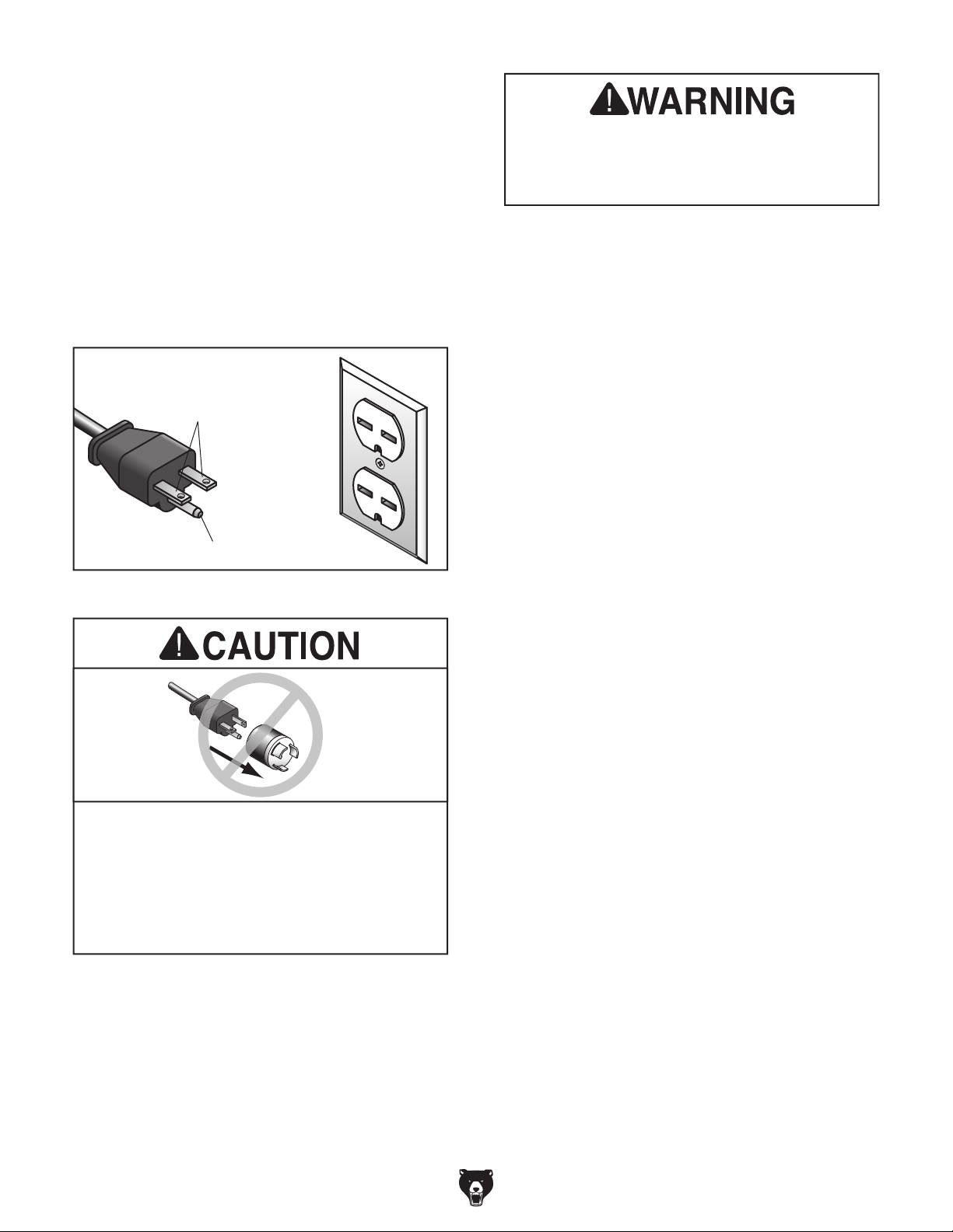
Grounding Requirements
This machine MUST be grounded. In the event
of certain malfunctions or breakdowns, grounding
reduces the risk of electric shock by providing a
path of least resistance for electric current.
This machine is equipped with a power cord that
has an equipment-grounding wire and a grounding
plug. Only insert plug into a matching receptacle
(outlet) that is properly installed and grounded in
accordance with all local codes and ordinances.
DO NOT modify the provided plug!
No adapter should be used with plug. If
process. DO NOT connect to power until
GROUNDED
6-15 RECEPTACLE
Current Carrying Prongs
6-15 PLUG
Serious injury could occur if you connect
machine to power before completing setup
instructed later in this manual.
Grounding Pin
Figure 4. Typical 6-15 plug and receptacle.
plug does not fit available receptacle, or if
machine must be reconnected for use on a
different type of circuit, reconnection must
be performed by an electrician or qualified
service personnel, and it must comply with
all local codes and ordinances.
-12-
Extension Cords
If you must use an extension
Minimum Gauge Size ...........................18 AWG
Maximum Length (Shorter is Better).......50 ft.
Model T33926 (Mfd. Since 08/23)

SECTION 3: SETUP
This machine was carefully packaged for safe
transport. When unpacking, separate all enclosed
items from packaging materials and inspect them
for shipping damage.
,
please
IMPORTANT:
you are completely satisfied with the machine and
have resolved any issues between Grizzly or the
shipping agent. You MUST have the original pack-
aging to file a freight claim. It is also extremely
helpful if you need to return your machine later.
The following items are needed, but not included,
for the setup/assembly of this machine.
Unpacking
If items are damaged
call us immediately at (570) 546-9663.
Save all packaging materials until
If any non-proprietary parts are missing (e.g. a
nut or a washer), we will gladly replace them; or
for the sake of expediency replacements can be
obtained at your local hardware store.
Box 1 (Figure 5) Qty
A. Power Feeder Assembly ............................ 1
B. Lower Elbow-Joint ...................................... 1
C. Base Bolt Pattern Template........................ 1
D. Indicator Sticker.......................................... 1
E. Angle Adjustment Scale ............................. 1
F. Rotation Knob M10-1.5 ............................... 1
Needed for Setup
Description Qty
• Safety Glasses (for each person)............... 1
• Cleaner/Degreaser .................... As Needed
• Shop Rags.................................. As Needed
• Disposable Gloves ..................... As Needed
• Hex Wrench 4, 5, 8mm ........................1 Ea.
• Phillips Head Screwdriver #2 ..................... 1
• C-Clamps ................................................... 2
• 12" 2x4 Wood Block................................... 1
• Open-End Wrench 12, 14mm,
• Power Drill .................................................. 1
• Drill Bit & Tap ............................................. 1
• Optional Mounting Hardware...... As Needed
• Thread Locking Fluid.................. As Needed
• Gear Oil (80-90W)...................... As Needed
11
⁄16 " ......1 Ea.
A
F
Box 2 (Figure 6) Qty
G. Vertical Column Assembly ......................... 1
H. Overarm Shaft ............................................ 1
I. Hex Bolts M12-1.75 x 50 (Mounting)........... 4
J. Lock Washers 12mm (Mounting)................ 4
K. Vertical Travel Crank Handle...................... 1
L. Upper Elbow-Joint...................................... 1
G
E
Figure 5. Box 1 inventory.
L
Figure 6. Box 2 inventory.
B
D
K
C
H
I
J
The following is a list of items shipped with your
machine. Before beginning setup, lay these items
out and inventory them.
Model T33926 (Mfd. Since 08/23)
Inventory
NOTICE
If you cannot find an item on this list, carefully check around/inside the machine and
packaging materials. Often, these items get
lost in packaging materials while unpacking or they are pre-installed at the factory.
-13-

Cleanup
The unpainted surfaces of your machine are
coated with a heavy-duty rust preventative that
prevents corrosion during shipment and storage.
This rust preventative works extremely well, but it
will take a little time to clean.
Be patient and do a thorough job cleaning your
machine. The time you spend doing this now will
give you a better appreciation for the proper care
of your machine's unpainted surfaces.
There are many ways to remove this rust preventative, but the following steps work well in a wide
variety of situations. Always follow the manufacturer’s instructions with any cleaning product you
use and make sure you work in a well-ventilated
area to minimize exposure to toxic fumes.
Before cleaning, gather the following:
• Disposable rags
• Cleaner/degreaser (WD•40 works well)
• Safety glasses & disposable gloves
• Plastic paint scraper (optional)
Basic steps for removing rust preventative:
1.
2. Coat the rust preventative with a liberal
amount of cleaner/degreaser, then let it soak
3.
scrape off as much as you can first, then wipe
4.
then coat all unpainted surfaces with a quality
Refer to the Machine Data Sheet for the weight
and footprint specifications of your machine.
Some workbenches may require additional reinforcement to support the weight of the machine
and workpiece materials.
or disable start switch or
Consider anticipated workpiece sizes and additional space needed for auxiliary stands, work
tables, or other machinery when establishing a
location for this machine in the shop. Below is
the minimum amount of space needed for the
Site Considerations
Workbench Load
Placement Location
37½"
23½"
Put on safety glasses.
for 5–10 minutes.
Wipe off the surfaces. If your cleaner/degreas-
er is effective, the rust preventative will wipe
off easily. If you have a plastic paint scraper,
off the rest with the rag.
Repeat Steps 2–3 as necessary until clean,
metal protectant to prevent rust.
NOTICE
Avoid harsh solvents like acetone or brake
parts cleaner that may damage painted surfaces. Always test on a small, inconspicuous location first.
-14-
Figure 7. Minimum working clearances.
Note: Power feeder can rotate 360° around the
vertical column, so be sure to situate machine so
it can freely rotate. The machine is shown here
with the overarm shaft fully extended.
Children and visitors may be
seriously injured if unsupervised around this machine.
Lock entrances to the shop
power connection to prevent
unsupervised use.
Model T33926 (Mfd. Since 08/23)
Assembly
The machine must be fully assembled before it
can be operated. Before beginning the assembly
process, refer to
and gather
all
To ensure the assembly process
goes smoothly, first clean any
covered or coated in heavy-duty rust preventative (if
applicable).
listed items.
Needed for Setup
parts that are
Tip: We recommend using a set of C-clamps to
temporarily secure the base while assembling the
power feeder to prevent it from tipping. You will
mount the power feeder to the machine table after
completing the assembly process. Refer to Base
Mounting on Page 17 for specific details.
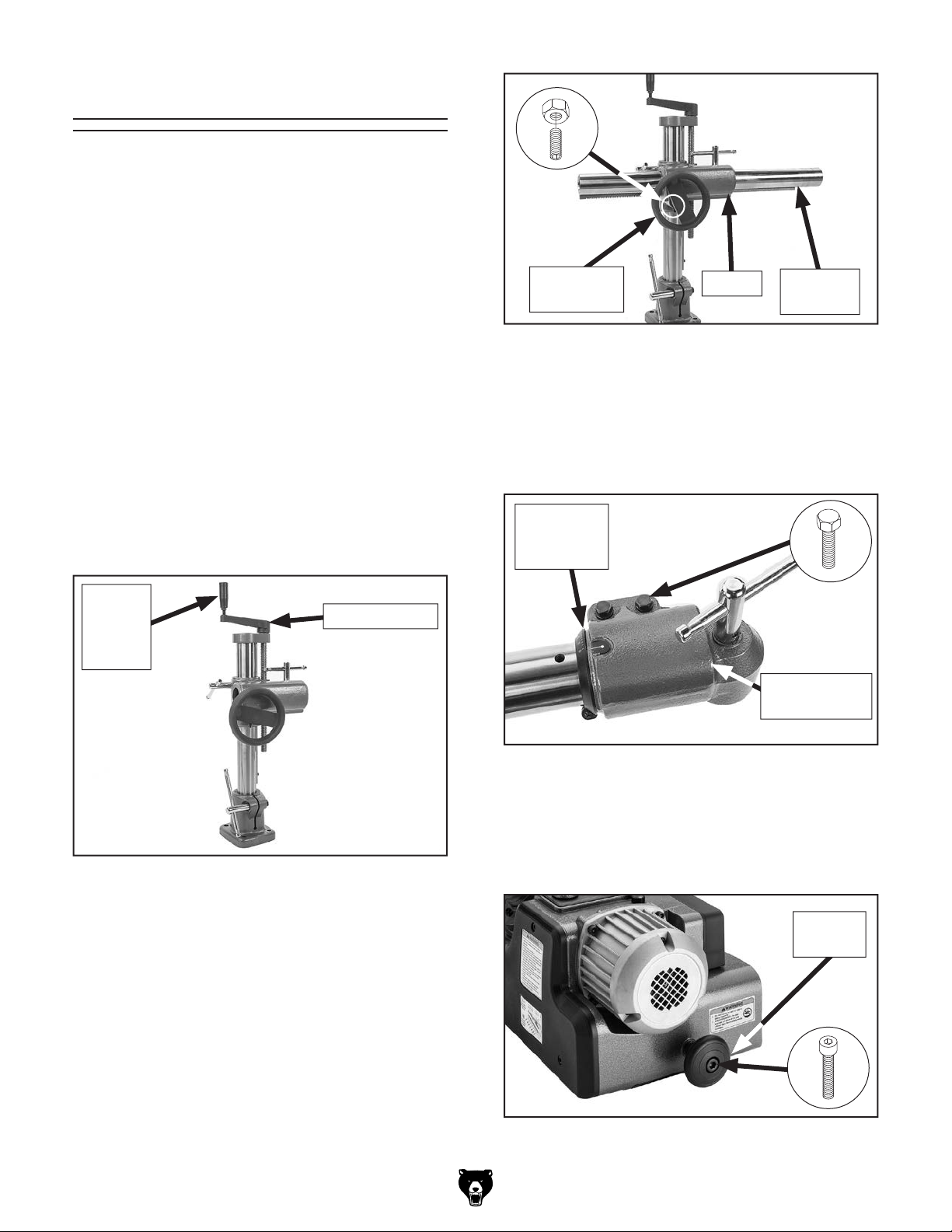
To assemble machine:
1. Place vertical column assembly onto machine
table top, then attach vertical travel crank
handle to vertical crank shown in Figure 8.
Vertical
Travel
Crank
Handle
Vertical Crank
Horizontal
Handwheel
Figure 9. Overarm shaft installed onto vertical
4. Slide angle adjustment scale onto overarm
shaft, slide upper elbow-joint onto overarm
shaft, then secure for now by tightening one
of the hex bolts shown in Figure 10.
Angle
Adjustment
Scale
Sleeve
column.
Overarm
Shaft
x 2
Upper Elbow-
Joint
Figure 8. Vertical travel crank handle installed.
2. Loosen hex nut and set screw under hori-
zontal handwheel shown in Figure 9, then
remove horizontal handwheel.
3. Feed overarm shaft into sleeve of vertical
column (see Figure 9). Re-install handwheel
and engage gears with overarm shaft teeth.
Tighten set screw and hex nut just enough to
secure handwheel.
Note: Do not overtighten set screw or handwheel will not rotate.
Model T33926 (Mfd. Since 08/23)
Figure 10. Angle adjustment scale installed onto
upper elbow-joint.
5. Attach rotation knob to power feeder
(see Figure 11) using pre-installed cap
screw, flange nut, and (2) flat washers.
Rotation
Knob
Figure 11. Rotation knob installed.
-15-

6. Thread lower elbow-joint lever all the way
into threads of axial hub on power feeder
(see Figure 12).
8. Position upper elbow-joint so internal threads
contact those inside lower elbow-joint, then
fully tighten upper elbow-joint lock (see Figure
14).
Lower
Elbow-Joint
Lever
Axial Hub
Figure 12. Example of attaching lower elbow-
joint.
7. Loosen vertical and horizontal travel locks and
rotation lock, then use horizontal handwheel
and vertical travel handle to position upper
elbow-joint directly over hub of lower elbowjoint (see Figure 13).
Tip: Place a short (approx. 12" long) 2x4
under power feeder to make it level with table
top and make it easier to connect upper and
lower elbow-joints during next step.
Upper
Elbow-Joint
Upper
Elbow-Joint
Lock
Figure 14. Upper elbow-joint lock fully tightened.
9. Adjust rollers parallel to table top, then tight-
en hex bolts shown in Figure 15.
10. Remove backing from indicator line sticker
and install in recess on upper elbow-joint, as
shown in Figure 15.
11. Position angle adjustment scale so it just
contacts upper elbow-joint, align "0" on
scale with indicator line, then tighten screw
(see Figure 15).
Indicator
Line
Sticker
Rotation
Lock
Figure 13. Aligning upper and lower elbow-
joints.
-16-
Lower
Elbow-
Joint
2x4
"0"
Angle
Adjustment
Scale
Figure 15. Angle adjustment scale and indicator
line sticker installed.
Model T33926 (Mfd. Since 08/23)
Base Mounting
Position the power feeder on the table top to
determine where to drill the base mounting holes
in order to maximize power feeder swing and
adjustment options.
Use the included base bolt pattern template to
align the mounting holes. Consider the available
mounting choices for your needs: Through-Bolt
Mounting and Direct Mounting (discussed on
Page 18).
With either mounting choice, leave room to operate the hand cranks and lock levers to position the
rubber rollers parallel with the table surface and
approximately
workpiece.
1
⁄8" lower than the thickness of the
Also, aim the front of the power feeder slightly
towards the machine fence (see Figure 16)
with approximately 1° to 1.5° toe-in toward the
machine fence, so the rubber rollers lightly push
the workpiece against the fence during cutting
operations.
If cutting long or large stock that is difficult to feed
properly, use a featherboard before the power
feeder (on the infeed side) to maintain even pressure and control of the workpiece against the
fence.
4-Roller
Models
Table SawShaper
Blade
Feed
Feed
Cutter
Fence
Jointer
Feed
Cutterhead
Optional
Featherboard
Fence
Figure 16. Typical power feed mounting on a shaper, jointer, and table saw.
Fence
Model T33926 (Mfd. Since 08/23)
-17-
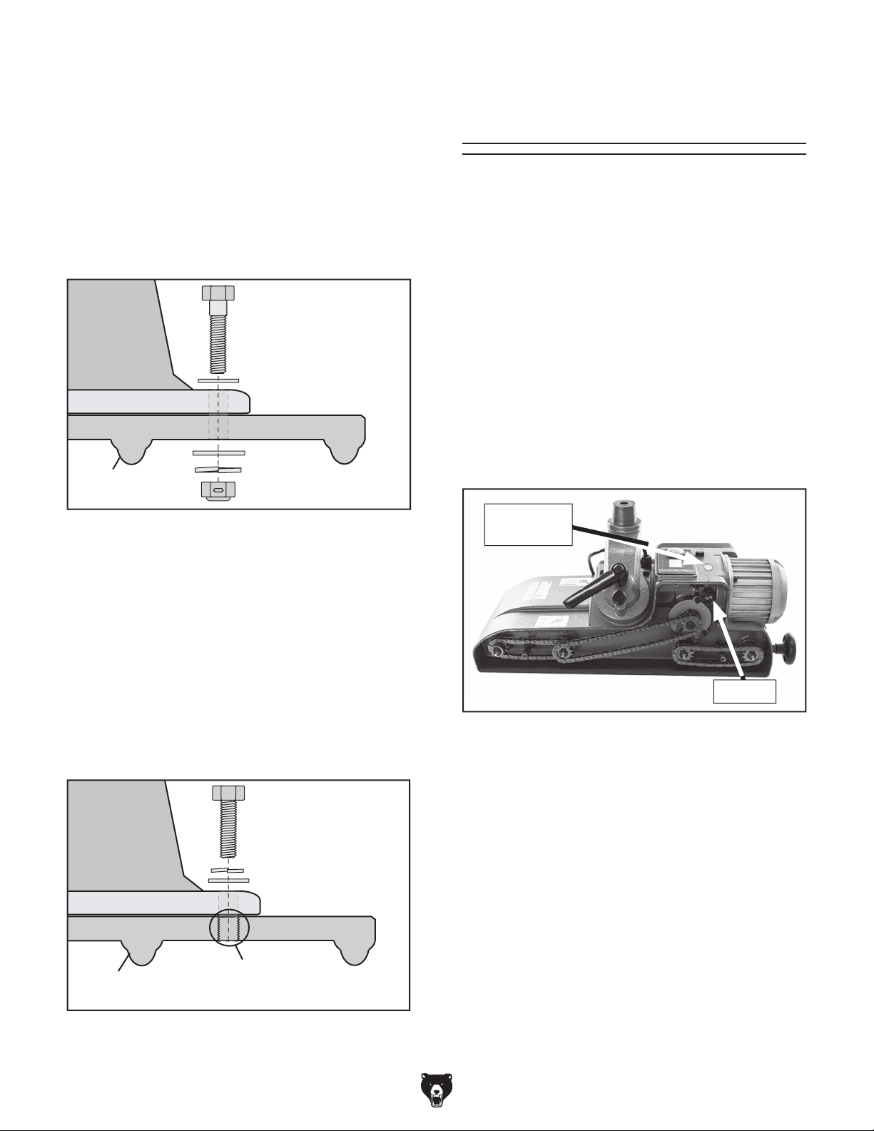
Through-Bolt Mounting
We recommend mounting the power feeder to the
machine table with through bolts, nuts, and washers (see Figure 17). This provides the most rigidity and clamping strength to prevent the feeder
base from twisting out of alignment during use.
However, if under-table support webs interfere
with washer or nut locations, drill and thread holes
directly into the table (Direct Mounting). Use the
included mounting template as a guide.
Feeder
Base
Bolt
Flat Washer
Checking Gearbox
Oil Level
Before starting the machine for the first time,
check the oil level in the gearbox. The gearbox
has the proper amount of oil when the sight glass
is filled approximately halfway. DO NOT mix oil
types.
Items Needed Qty
Hex Wrench 5mm.............................................. 1
Gear Oil 80-90W ............................... As Needed
To check gearbox oil level:
1. Rotate machine so chain cover is facing up.
Machine Table
Flat Washer
Table Support
Webbing
Lock Washer
Locking Hex Nut
Figure 17. Through-bolt mounting.
Direct Mounting
Use the included mounting template to drill and tap
the table so the power feeder base can be directly
mounted to the table surface (see Figure 18). Use
medium-grade liquid thread-locking compound on
all threads. If the table is less than
the holes will be drilled and tapped, or if support
webbing interferes, the threads may strip or loosen during power feeder use. Thread-locking compound is not a permanent solution. Revert to the
Through-Bolt Mounting or clamping kit options.
Feeder
Base
Bolt
Lock Washer
Flat Washer
3
⁄8" thick where
2. Locate gearbox sight glass beneath control
panel (see Figure 19).
Gearbox
Sight Glass
Oil Plug
Figure 19. Oil plug and gearbox sight glass
locations.
— If sight glass is filled approximately halfway,
then gearbox oil level is okay. Proceed to
Test Run.
— If sight glass is not filled approximately
halfway, then you need to add more oil.
Proceed to Step 3.
Machine Table
Table Support
Webbing
-18-
Apply Medium Grade
Thread-Locking Compound
Figure 18. Direct mounting.
3. Remove chain cover.
4. Remove oil plug (see Figure 19) and add
gear oil until sight glass is filled approximately
halfway, then replace oil plug.
5. Install chain cover and rotate power feeder
back into position for operation.
Model T33926 (Mfd. Since 08/23)

Test Run
Once assembly is complete, test run the machine
to ensure it is properly connected to power and
safety components are functioning correctly.
If you find an unusual problem during the test run,
immediately stop the machine, disconnect it from
power, and fix the problem BEFORE operating the
machine again. The
table in the
SERVICE section of this manual can help.
DO NOT start machine until all preceding
setup instructions have been performed.
Operating an improperly set up machine
ed results that can lead to serious injury,
Serious injury or death can result from
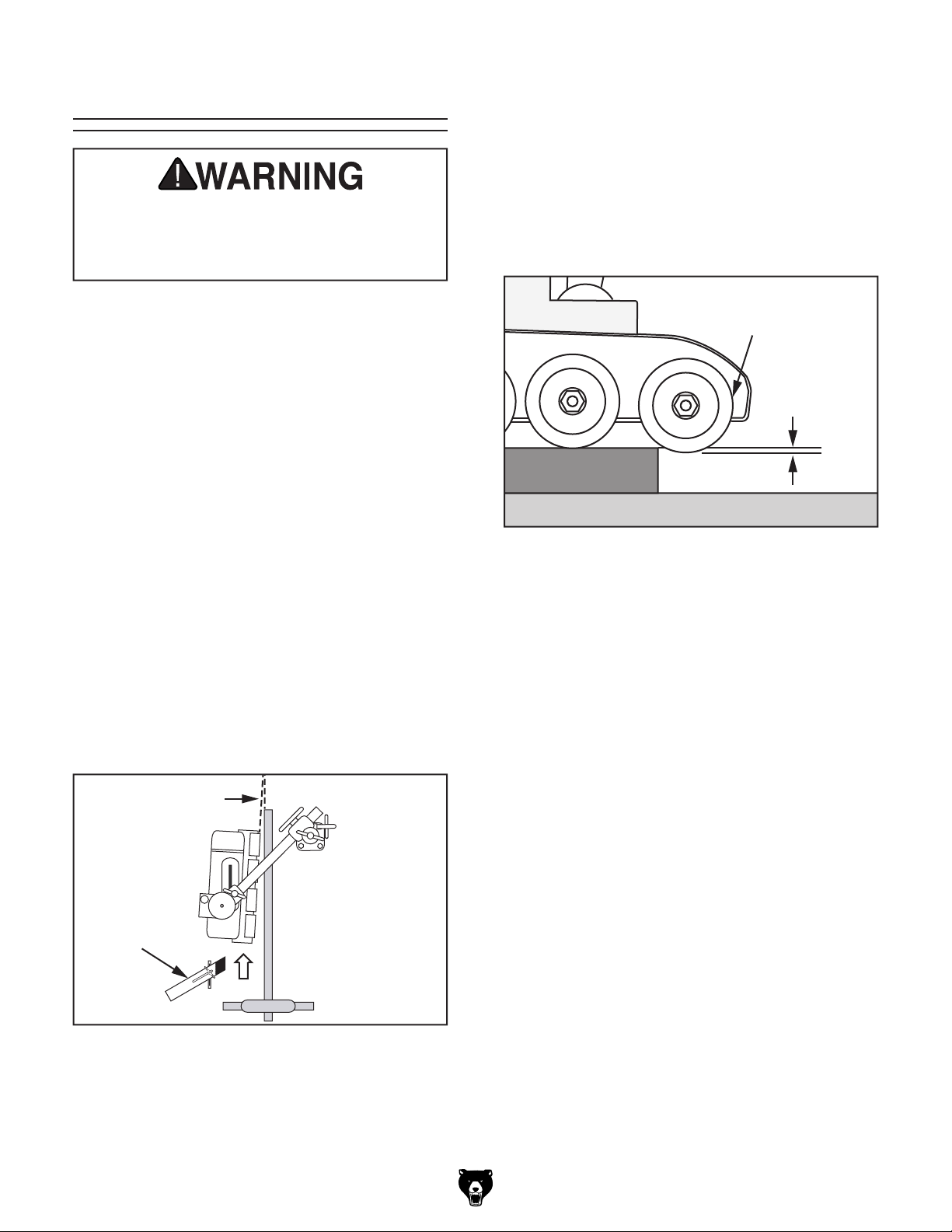
To test run machine:
1. Clear all setup tools away from machine.
2. Adjust and lock power feeder so rollers are
held approximately 1" above machine table
and nothing will interfere with roller rotation.
3. Connect power feeder to power supply.
Troubleshooting
The Test Run consists of verifying the following:
1) The motor powers up and runs correctly, and
2) the control panel works correctly.
using this machine BEFORE understanding
its controls and related safety information.
DO NOT operate, or allow others to operate,
machine until the information is understood.
may result in malfunction or unexpect-
death, or machine/property damage.
4. Press ON/OFF button. Digital readout will
illuminate.
5. Press SET button, and use variable-speed
adjustment dial to select 10 FPM on readout.
Number will flash for 10 seconds, then glow
steadily.
6. Press forward feed direction button
), then press and hold variable-speed
(
adjustment dial until you hear a beeping sound
and outside edge of panel glows red. Motor
should run smoothly and without unusual
problems or noises. Rollers should rotate in a
counterclockwise direction (when viewed from
top).
— If motor or rollers do not function cor-
rectly, disconnect from power and refer to
Troubleshooting on Page 28 before
completing Test Run.
7. Press variable-speed adjustment dial. Rollers
should stop rotating.
For the following Test Run steps, refer to Figure 20.
Readout
Variable-
Speed
Adjustment
Dial
Figure 20. Readout illuminated.
Model T33926 (Mfd. Since 08/23)
ON/OFF
Button
Forward
Direction
Reverse
Direction
Feed
Button
Set
Button
Feed
Button
— If rollers stop rotating, variable-speed
adjustment dial is functioning correctly.
Proceed to Step 8.
— If rollers do not stop rotating, variable-
speed adjustment dial is NOT functioning correctly. Contact Grizzly Technical
Support before proceeding with Test Run.
8. Press reverse feed direction button
), then press and hold variable-speed
(
adjustment dial until you hear a beep and
control panel glows red. Rollers should rotate
in clockwise direction (when viewed from top).
9. Press variable-speed adjustment dial to stop
rollers.
Test Run is complete.
-19-

SECTION 4: OPERATIONS
The purpose of this overview is to provide the novice machine operator with a basic understanding
of how the machine is used during operation, so
the
discussed later
in this manual
Due to the generic nature of this overview, it is
not intended to be an instructional guide. To learn
more about specific operations, read this entire
manual,
training from experienced
machine operators
outside of this manual by reading "how-to" books,
trade magazines, or websites.
To reduce your risk of
serious injury, read this
entire manual BEFORE
To reduce risk of eye injury from flying
Operation Overview
To complete a typical operation, the operator
does the following:
1. Examines workpiece to make sure it is suit-
able for cutting operation.
machine controls/components
are easier to understand.
seek additional
, and do additional research
using machine.
2. Adjusts machine cutter/blade and fence for
desired operation.
3. Checks outfeed side of machine for proper
support and to make sure workpiece can
safely pass all the way through cutter/blade
without interference.
4. Loosens upper elbow-joint lock and points
power feeder 1° to 1.5° toward machine
fence, so rollers will lightly push workpiece
against fence during cutting operations, then
tightens elbow-joint lock.
5. Loosens vertical travel lock and lower elbow-
joint lock, then adjusts position of power feeder so rollers are parallel with table surface
1
⁄8" lower than thickness of workpiece,
and
then tightens all locks.
6. Checks to make sure rollers are clear of cut-
ter or blade.
chips or lung damage from breathing dust,
always wear safety glasses and a respirator
when operating this machine.
If you are not experienced with this type
of machine, WE STRONGLY RECOMMEND
that you seek additional training outside of
this manual. Read books/magazines or get
formal training before beginning any projects. Regardless of the content in this section, Grizzly Industrial will not be held liable
for accidents caused by lack of training.
-20-
7. (Optional) positions featherboard on infeed
side for cutting long or large stock that is difficult to feed properly.
8. Sets feed speed and direction using control
panel.
9. Puts on safety glasses and a respirator.
10. Starts machine, then starts power feeder.
Feeds stock into power feeder, maintaining
firm pressure on workpiece against table and
fence.
11. Stops power feeder, then stops machine.
Model T33926 (Mfd. Since 08/23)
Basic Use & Care
You MUST assemble all guards, fences, and
hold-downs before starting your machine or
power feeder. Failure to heed this warning
could result in amputation or death!
Next, adjust power feeder so the rollers are parallel
with the table surface and approximately
than the thickness of the workpiece, as shown in
Figure 22. This ensures that the workpiece will
not slip or hang during a cut. Always double check
that the power feeder rollers are always slightly
lower than the workpiece before you begin feeding operations. Otherwise, the workpiece may slip
and kick back.
1
⁄8" lower
Power feeders reduce kickback hazards and
improve cutting results by feeding in a consistent
and stable manner. Remember, DO NOT stand in
the path of potential kickback. When not in use,
support the power feeder with a wooden block so
the rollers are raised above the table and do not
compress from the weight of the power feeder.
The lock levers and hand cranks allow you to
adjust the power feeder tracking and height to
accommodate many workpiece sizes. Before
loosening any lock lever, always support the
power feeder with a block of wood so the power
feeder does not drop and cause damage.
Adjust the power feeder so it is toed-in approximately 1° to 1.5° towards the machine fence, as
shown in Figure 21. This adjustment will ensure
that the power feeder rollers slightly push the
workpiece against the fence during cutting operations. Use a featherboard on the infeed side to
assist with feeding long or large stock.
Roller
Approx. 1/8"
Workpiece
Machine Table
Figure 22. Roller adjusted approximately
below workpiece.
1
⁄8"
1° to 1.5° Angle
Optional
Featherboard
Feed
Figure 21. Example of power feeder toe-in on
table saw.
Model T33926 (Mfd. Since 08/23)
-21-

Changing Speeds
To reduce risk of shock or
accidental startup, always
disconnect machine from
power before adjustments,
maintenance, or service.
Adjusting Roller
Angle
The Model T33926 can be positioned to feed
workpieces so the rollers are angled relative to
the machine fence from 45°–90°. For example, it
can be positioned at 90° to feed stock against a
fence, or positioned at 45° for making bevel cuts
on a jointer.
Variable-Feed Speeds.................... 5 – 72 FPM
Users can change the feed rate by adjusting the
variable-speed adjustment dial on the control
panel.
To change speed:
1. Press SET button on control panel, as shown
in Figure 23.
Note: Current feed rate will flash for up to
10 seconds, after which SET button must be
pressed again to adjust feed rate.
Use the controls shown in Figure 24 to position
the power feeder for incline feeding.
Upper Elbow-
Joint Lock
x 2
Lower
Elbow-Joint
Lock
Rotation
Lock
Figure 24. Location of controls for re-positioning
power feeder for incline feeding.
SET
Variable-Speed
Adjustment Dial
Figure 23. Location of SET button and variable-
speed adjustment dial on control panel.
2. Rotate variable-speed adjustment dial to
desired feed rate.
-22-
Button
Tools Needed Qty
Open-End Wrench or Socket 14mm ................. 1
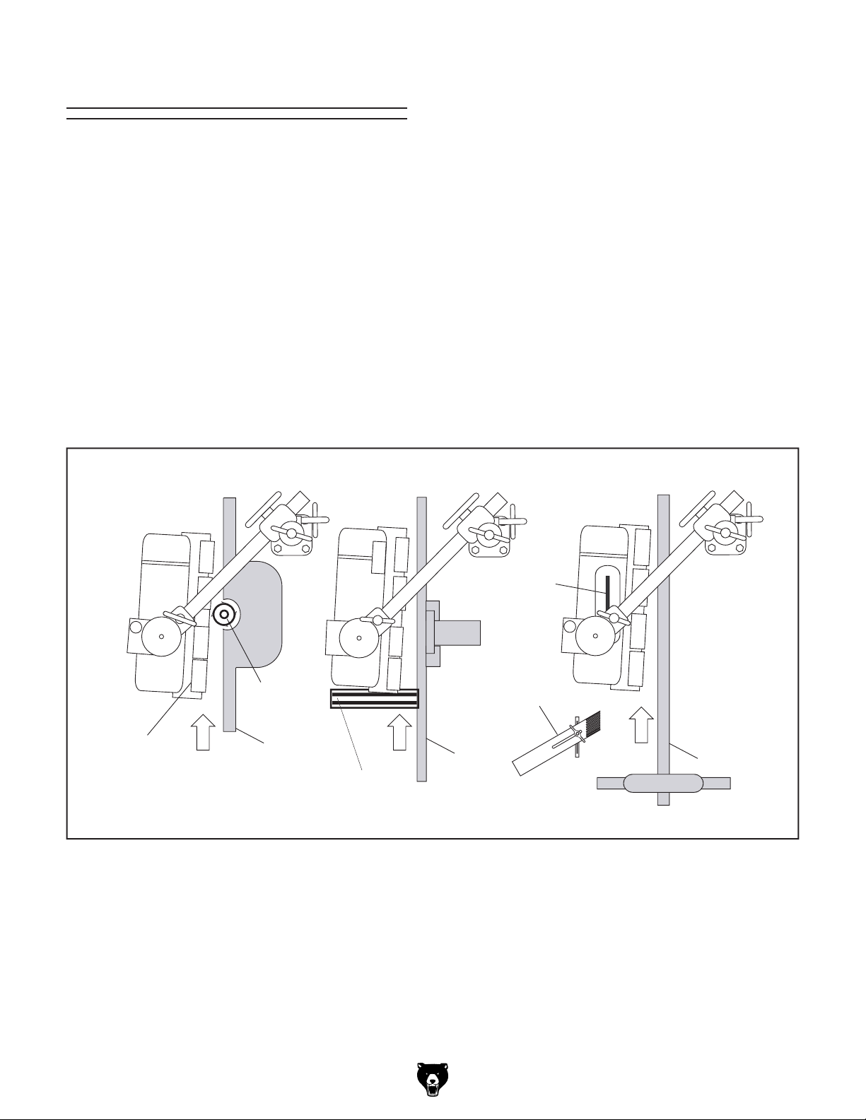
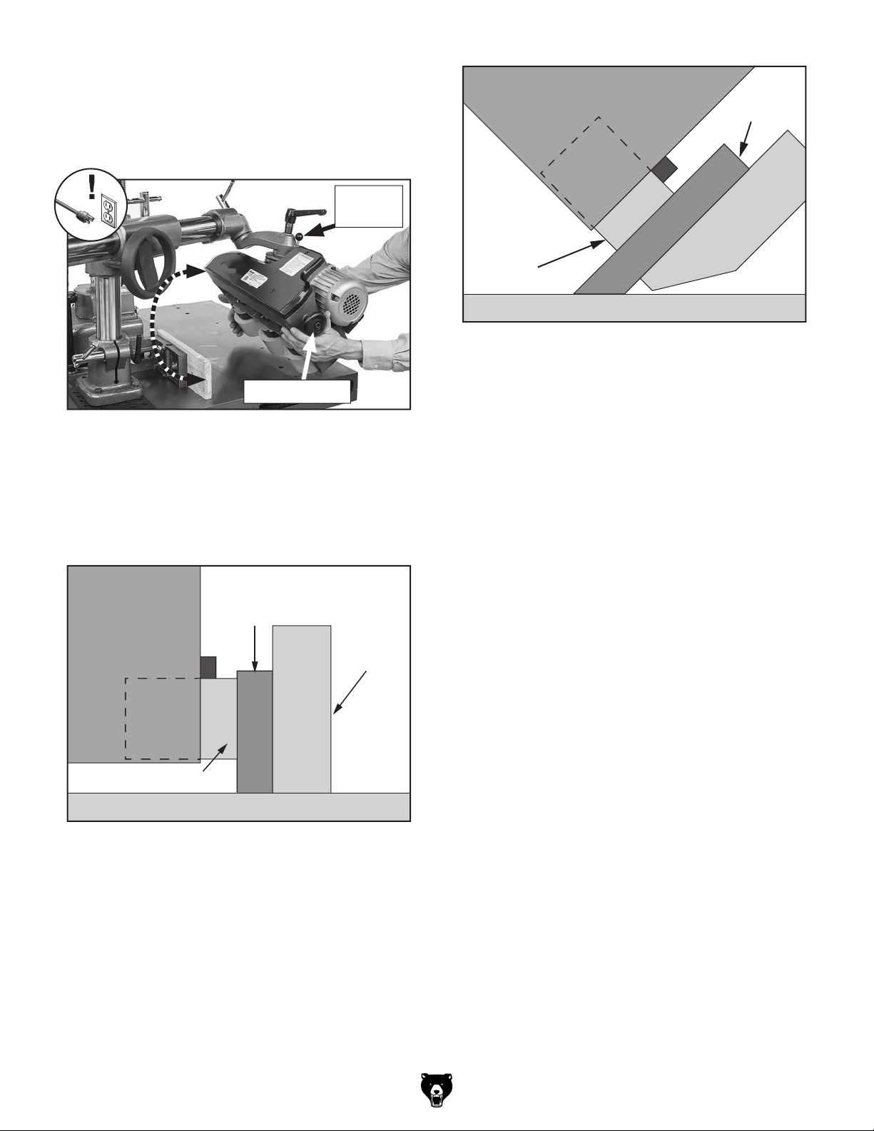
To position power feeder for vertical/incline
feeding:
1. DISCONNECT MACHINE FROM POWER!
2. Loosen rotation lock (see Figure 24) and
swing power feeder off of machine table.
3. Loosen (2) hex bolts on upper elbow-joint,
rotate upper elbow to desired angle, then
tighten hex bolts (see Figure 24) to secure
setting.
4. Loosen upper elbow-joint lock and lower
elbow-joint lock (see Figure 24).
Model T33926 (Mfd. Since 08/23)
5. While holding onto rotation knob with one
hand, disengage swivel lock pin, rotate power
feeder clockwise (flip it upside down) so it is
oriented as shown in Figure 25, then move it
back over table and up against fence.
Swivel
Lock Pin
(Side View)
Power
Feeder
Power
Feeder
Wheel
Table
Figure 27. Example of power feeder set up for
45° feeding operation on jointer.
Workpiece
Jointer
Fence
at 45º
Rotation Knob
Figure 25. Example of rotating power feeder for
vertical or incline feeding.
6. Lower power feeder and adjust it as needed
so rollers are parallel with workpiece and
workpiece is firmly against fence, as shown
in Figures 26–27.
(Side View)
Power
Feeder
Power Feeder Roller
Workpiece
Fence
7. Tighten all locks on power feeder and vertical
column.
8. Repeat Steps 2–7 in reverse order to reposition power feeder for non-angle feeding
operations.
Table
Figure 26. Example of power feeder set up for
90° feeding operation on shaper against a fence.
Model T33926 (Mfd. Since 08/23)
-23-

ACCESSORIES
Installing unapproved accessories may
order online at www.grizzly.com or call 1-800-523-4777
SECTION 5: ACCESSORIES
cause machine to malfunction, resulting in
serious personal injury or machine damage.
To reduce this risk, only install accessories
recommended for this machine by Grizzly.
NOTICE
Refer to our website or latest catalog for
additional recommended accessories.
T28172—14" x 39" Heavy-Duty Roller Table
T28 3 69 —14" x 78" Heavy-Duty Roller Table
T28 370 —14" x 118" Heavy-Duty Roller Table
Increase material handling and processing efficiency with one or more of these Heavy-Duty
Roller Tables. Ideal for easily positioning material
for cross cutting or cutting to length using a chop
saw or metal cutting bandsaw. Simply place a
roller table on one or both sides of your saw and
production time is automatically improved!
T26419—Syn-O-Gen Synthetic Grease
Formulated with 100% pure synthesized hydrocarbon basestocks that are compounded with special
thickeners and additives to make Syn-O-Gen
non-melt, tacky, and water resistant. Extremely
low pour point, extremely high temperature oxidation, and thermal stability produce a grease that is
unmatched in performance.
Figure 29. Recommended product for machine
lubrication.
T33985—Replacement Roller for T33926
These 2
made from synthetic rubber and fit the T33926.
3
⁄8" wide x 43⁄4" diameter rollers are
Figure 30. T33985 Replacement Roller.
Figure 28. Heavy-duty roller tables.
-24-
Model T33926 (Mfd. Since 08/23)

SECTION 6: MAINTENANCE
To reduce risk of shock or
accidental startup, always
disconnect machine from
power before adjustments,
maintenance, or service.
Schedule
For optimum performance from this machine, this
maintenance schedule must be strictly followed.
Ongoing
To minimize your risk of injury and maintain proper
machine operation, shut down the machine immediately if you ever observe any of the items below,
and fix the problem before continuing operations:
• Loose mounting bolts.
• Damaged rollers.
• Worn or damaged switch, cord, and plug.
• Any other unsafe condition.
Every 8 Hours of Operation
• Check gearbox oil level (Page 18).
• Lubricate chains and sprockets
(Page 26).
• Lubricate vertical travel leadscrew
(Page 27).
• Lubricate lock levers (Page 27).
• Lubricate overarm rack (Page 27).
Monthly Maintenance
• Lubricate roller and chain grease fittings
(Page 26).
• Change gearbox oil—after first month
(Page 26).
Every 6 Months
• Change gearbox oil (Page 26).
Model T33926 (Mfd. Since 08/23)
Cleaning &
Protecting
Cleaning the Model T33926 is relatively easy.
Frequently blow off sawdust with compressed air.
This is especially important for internal working
parts and the motor. Dust build-up around the
motor will decrease its lifespan. If rollers become
loaded up with pitch, oil, or other residues, wipe
with a clean rag and soap and water. Keep mineral spirits away from plastic parts or painted surfaces to avoid damage.
Lubrication
Other than the lubrication points covered in this
section, all other bearings are internally lubricated
and sealed at the factory. Simply leave them
alone unless they need to be replaced.
Before performing any lubrication task,
DISCONNECT MACHINE FROM POWER!
IMPORTANT: Before adding lubricant, clean any
debris and grime from fill hole/grease fitting and
immediate area to prevent contamination of new
lubricant.
Use the schedule below and the following instructions to properly lubricate the other components
that require lubrication.
Frequency
Lubrication Task
Roller & Chain Grease
Fittings
Gearbox 1000 Hrs.
Chains & Sprockets 8 Hrs.
Vertical Travel Leadscrew 8 Hrs.
Lock Levers 8 Hrs.
Overarm Rack 8 Hrs.
(Hours of
Operation)
200 Hrs.
Page
Ref.
26
26
27
27
27
28
-25-
Items Needed Qty
NLGI#2 Grease or Equivalent ........... As Needed
ISO 32 Oil or Equivalent.................... As Needed
80-90W Gear Oil ............................... As Needed
Clean Shop Rags .............................. As Needed
Mineral Spirits.................................... As Needed
Brushes ............................................. As Needed
1-Gallon Catch Pan ........................................... 1
Grease Gun
Hex Wrench 5mm.............................................. 1
1
⁄8" NPT ......................................... 1
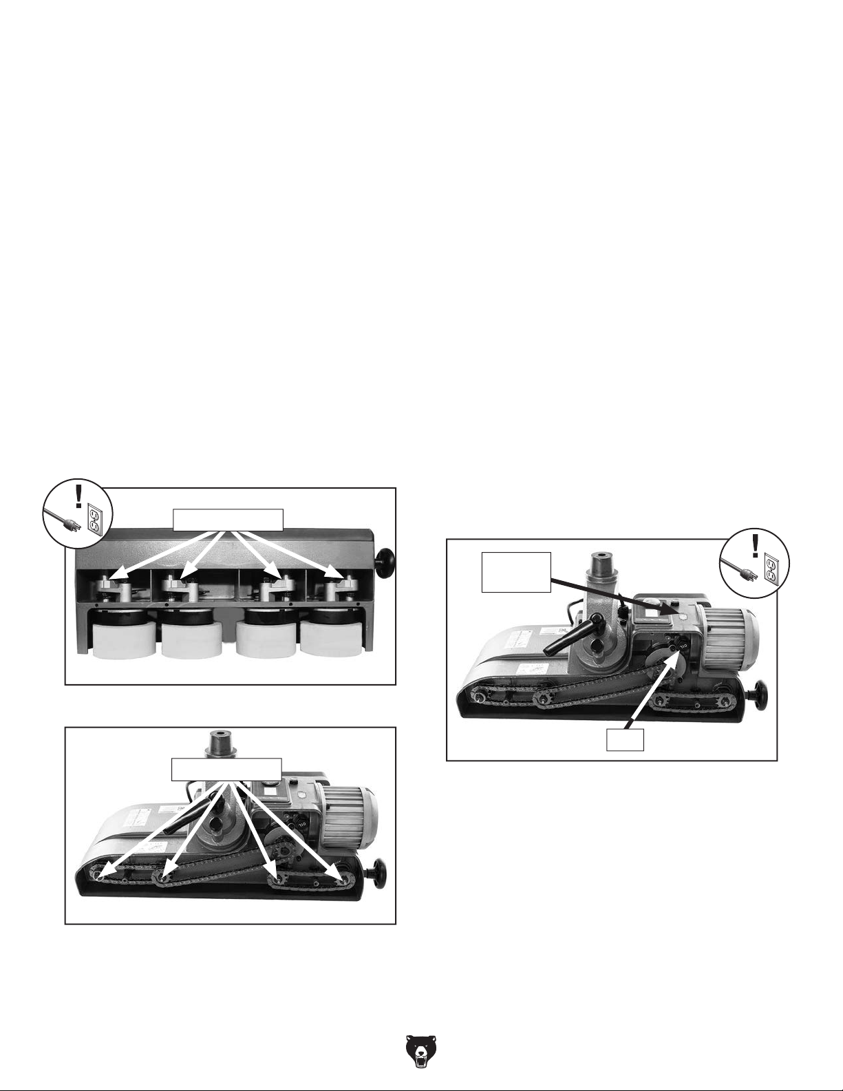
Roller & Chain Grease Fittings
Lube Type............. T26419 or NLGI#2 Equivalent
Amount ................................................ 1–2 Pump
Lubrication Frequency .......200 Hrs. of Operation
Grease Gun ....................................................... 1
Wipe the roller and chain grease fittings clean and
lubricate with one pump from a grease gun filled
with NLGI#2 grease (see Figures 31–32). It will
be necessary to remove the chain cover to access
the chain grease fittings.
Grease Fittings
Gearbox
Lube Type.................................80-90W Gear Oil
Amount ...................................................4.05 Oz.
Lubrication Frequency:
• 200 Hrs./First Month of Operation
• 1000 Hrs./6 Months of Operation
The gearbox should be drained and refilled after
the first month or 200 hours of use. For the
remaining life of the power feeder, change oil
every six months or 1000 hours of use.
To change gearbox oil:
1. DISCONNECT MACHINE FROM POWER!
2. Rotate power feeder off of machine table,
remove chain cover, and tighten rotation lock.
3. Rotate power feeder upside down so chains
face down.
4. Place drain pan under plug labeled "OIL,"
then remove plug (see Figure 33) and drain
oil.
Figure 31. Location of roller grease fittings.
Grease Fittings
Figure 32. Location of chain grease fittings
(chain cover removed).
Oil Sight
Glass
Plug
Figure 33. Location of gearbox plug/oil drain and
sight glass.
5. Rotate power feeder 180 degrees so chains
are facing up, fill gearbox with oil until oil level
is at halfway point in sight glass, then replace
plug.
6. Install chain cover and rotate power feeder
back into position for operation.
-26-
Model T33926 (Mfd. Since 08/23)

Chains & Sprockets
Lube Type............. T26419 or NLGI#2 Equivalent
Amount .................................................Thin Coat
Lubrication Frequency ...........8 Hrs. of Operation
Lock Levers
Lube Type........................... ISO 32 or Equivalent
Amount .................................................Thin Coat
Lubrication Frequency ...........8 Hrs. of Operation
Use mineral spirits to clean any debris and builtup grime. To prevent rust and binding, brush the
sprockets and chains (see Figure 34) with a light
film of NLGI#2 grease. It will be necessary to
remove the chain cover to access the chain and
sprockets.
Sprockets
Chains
Figure 34. Location of chain and sprockets (chain
cover removed).
Vertical Travel Leadscrew
Lube Type............. T26419 or NLGI#2 Equivalent
Amount .................................................Thin Coat
Lubrication Frequency ...........8 Hrs. of Operation
Use mineral spirits to clean any debris and builtup grime. Brush a thin coat of lubricant on the
threads of the leadscrew (see Figure 35), then
rotate leadscrew through its full path to distribute
the grease.
To prevent rust and binding, periodically clean
and oil all lock-lever and leadscrew threads
(see Figure 36) with light machine oil.
Figure 36. Location of levers to lubricate.
Overarm Rack
Lube Type............. T26419 or NLGI#2 Equivalent
Amount .................................................Thin Coat
Lubrication Frequency ...........8 Hrs. of Operation
Clean the overarm rack teeth (see Figure 37) with
mineral spirits, shop rags, and a brush. When dry,
use a brush to apply a thin coat of grease to the
teeth, then move the overarm back and forth several times to distribute the grease.
Vertical
Travel
Leadscrew
Figure 35. Vertical travel leadscrew.
Model T33926 (Mfd. Since 08/23)
Overarm
Rack
Figure 37. Overarm rack teeth.
-27-

Review the troubleshooting procedures in this section if a problem develops with your machine. If you need
the
serial number and manufacture date of your machine before calling.
SECTION 7: SERVICE
replacement parts or additional help with a procedure, call our Technical Support. Note: Please gather
Troubleshooting
Motor & Electrical
Symptom Possible Cause Possible Solution
Motor does not
start, or power
supply breaker
immediately
trips upon
startup.
Machine
stalls or is
underpowered.
Machine has
vibration or
noisy operation.
Error message
on control
panel (E1, E2,
E3).
1. Blown fuse.
2. Incorrect power supply voltage or circuit size.
3. Power supply circuit breaker tripped or fuse
blown.
4. Wiring broken, disconnected, or corroded.
5. ON/OFF button at fault.
6. Circuit board at fault.
7. Motor or motor bearings at fault.
1. Workpiece crooked; fence loose or
misadjusted.
2. Gearbox at fault.
3. Circuit board at fault.
4. Pulley/sprocket slipping on shaft.
5. Motor overheated.
6. Extension cord too long.
7. Motor or motor bearings at fault.
1. Motor or component loose.
2. Incorrectly mounted.
3. Workpiece loose.
4. Rollers protruding unevenly.
5. Motor bearings at fault.
1. (E1) Motor failed to start; workpiece jammed.
2. (E2) Circuit board temperature too high.
3. (E3) Motor temperature too high.
1. Replace fuse/ensure no shorts.
2. Ensure correct power supply voltage and circuit size
(Pa ge 11).
3. Ensure circuit is free of shorts. Reset circuit breaker or
replace fuse.
4. Fix broken wires or disconnected/corroded
connections (Page 30).
5. Replace ON/OFF button.
6. Inspect/replace if at fault.
7. Replace motor.
1. Straighten or replace workpiece/adjust fence.
2. Replace broken or slipping gears.
3. Inspect/replace if at fault.
4. Tighten/replace loose pulley/shaft.
5. Clean motor, let cool, and reduce workload.
6. Move machine closer to power supply; use shorter
extension cord.
7. Replace motor.
1. Replace damaged or missing bolts/nuts or tighten if
loose.
2. Adjust or tighten mounting hardware.
3. Move rollers closer to workpiece (Page 22).
4. Adjust rollers.
5. Test by rotating shaft; rotational grinding/loose shaft
requires bearing replacement.
1. Remove jammed workpiece.
2. Allow circuit board to cool.
3. Allow motor to cool.
Operations
Symptom Possible Cause Possible Solution
Workpiece
jams when
feeding under
rollers.
-28-
1. Rollers positioned too low.
2. Feeder at wrong angle.
1. Raise feeder (Page 21).
2. Adjust angle (Page 22).
Model T33926 (Mfd. Since 08/23)

Operations (Cont.)
accidental startup, always
disconnect machine from
Symptom Possible Cause Possible Solution
Workpiece slips
while passing
beneath rollers.
Rough finish or
chipped grain
on workpiece.
Workpiece cut
is burnt.
Workpiece
hangs up and
does not enter
the machine.
1. Rollers positioned too high.
2. Workpiece too dusty.
3. Rollers dirty or oily.
4. Feed speed too fast.
5. Worn roller(s).
6. Rollers loose.
1. Feed speed too fast.
2. Dull cutter or blade.
3. Power feeder angle not toed-in to keep
workpiece against fence.
1. Feed speed too slow.
2. Dull cutter or blade.
1. Rollers positioned too high. 1. Lower power feeder rollers
Replacing Rollers
1. Lower power feeder rollers
workpiece (Page 21).
2. Wipe dust off workpiece.
3. Clean roller surface with soap and warm water.
4. Reduce feed speed (Page 22).
5. Replace roller(s) (Page 29).
6. Tighten roller fasteners (Page 29).
1. Reduce feed speed (Page 22).
2. Replace with sharp cutter or blade.
3. Adjust power feeder so it is toed in 1° to 1.5° toward
fence (Page 22).
1. Increase feed speed (Page 22).
2. Install sharp cutter or blade.
workpiece (Page 21).
2. Remove hex nut and washer that secure
roller (see Figure 38).
1
⁄8" lower than height of
1
⁄8" lower than height of
To reduce risk of shock or
power before adjustments,
maintenance, or service.
Over time, the rubber rollers will wear down or
become damaged. When this occurs, they can be
easily replaced.
Items Needed Qty
9
Socket
⁄16".......................................................... 1
Socket Wrench .................................................. 1
Replacement Rollers (Model T33985).. As Needed
To replace roller:
1. DISCONNECT MACHINE FROM POWER!
Figure 38. Roller hex nut location.
3. Remove and replace roller.
4. Install hex nut and washer and tighten.
Model T33926 (Mfd. Since 08/23)
-29-

These pages are current at the time of printing. However, in the spirit of improvement, we may make changes to the electrical systems of future machines. Compare the manufacture date of your machine to the one
number and manufacture date of your
machine before calling. This information can be found on the main machine label.
machine
SECTION 8: WIRING
stated in this manual, and study this section carefully.
If there are differences between your machine and what is shown in this section, call Technical Support at
(570) 546-9663 for assistance BEFORE making any changes to the wiring on your machine. An updated
wiring diagram may be available. Note: Please gather the serial
Wiring Safety Instructions
SHOCK HAZARD. Working on wiring that is con-
nected to a power source is extremely dangerous.
Touching electrified parts will result in personal
injury including but not limited to severe burns,
electrocution, or death. Disconnect the power
from the machine before servicing electrical components!
MODIFICATIONS. Modifying the wiring beyond
what is shown in the diagram may lead to unpredictable results, including serious injury or fire.
This includes the installation of unapproved aftermarket parts.
WIRE CONNECTIONS. All connections must
be tight to prevent wires from loosening during
machine operation. Double-check all wires disconnected or connected during any wiring task to
ensure tight connections.
CIRCUIT REQUIREMENTS. You MUST follow
the requirements at the beginning of this manual
when connecting your machine to a power source.
WIRE/COMPONENT DAMAGE. Damaged wires
or components increase the risk of serious personal injury, fire, or machine damage. If you notice
that any wires or components are damaged while
performing a wiring task, replace those wires or
components.
MOTOR WIRING. The motor wiring shown in
these diagrams is current at the time of printing
but may not match your machine. If you find this
to be the case, use the wiring diagram inside the
motor junction box.
CAPACITORS/INVERTERS. Some capacitors
and power inverters store an electrical charge for
up to 10 minutes after being disconnected from
the power source. To reduce the risk of being
shocked, wait at least this long before working on
capacitors.
EXPERIENCING DIFFICULTIES. If you are experiencing difficulties understanding the information
included in this section, contact our Technical
Support at (570) 546-9663.
The photos and diagrams
included in this section are
best viewed in color. You
can view these pages in
color at www.grizzly.com.
-30-
Model T33926 (Mfd. Since 08/23)

Wiring Diagram
6-15 Plug
J011240
CN1
220V
BLDC Motor
L1
L2
U
V
W
GND
GND
Fuses
L1
8A 250V
8A 250V
L2
L3
Circuit Board
J011238-1
GND
C1
JACKCON
F
200V
CN1
Pu
RS485
JACKCON
DC310
Circuit Board
BT-220-RT-V1
CN2
F1
F2
C2
F
200V
W
W
L1
L2
DC IN
+
CN2
U
V
V
U
-
-
ON/OFF
Button
Finglai R16-503AD
+
Digital Readout
L1
L2
ON
L1
L2
L2
L1
1
2
Ground
Pu
G
Hot
220
VAC
Hot
Figure 39. Motor circuit board wiring. Figure 40. Digital readout circuit board.
Model T33926 (Mfd. Since 08/23)
READ ELECTRICAL SAFETY
ON PAGE 30!
-31-
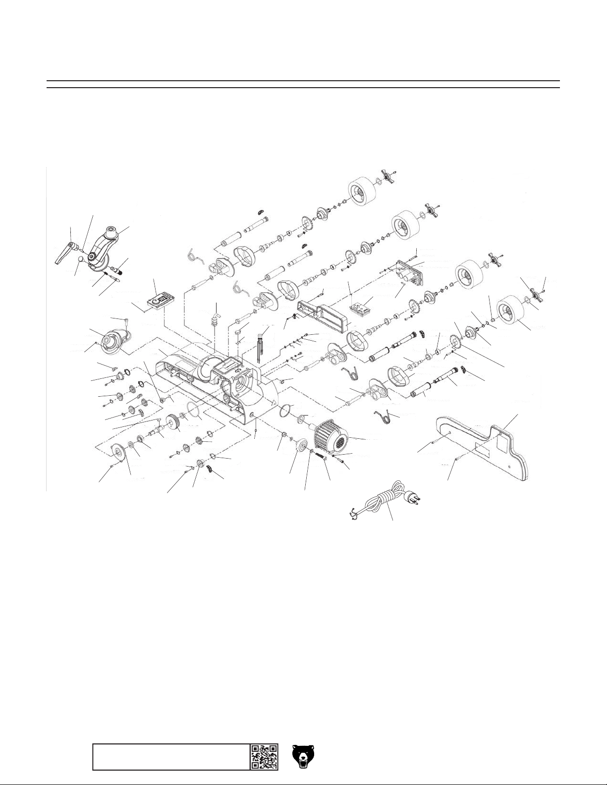
56
88
We do our best to stock replacement parts when possible, but we cannot guarantee that all parts shown
are available for purchase. Call (800) 523-4777 or visit www.grizzly.com/parts to check for availability.
60
53
59
51
44
57
47
45
58
39
43
52
38
48
46
55
74
42
54
SECTION 9: PARTS
Main
50
41
73
26
40
37
19
49
18
36
27
44
35
68
45
47
16
34
33
28
80
66
67
83
84
69
70
71
32
29
31
65
82
79
78
64
81
3
4
85
86
87
30
77
1
76
75
5
21
14
12
11
10
9
2
7
6
63
25
17
15
62
13
8
24
23
20
22
72
61
-32-
BUY PARTS ON LINE AT GRIZ ZLY.COM !
Scan QR code to visit our Parts Store.
Model T33926 (Mfd. Since 08/23)

Main Parts List
REF PART # DES CRIP TIO N REF PART # DES CRIP TIO N
1 PT33926001 SPROCKET CASE 45 PT33926045 DOUBLE-SPROCKET 12T X 3/8"
2 PT33926002 SPROCKET SHAFT 46 PT33926046 CHAIN 36S
3 PT33926003 LOCK WASHER 12MM 47 PT33926047 CHAIN 20S
4 PT33926004 HEX BOLT M12-1.75 X 75 48 PT33926048 CHAIN 14S
5 PT33926005 GREASE FITTING M6-1 STRAIGHT 49 PT33926049 O RING 11.8 X 2.4 P12
6 PT33926006 CASE COVER 50 PT33926050 OIL FILL PLUG
7 PT33926007 TORSION SPRING 51 PT33926051 LOWER ELBOW PIVOT JOINT
8 PT33926008 ROLLER SUPPORT 52 PT33926052 CAP SCREW M8-1.25 X 25
9 PT33926009 BUSHING 53 PT33926053 LOCK PIN
10 PT33926010 SPACER 54 PT33926054 LOWER ELBOW JOINT
11 PT33926011 SPACER 55 PT33926055 STANDOFF HEX M16-1.5 X 82
12 PT33926012 KEYED WASHER 12 X 16 X 1 56 PT33926056 ADJUSTABLE HANDLE M6-1, 108L
13 PT33926013 FLAT WASHER 12 X 16 X 1 57 PT33926057 PIN 1 X 15 X 16
14 PT33926014 RECESSED HEX NUT M10-1.5 58 PT33926058 LOCATING PIN
15 PT33926015 SPROCKET SHAFT TUBE 59 PT33926059 COMPRESSION SPRING 0.8 X 8 X 23
16 PT33926016 EXT RETAINING RING 26MM 60 PT33926060 PIVOT LOCK KNOB M6-1, 22D
17 PT33926017 SPROCKET SHAFT 61 PT33926061 CHAIN COVER
18 PT33926018 EXT RETAINING RING 15MM 62 PT33926062 CAP SCREW M6-1 X 20
19 PT33926019 GREASE FITTING M6-1 STRAIGHT 63 PT33926063 CAP SCREW M6-1 X 30
20 PT33926020 CHAIN 26S 64 PT33926064 CIRCUIT BOARD COVER
21 PT33926021 WING NUT M16-2 65 PT33926065 CAP SCREW M5-.8 X 25
22 PT33926022 WAVY WASHER 16MM 66 PT33926066 WIRE CLAMP (PLASTIC)
23 PT33926023 SPROCKET 22T X 3/8" 67 PT33926067 PHLP HD SCR M4-.7 X 8
24 PT33926024 LOCK WASHER 6MM 68 PT33926068 STRAIN RELIEF TYPE-3 PG11
25 PT33926025 CAP SCREW M6-1 X 20 69 PT33926069 SPACER
26 PT33926026 POWER FEEDER BODY 70 PT33926070 O-RING 59.4 X 3.1 G60
27 PT33926027 BUSHING 71 PT33926071 OIL SEAL
28 PT33926028 SET SCREW M6-1 X 10 72 PT33926072 ROLLER 4-3/4 X 2-3/8
29 PT33926029 KNOB 65D X 38L X 10B 73 PT33926073 CONTROL PANEL
30 PT33926030 CAP SCREW M10-1.5 X 50 74 PT33926074 TAP SCREW M4 X 12
31 PT33926031 FLAT WASHER 10MM 75 PT33926075 CIRCUIT BOARD J011238-1
32 PT33926032 FLANGE NUT M10-1.5 76 PT33926076 CAP SCREW M5-.8 X 40
33 PT33926033 OIL SIGHT GLASS 77 PT33926077 FUSE 8A 250V GLASS
34 PT33926034 OIL SIGHT GLASS PANEL 78 PT33926078 CIRCUIT BOARD BT-220-RT-V1
35 PT33926035 O-RING 71.4 X 3.1 G72 79 PT33926079 PHLP HD SCR M4-.7 X 8
36 PT33926036 GEAR 30T 80 PT33926080 ON/OFF SWITCH FINGLAI R16-503AD
37 PT33926037 GEAR SHAFT 81 PT33926081 CAP SCREW M5-.8 X 12
38 PT33926038 KEY 6 X 6 X 18 82 PT33926082 FLAT WASHER 5MM
39 PT33926039 EXT RETAINING RING 15MM 83 PT33926083 EXT TOOTH WASHER 5MM
40 PT33926040 BALL BEARING 6003ZZ 84 PT33926084 GROUND WIRE 18G 4-3/4"
41 PT33926041 OIL SEAL 17 X 32 X 7MM 85 PT33926085 MOTOR 500W 220V 1-PH DC
42 PT33926042 GEAR COVER 86 PT33926086 LOCK WASHER 6MM
43 PT33926043 CAP SCREW M6-1 X 16 87 PT33926087 CAP SCREW M6-1 X 20
44 PT33926044 SPROCKET 3/8" 12T 88 PT33926088 POWER CORD 18G 3W 108" 6-15P
Model T33926 (Mfd. Since 08/23)
BUY PARTS ON LINE AT GRIZ ZLY.COM !
Scan QR code to visit our Parts Store.
-33-
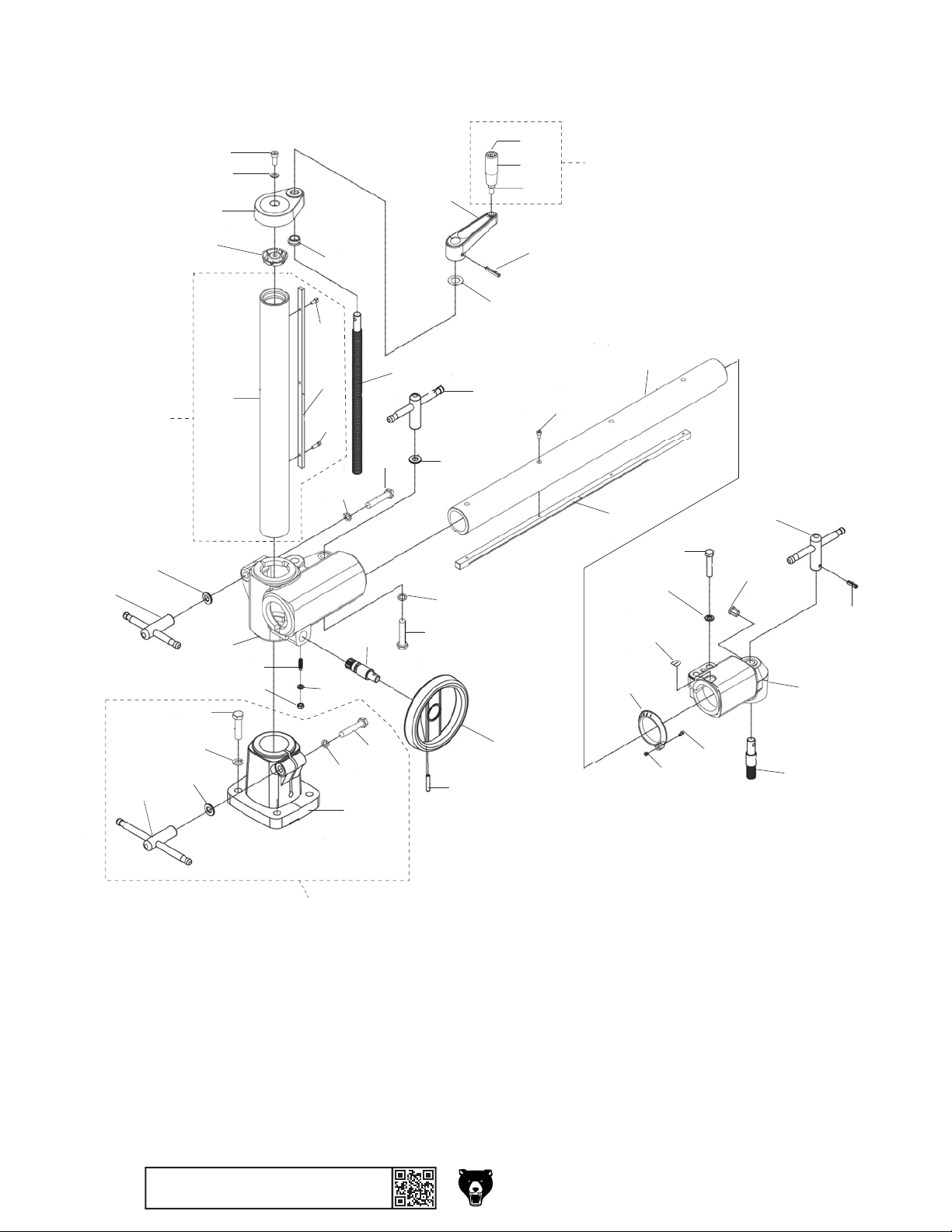
Column & Stand
118
109
117
123
120
107
122
121
110
114
135
137
112
111
113
136
124
116
134
115
119
126
115
117
116
118
125
130
129
131
127
140
128
139
141
138
150
147
145
146
151
148
144
-34-
108
105
106
101
BUY PARTS ON LINE AT GRIZ ZLY.COM !
Scan QR code to visit our Parts Store.
104
102
103
132
133
142
143
149
Model T33926 (Mfd. Since 08/23)

Column & Stand Parts List
REF PART # DES CRIP TIO N REF PART # DES CRIP TIO N
101 PT33926101 VERTICAL COLUMN BASE ASSY 127 PT33926127 ROLL PIN 6 X 36
102 PT33926102 VERTICAL COLUMN BASE 128 PT33926128 VERTICAL TRAVEL CRANK HANDLE ASSEMBLY
103 PT33926103 HEX BOLT M12-1.75 X 75 129 PT33926129 HOLLOW HANDLE 25 X 69, 10
104 PT33926104 LOCK WASHER 12MM 130 PT33926130 CAP SCREW M10-1.5 X 85
105 PT33926105 FLAT WASHER 12MM 131 PT33926131 HEX NUT M10-1.5
106 PT33926106 SLIDING T-HANDLE M12-1.75, 200MM 132 PT33926132 ROLL PIN 6 X 36
107 PT33926107 HEX BOLT M12-1.75 X 50 133 PT33926133 HANDWHEEL TYPE-17 160D X 17MM
108 PT33926108 LOCK WASHER 12MM 134 PT33926134 PINION
109 PT33926109 VERTICAL COLUMN ASSEMBLY 135 PT33926135 SET SCREW M8-1.25 X 25 DOG-PT
110 PT33926110 VERTICAL COLUMN 136 PT33926136 LOCK WASHER 8MM
111 PT33926111 VERTICAL COLUMN RACK 137 PT33926137 HEX NUT M8-1.25
112 PT33926112 CAP SCREW M5-.8 X 10 138 PT33926138 OVER ARM SHAFT 720MM
113 PT33926113 CAP SCREW M5-.8 X 16 139 PT33926139 OVER ARM SHAFT RACK 650MM
114 PT33926114 ELEVATING BRACKET 140 PT33926140 CAP SCREW M5-.8 X 10
115 PT33926115 HEX BOLT M12-1.75 X 75 141 PT33926141 ANGLE DIAL SCALE
116 PT33926116 LOCK WASHER 12MM 142 PT33926142 PHLP HD SCR M4-.7 X 15
117 PT33926117 FLAT WASHER 12MM 143 PT33926143 HEX NUT M4-.7
118 PT33926118 SLIDING T-HANDLE M12-1.75, 150MM 144 PT33926144 UPPER ELBOW-JOINT
119 PT33926119 ELEVATION LEADSCREW 145 PT33926145 STRAIN RELIEF TYPE-1 6MM
120 PT33926120 FINNED ANCHOR M8-1.25 146 PT33926146 LOCK WASHER 10MM
121 PT33926121 FLAT WASHER 8MM 147 PT33926147 HEX BOLT M10-1.5 X 50
122 PT33926122 CAP SCREW M8-1.25 X 25 148 PT33926148 POINTER PANEL
123 PT33926123 COLUMN CAP 149 PT33926149 STANDOFF STUD M16-2
124 PT33926124 LEADSCREW BUSHING 150 PT33926150 T-HANDLE, M6-1, 150MM W/HOLE FOR PIN
125 PT33926125 FLAT WASHER 17 X 30 X 0.5MM 151 PT33926151 ROLL PIN 6 X 22
126 PT33926126 VERTICAL TRAVEL CRANK 130L
Model T33926 (Mfd. Since 08/23)
BUY PARTS ON LINE AT GRIZ ZLY.COM !
Scan QR code to visit our Parts Store.
-35-
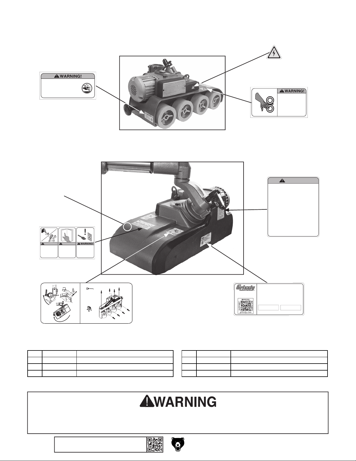
206
• Do not expose to rain or use in
damp locations.
• AVERTISSEMENT!: Ne pas
exposer à la pluie et ne pas
utiliser dans les emplacements
humides.
208
HAZARD!
WARNING!
To reduce risk of death
or serious injury, read
manual BEFORE using
machine.
To get a new manual,
call (800) 523-4777 or
go to www.grizzly.com.
WARNING!
ENTANGLEMENT
Tie back long hair, roll up
long sleeves, and remove
loose clothing, jewelry, or
gloves to prevent getting
caught in moving parts.
207
201
DISCONNECT
POWER BEFORE
ADJUSTMENTS,
MAINTENANCE, OR
SERVICE.
Labels & Cosmetics
202
CRUSHING
INJURY HAZARD!
Do not place hands
between top and
bottom rollers.
Crushing injuries may
occur.
203
WARNING
To reduce risk of serious injury when using:
1. Read and understand owner’s manual before
operating.
2. Always wear eye protection.
3. Only plug power cord into a grounded outlet.
4. Keep hands away from rotating wheels or other
moving parts that could cause entanglement.
5. Keep guards in place at all times.
6. Do not wear loose clothing, gloves, jewelry, or
other items that can get entangled. Tie back
long hair and roll up sleeves.
7. Disconnect power before servicing, adjusting.
8. Do not operate under influence of drugs,
alcohol, or when tired.
9. Properly install and adjust machine before
starting.
10. Adjust wheel height for each workpiece
thickness to reduce risk of kickback.
11. Do not use with workpieces shorter than
specified minimum length.
204
2
1
2
Gear Oil
2
2
2
2
2
MODEL T33926
EASY FEEDER
1
B
Every 1000
Hours 80-90W
A
2
Every 200
C
Hours NLGI
2 Grease
Specifications
Power Requirement: 220V, 1-Ph, 15A, 60 Hz
Motor: 500 Watt (2/3 HP), 220V, 1-Ph, 60 Hz, 2.3A
Feed Speed: 5–72 FPM (Variable)
Roller Width: 2-3/8'' / Roller Suspension: 3/4''
Minimum Workpiece Length: 6''
Movement: 9-3/4'' (Vertical), 17-1/3'' (Horizontal)
Weight: 115 lbs.
Date
Mfd. for Grizzly in Taiwan
S/N
205
REF PART # DE SCRI PTION REF PART # DE SCRI PTION
201 PT33926201 WATER EXPOSURE WARNING LABEL 205 PT33926205 MACHINE ID LABEL
202 PT33926202 ELECTRICITY LABEL 206 PT33926206 LUBRICATION NOTICE
203 PT33926203 CRUSHING HAZARD WARNING LABEL 207 PT33926207 COMBO WARNING LABEL
204 PT33926204 OPERATION WARNING LABEL 208 PT33926208
TOUCH-UP PAINT, GRIZZLY GREEN
Safety labels help reduce the risk of serious injury caused by machine hazards. If any label comes
off or becomes unreadable, the owner of this machine MUST replace it in the original location
before resuming operations. For replacements, contact (800) 523-4777 or www.grizzly.com.
-36-
BUY PARTS ON LINE AT GRIZ ZLY.COM !
Scan QR code to visit our Parts Store.
Model T33926 (Mfd. Since 08/23)

WARRANTY & RETURNS
Grizzly Industrial, Inc. warrants every product it sells for a period of 1 year to the original purchaser from
the date of purchase. This warranty does not apply to defects due directly or indirectly to misuse, abuse,
negligence, accidents, repairs or alterations or lack of maintenance. This is Grizzly’s sole written warranty
and any and all warranties that may be implied by law, including any merchantability or fitness, for any particular purpose, are hereby limited to the duration of this written warranty. We do not warrant or represent
that the merchandise complies with the provisions of any law or acts unless the manufacturer so warrants.
In no event shall Grizzly’s liability under this warranty exceed the purchase price paid for the product and
any legal actions brought against Grizzly shall be tried in the State of Washington, County of Whatcom.
We shall in no event be liable for death, injuries to persons or property or for incidental, contingent, special,
or consequential damages arising from the use of our products.
The manufacturers reserve the right to change specifications at any time because they constantly strive to
achieve better quality equipment. We make every effort to ensure that our products meet high quality and
durability standards and we hope you never need to use this warranty.
In the event you need to use this warranty, contact us by mail or phone and give us all the details. We will
then issue you a “Return Number,’’ which must be clearly posted on the outside as well as the inside of
the carton. We will not accept any item back without this number. Proof of purchase must accompany the
merchandise.
Please feel free to write or call us if you have any questions about the machine or the manual.
Thank you again for your business and continued support. We hope to serve you again soon.
To
you can
applicable information for
take advantage of this warranty, you must register it at https://www.grizzly.com/forms/warranty, or
scan the QR code below to be automatically directed to our warranty registration page. Enter all
the product.
WARRANTY

 Loading...