

Page 1
MODEL T33448
THIN KERF RIVING KNIFE
FOR G1023RL SERIES
INSTRUCTIONS
For questions or help with this product contact Tech Support at (570) 546-9663 or techsupport@grizzly.com
Introduction
Install the Model T33448 on your G1023RL series
table saw for use with a thin kerf blade that matches the below specifications. The Model T33448 is
compatible with the existing table insert and will
reduce the risk of your workpiece pinching and
binding while performing non-through cuts that
require the removal of the blade guard.
• Riving knife MUST BE aligned with blade
and secured tightly. A misaligned riving
knife can cause workpiece to catch or
bind, increasing the risk of kickback.
• Use a riving knife for all non-through
operations, unless dado blade with less
than 10 in. diameter is installed.
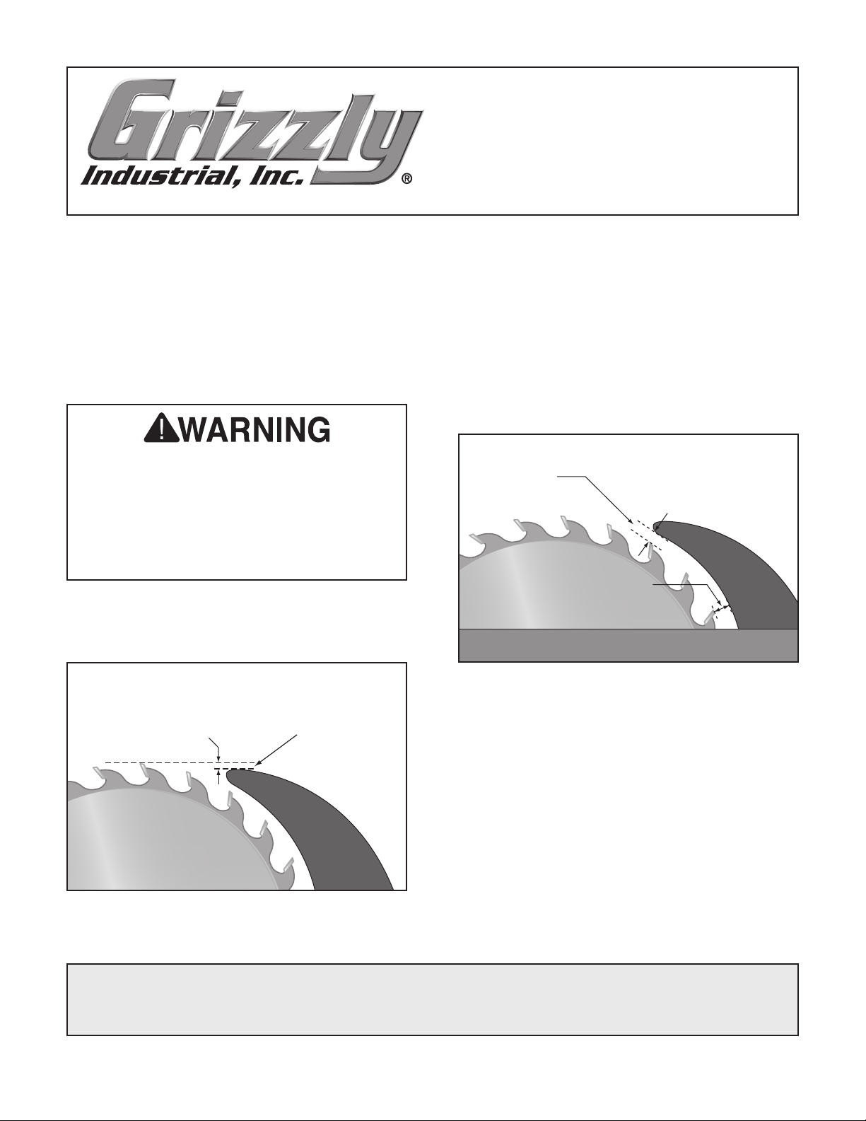
A riving knife mounts just below the blade's highest point of rotation, as shown in Figure 1.
The height difference between the riving knife and
the blade allows the workpiece to pass over the
blade during non-through cuts (those in which the
blade does not cut all the way through the thickness of the workpiece.
The riving knife must also be kept within the range
shown in Figure 2. For these reasons, this riving
knife is only compatible with 10" blades, as listed
below in the Specifications.
Top Distance
Minimum 3mm
Maximum 8mm
Bottom Distance
Minimum 3mm
Maximum 8mm
Minimum 1mm
Maximum 5mm
Figure 1. Height difference between riving knife
and blade.
OR FORM WITHOUT THE WRITTEN APPROVAL OF GRIZZLY INDUSTRIAL, INC.
Height Difference
COPYRIGHT © FEBRUARY, 2023 BY GRIZZLY INDUSTRIAL, INC.
NO PORTION OF THIS MANUAL MAY BE REPRODUCED IN ANY SHAPE
(FOR MODELS MFD. SINCE 03/23) #CS22565 PRINTED IN TAIWAN
***Keep for Future Reference***
Figure 2. Allowable top and bottom distances
between riving knife and blade.
Specifications
• Riving Knife Thickness ......................... 2mm
• Required Blade Diameter .....................10 in.
• Required Blade Body Thickness ....... 1.8mm
• Required Blade Kerf Thickness......... 2.2mm
V1.02.23
Page 2

Installation
Items Needed Qty
Open or Closed-End Wrench 1⁄2 " ...................... 1
Straightedge 12"
Hex Wrenches 4, 5mm
To install thin kerf riving knife:
................................................ 1
................................1 Ea.
To reduce risk of shock or
accidental startup, always
disconnect machine from
power before adjustments,
maintenance, or service.
4. Fully tighten lock nut on lever assembly while
lever is in locked position (see Figure 4). Pull
riving knife up to verify it is locked.
Lock Nut
1. Install thin kerf blade (refer to Steps 1–4
of Blade Installation section of Owner's
Manual) meeting specification requirements
on Page 1 of this update, and tilt blade to 90°.
Open right access door.
2.
3. Flip quick-release lever up, insert riving knife
into spreader adjustment bracket, then push
lever down (see Figure 3).
Quick-Release
Lever
Spreader
Adjustment
Bracket
Figure 4. Location of lever assembly lock nut.
5. Check 90° stop bolt adjustment in Blade Tilt
Stops section of Owner's Manual.
Place straightedge against top and bottom of
6.
blade and riving knife, as shown in Figure 5.
Top Alignment
Bottom Alignment
Figure 5. Checking top and bottom riving knife
parallelism with blade.
Figure 3. Location of quick-release lever (viewed
from inside cabinet).
-2-
Model T33448 (Mfd. Since 03/23)
Page 3
Riving knife should be parallel with blade
along its length at both positions and should
be in "Alignment Zone," as shown in Figure 6.
Alignment
Zone
Riving
Knife
Blade
Straightedge
Figure 6. Riving knife alignment zone.
Flip quick-release lever up to remove riving
8.
knife.
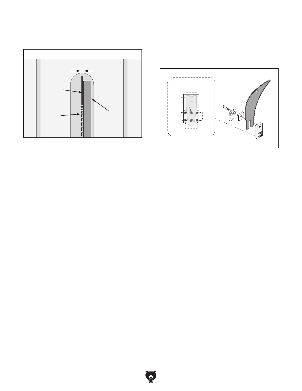
Loosen (2) cap screws on mounting block,
9.
then adjust set screws on block to move it in
necessary direction (see Figure 7).
Mounting Block
Top Control
Cap
Screw
Control
Side
Side
Control
Bottom Control
— If riving knife is not parallel with blade
at either top or bottom, it may be bent.
Remove riving knife and place it on a flat
surface and check to see if riving knife
lays evenly along its length. If riving knife
does not lay evenly, proceed to Step 7.
— If riving knife is not parallel with blade or
is not inside alignment zone, proceed to
Step 8.
— If riving knife is parallel with blade and
inside alignment zone, close right access
door and install table insert. No additional
steps are necessary.
Bend riving knife by hand while installed or
7.
remove it to straighten it. Repeat Step 6 to
determine if riving knife is parallel with blade.
— I f riving knife cannot be straightened prop-
erly, replace it.
Figure 7. Mounting block controls.
10. Install riving knife, then repeat Step 6.
— If riving knife is in alignment zone, proceed
to Step 11.
— If riving knife is not in alignment zone,
continue adjusting set screws on mounting
block as necessary to correctly position
riving knife.
Remove riving knife, tighten (2) cap screws
11.
on mounting block to secure riving knife
adjustment, then install riving knife.
Close right access door and install table
12.
insert.
Model T33448 (Mfd. Since 03/23)
-3-
Page 4

 Loading...