

Page 1
MODEL T32716
To reduce your risk of
serious injury, read this
entire manual BEFORE
8" BENCHTOP
METAL SHEAR/BRAKE
INSTRUCTIONS
For questions or help with this product contact Tech Support at (570) 546-9663 or techsupport@grizzly.com
Introduction
The Model T32716 8" Benchtop Metal Shear/
Brake is designed to both bend and shear sheet
metal with one compact tool.
using machine.
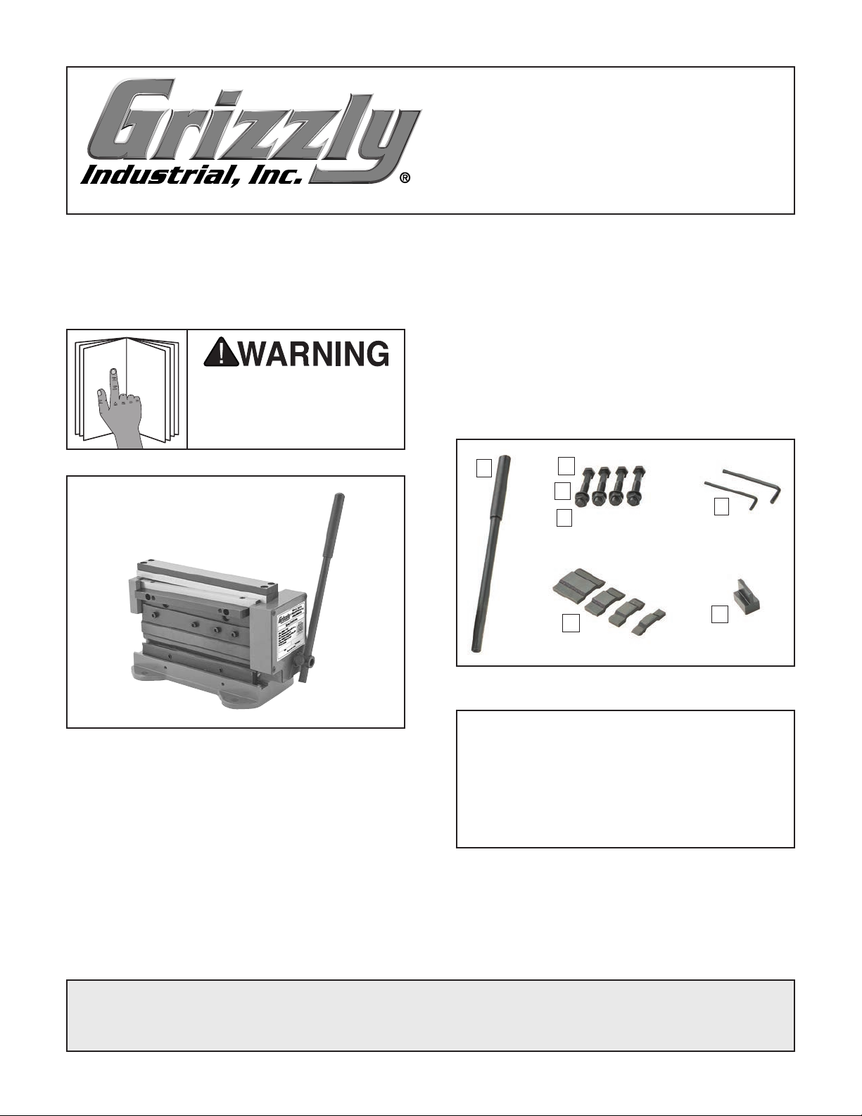
Inventory
Description Qty
A. Benchtop Shear/Brake (Not Shown) .......... 1
Handle ........................................................ 1
B.
Hex Bolts M10-2 x 70 ................................. 4
C.
Flat Washers 10mm ................................... 4
D.
Hex Nuts M10-2 .......................................... 4
E.
Hex Wrenches 3, 4mm .........................1 Ea.
F.
Fingers
G.
Seating Tool................................................ 1
H.
B
3
⁄8", 9⁄16", 13⁄16", 19⁄16" ..................1 Ea.
C
D
E
G
F
H
Figure 1. Model T32716 8" Benchtop Metal
Shear/Brake.
Needed for Setup
• Safety Glasses ....................................1 Pair
• Cleaner/Degreaser ..................... As Needed
• Disposable Shop Rags ............... As Needed
• Disposable Gloves ..................... As Needed
• Open-End Wrench 17mm ........................... 1
• Wrench or Socket 17mm ............................ 1
COPYRIGHT © MAY, 2021 BY GRIZZLY INDUSTRIAL, INC.
NO PORTION OF THIS MANUAL MAY BE REPRODUCED IN ANY SHAPE
OR FORM WITHOUT THE WRITTEN APPROVAL OF GRIZZLY INDUSTRIAL, INC.
(FOR MODELS MFD. SINCE 05/21) #CS21863 PRINTED IN CHINA
Figure 2. Inventory.
NOTICE
If you cannot find an item on this list, carefully check around/inside the machine and
packaging materials. Often, these items get
lost in packaging materials while unpacking or they are pre-installed at the factory.
V1.05.21
Page 2

MACHINE DATA
SHEET
Customer Service #: (570) 546-9663 · To Order Call: (800) 523-4777 · Fax #: (800) 438-5901
MODEL T32716 8" BENCHTOP METAL SHEAR/BRAKE
Product Dimensions:
Weight................................................................................................................................................................ 26 lbs.
Width (side-to-side) x Depth (front-to-back) x Height........................................................................... 11 x 16 x 12 in.
Footprint (Length x Width)......................................................................................................................... 9-1/2 x 6 in.
Shipping Dimensions:
Type..................................................................................................................................................... Cardboard Box
Content........................................................................................................................................................... Machine
Weight................................................................................................................................................................ 29 lbs.
Length x Width x Height......................................................................................................................... 19 x 13 x 7 in.
Main Specifications:
Capacities
Maximum Width..................................................................................................................................... 7-7/8 in.
Maximum Thickness at Half Width Mild Steel..................................................................................... 20 Gauge
Maximum Thickness at Full Width Mild Steel..................................................................................... 22 Gauge
Aluminum............................................................................................................................................ 18 Gauge
Soft Brass........................................................................................................................................... 18 Gauge
Hard Copper....................................................................................................................................... 20 Gauge
Minimum Reverse Bend........................................................................................................................... 1/4 in.
Maximum Height of Pan/Box Brake Sides................................................................................................ 5/8 in.
Number of Fingers............................................................................................................................................ 5
Width of Fingers................................................................................................... 3/8, 9/16, 13/16, 1-9/16, 8 in.
Construction
Base..................................................................................................................................................... Cast Iron
Brake.................................................................................................................. Ground Steel, Hardened Edge
Fingers............................................................................................................... Ground Steel, Hardened Edge
Frame................................................................................................................................................... Cast Iron
Shear Blades................................................................................................ Precision-Ground Hardened Steel
Other Specifications:
Country of Origin ................................................................................................................................................ China
Warranty ........................................................................................................................................................... 1 Year
Approximate Assembly & Setup Time ........................................................................................................ 15 Minutes
Serial Number Location ................................................................................................................... Machine ID Label
Features:
Adjustable Brake & Shear Stops
Reversible Bending Prism w/2 V-Groove Sizes: 6 & 11mm Wide
Accessories Included:
Hex Wrenches 3, 4mm
Finger Seating Tool
-2-
T32716 (Mfd. Since 05/21)
Page 3

Another option is a "direct mount" (see example
below) where the machine is secured directly to
the workbench with lag screws and washers.
The base of this machine has mounting holes
Cleanup
The unpainted surfaces of your machine are
coated with a heavy-duty rust preventative that
prevents corrosion during shipment and storage.
This rust preventative works extremely well, but it
will take a little time to clean.
Workbench Mounting
Mounting hardware has been included with the
Model T32716. However, you can use different
hardware with a 10mm diameter if your workbench
or surface requires a different size or type.
Be patient and do a thorough job cleaning your
machine. The time you spend doing this now will
give you a better appreciation for the proper care
of your machine's unpainted surfaces.
There are many ways to remove this rust preventative, but the following steps work well in a wide
variety of situations. Always follow the manufacturer’s instructions with any cleaning product you
use and make sure you work in a well-ventilated
area to minimize exposure to toxic fumes.
Before cleaning, gather the following:
• Disposable rags
• Cleaner/degreaser (WD•40 works well)
• Safety glasses & disposable gloves
• Plastic paint scraper (optional)
Basic steps for removing rust preventative:
Put on safety glasses.
1.
2. Coat the rust preventative with a liberal
amount of cleaner/degreaser, then let it soak
for 5–10 minutes.
Wipe off the surfaces. If your cleaner/
3.
degreaser is effective, the rust preventative
will wipe off easily. If you have a plastic paint
scraper, scrape off as much as you can first,
then wipe off the rest with the rag.
that allow it to be fastened to a workbench or
other mounting surface to prevent it from moving
during operation and causing accidental injury or
damage.
The strongest mounting option is a "Through
Mount" (see example below) where holes are
drilled all the way through the workbench—and
hex bolts, washers, and hex nuts are used to
secure the machine in place.
Hex
Bolt
Flat Washer
Machine Base
Workbench
Flat Washer
Lock Washer
Hex Nut
Figure 3. "Through Mount" setup.
Repeat Steps 2–3 as necessary until clean,
4.
then coat all unpainted surfaces with a quality
metal protectant to prevent rust.
NOTICE
Avoid harsh solvents like acetone or brake
parts cleaner that may damage painted surfaces. Always test on a small, inconspicuous location first.
T32716 (Mfd. Since 05/21)
Lag Screw
Flat Washer
Machine Base
Workbench
Figure 4. "Direct Mount" setup.
-3-
Page 4

Assembly
Crushing hazard! Always
keep hands clear when
The machine must be fully assembled before it
can be operated. Before beginning the assembly
process, first clean any parts that are covered or
coated in rust preventative.
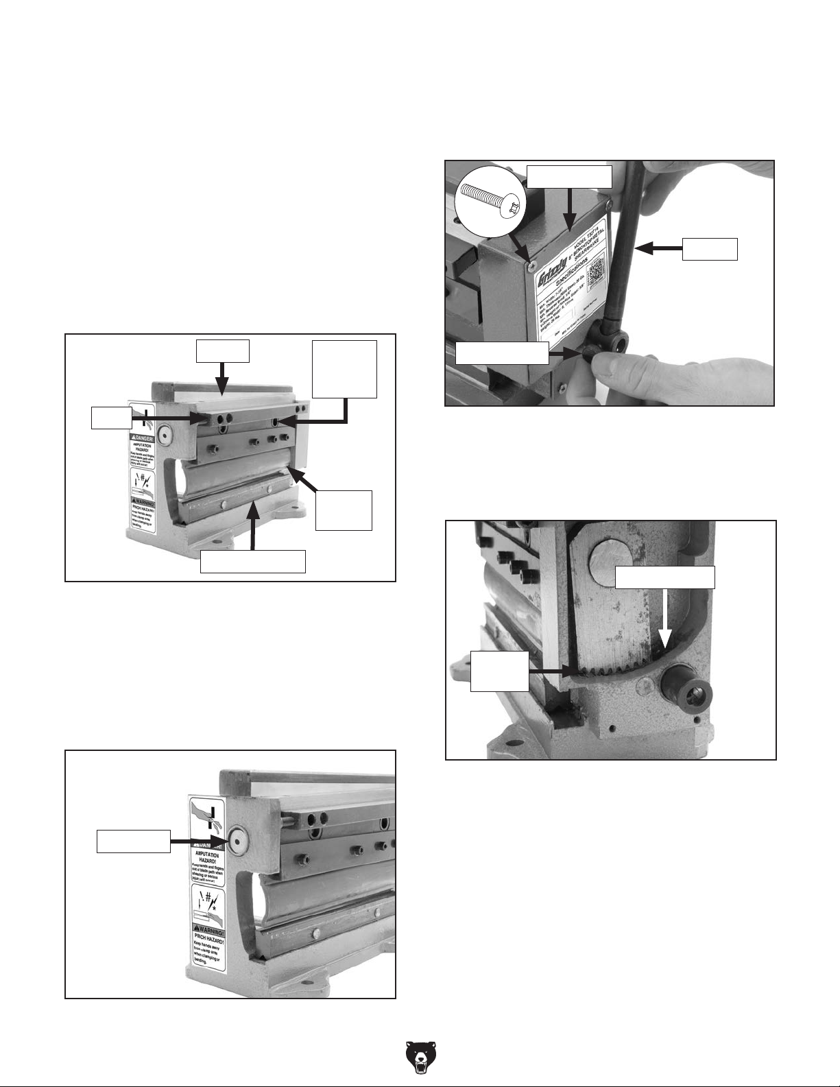
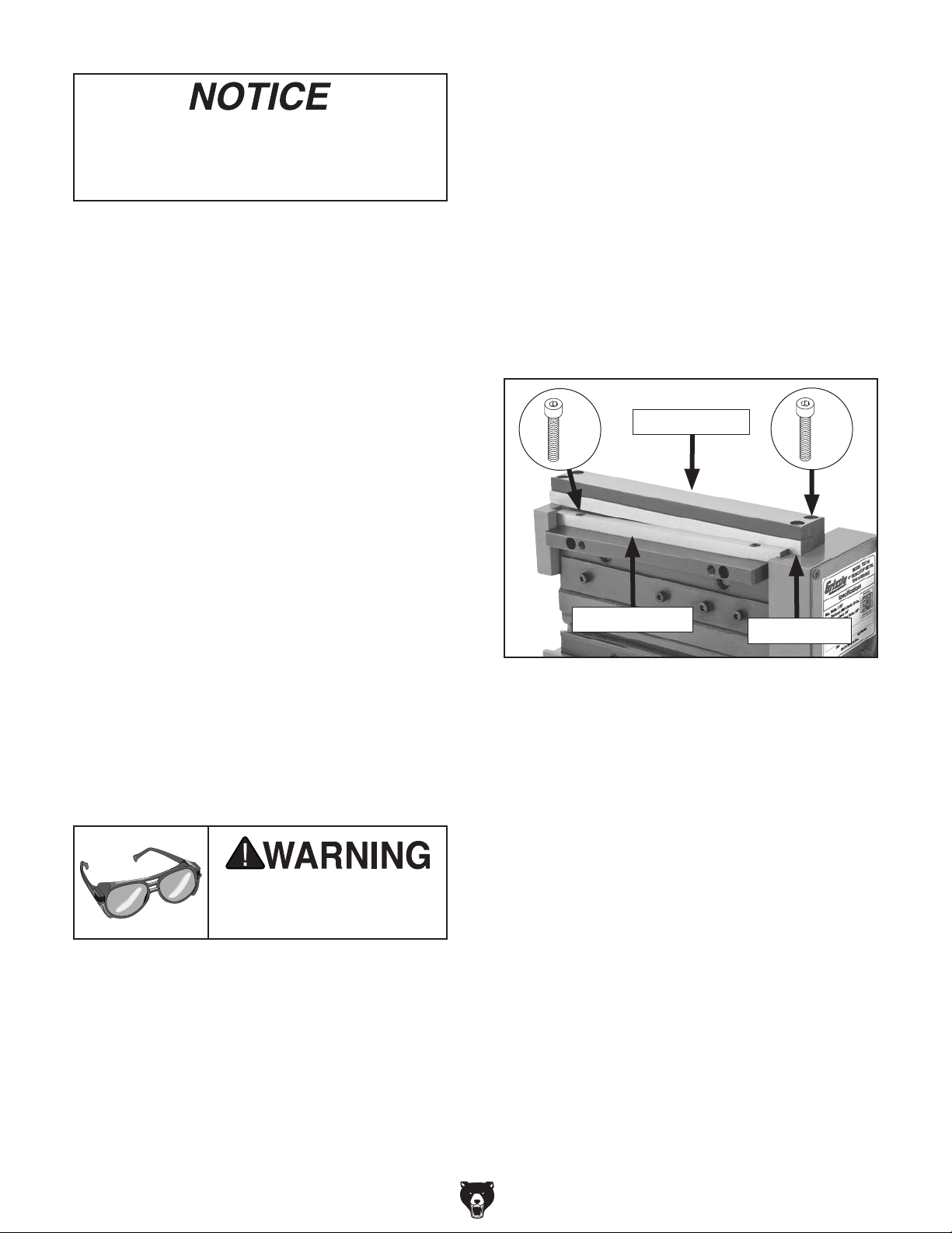
Remove unneeded fingers by sliding them
3.
left and out of gib (see Figure 6).
To assemble machine:
Insert handle into hub so tip of thumb knob
1.
fits in groove in handle and secure in place
with thumb knob (see Figure 5).
Handle
Groove
Hub
Thumb Knob
Figure 5. Installing handle.
Changing Fingers
The Model T32716 comes with five fingers of
various lengths:
sizes can be used to perform a variety of bending operations, including pan and box and radius
bending. Once you have planned your bend,
remove any installed fingers and replace them
with the finger (or fingers) needed for that bend.
3
⁄8", 9⁄16", 13⁄16", 19⁄16", and 8". These
x 4
Gib
Finger
Figure 6. Finger mounting components.
4.
Slide desired finger (or fingers) between gib
and bending prism in order necessary for
bending operation (see Figure 7).
using this machine.
5. Use handle to lower and press fingers against
bending prism to align them (see Figure 7).
Tool Needed Qty
Hex Wrench 4mm .............................................. 1
To change fingers:
Loosen (4) gib cap screws shown in Figure 6.
1.
Use handle to lift any installed fingers as high
2.
as possible (see Figure 6).
-4-
Fingers
Bending
Prism
Figure 7. Finger installation components.
6.
With finger (or fingers) still pressed against
bending prism, tighten cap screws from
Step 1.
T32716 (Mfd. Since 05/21)
Page 5

Flipping Bending Prism
The bending prism is what the fingers press a
workpiece up against to achieve a bend. This
prism can be turned over to reveal a shallower
V-groove with a smaller bending radius on the
other side.
To flip bending prism:
Typical Bending Operation
Use the following steps to perform a typical bend
on a workpiece. If needed, the brake stop can be
adjusted so more than one bend can be made at
the same location. For pan or box bending, refer
to Pan & Box Bending on Page 7. For bending
a cylinder or cone, refer to Radius Bending on
Page 8.
Loosen brake stop thumb screws and slide
1.
stop off its support rods if installed (see
Figure 8).
Thumb Screw
(1 of 2)
Brake Stop
Figure 8. Location of brake stop components.
2.
Use handle to lift fingers out of bending
prism, then remove prism from prism seat
(see Figure 9).
Support Rod
(1 of 2)
Tip: During a bending operation, workpiece scor-
ing may occur. To avoid these marks, keep the
bending prism free of burrs, and adhere a strip of
tape on the workpiece over the area that will be
bent.
Eye injury hazard! Always
wear safety glasses when
using bending function of
machine.
Do not operate unless machine has been
securely clamped or mounted to workbench.
Failure to secure machine before use could
result in crushing injuries.
Bending
Prism
Prism
Seat
Figure 9. Location of bending prism and seat.
3.
Turn bending prism over to reveal opposite
side and V-groove, then place prism in prism
seat.
Install brake stop removed in Step 1 for
4.
performing repeated bends (see Typical
Bending Operation for more information).
T32716 (Mfd. Since 05/21)
Only bend stock that falls within bending
capacity of this machine. Stock thicker than
20 gauge will damage machine when bent.
Items Needed Qty
Masking Tape .................................... As Needed
Marker/Pencil
Protractor
To perform bending operation:
Tape and mark workpiece with location of
1.
desired bend.
Install fingers and prepare bending prism for
2.
desired operation (see Changing Fingers on
Page 4 and Flipping Bending Prism).
Use handle to raise fingers.
3.
..................................................... 1
........................................................... 1
-5-
Page 6

Crushing hazard! Always
keep hands clear when
5.
While holding workpiece steady, use handle
to lower fingers and bend workpiece to
desired bend radius (see Figure 13).
using this machine.
4.
Rest workpiece on bending prism and use
handle to lower fingers enough to align mark
from Step 1 with finger tips (see Figure 11).
Desired Bend
Position
Workpiece
Figure 111. Example of aligning workpiece with
finger tips.
— If brake stop keeps workpiece from resting
flat on bending prism, loosen brake stop
thumb screws and remove brake stop (see
Figure 12).
Tip: Use protractor to measure bend angle.
Figure 13. Example of bent workpiece.
Raise fingers and remove workpiece.
6.
7. If reverse bend is required, repeat Steps 1–6
but with workpiece upside-down.
Note: Minimum reverse bend possible is 1⁄4"
(see Figure 14).
— If performing repeated bends, loosen brake
stop thumb screws and adjust brake stop
to edge of workpiece (see Figure 12).
Thumb Screw
(1 of 2)
Brake Stop
Figure 12. Location of brake stop and thumb
screws.
-6-
Figure 14. Example of reverse bend.
T32716 (Mfd. Since 05/21)
Page 7

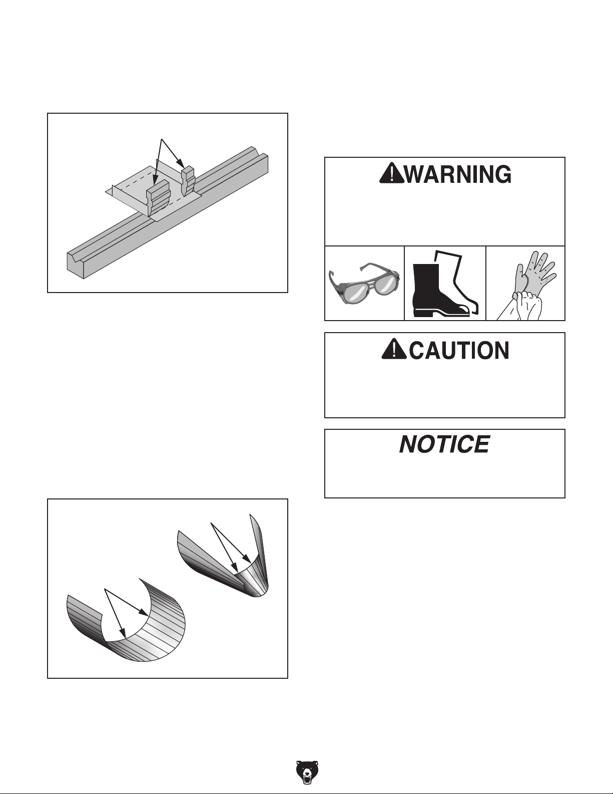
Pan & Box Bending
When bending a piece of flat metal into a box, you
should be able to make the first two bends with
whichever fingers you like (see Figure 15).
Figure 15. Example of straight bending.
Use this information as well as the following steps
to bend a pan or box. Install the brake stop so the
pan height will be the same on all four sides.
Eye injury hazard! Always
wear safety glasses when
using bending function of
machine.
However, for the remaining bends, there needs to
be clearance for those first bends (see Figure 16).
8" Finger
!
Bending Prism
Figure 16. Insufficient clearance for first bends.
To provide the necessary clearance for the previous bends, the smaller fingers can be installed
like shown in Figure 17.
Do not operate unless machine has been
securely clamped or mounted to workbench.
Failure to secure machine before use could
result in crushing injuries.
Only bend stock that falls within bending
capacity of this machine. Stock thicker than
20 gauge will damage machine when bent.
Items Needed Qty
Masking Tape .................................... As Needed
Marker/Pencil
Protractor or Machinist's Square
To perform pan & box bending:
Follow Steps 1–6 of Typical Bending
1.
Operation beginning on Page 5 to perform
first two bends (see Figure 15).
Tape and mark workpiece with location of
2.
third bend.
..................................................... 1
....................... 1
Smaller Fingers
Bending Prism
Figure 17. Sufficient clearance for first bends.
T32716 (Mfd. Since 05/21)
Install fingers for third bend (see Changing
3.
Fingers on Page 4).
-7-
Page 8
Note: Fingers do not need to equal length of
bend. They can be placed with a small distance between them as long as outside length
equals workpiece bend (see Figure 18).
Fingers
Figure 18. Proper finger placement.
4.
Bend remaining sides.
Shearing Operation
In addition to bending metal, this machine also
consists of a set of reversible knives that shear up
to 20-gauge full width mild steel. A movable lower
knife passes next to the fixed upper knife, creating
a shearing action. For repetitive cuts at the same
dimensions, the shear stop can be used.
Always wear safety glasses, work boots,
and protective work gloves when shearing
and handling sheet metal. Sheared metal
can be sharp and easily cut.
Radius Bending
Radius bending is most commonly used to make
cylinders and cones, both of which are formed by
making a series of small, closely-spaced bends in
the workpiece.
For cylinders, the bends are evenly spaced and
parallel to the workpiece edges while cones have
a series of uneven bends that are not parallel to
the edges (see Figure 19).
Uneven Bends
Even Bends
Do not operate unless machine has been
securely clamped or mounted to workbench.
Failure to secure machine before use could
result in crushing injuries.
Only shear stock that falls within capacity of
this machine. Stock thicker than 20 gauge
will damage machine when sheared.
Items Needed Qty
Safety Glasses .............................................1 Pr.
Work Boots
Protective Gloves..........................................1 Pr.
Marker/Pencil
To perform shearing operation:
Mark workpiece with location of desired cut.
1.
...................................................1 Pr.
..................................................... 1
Figure 19. A typical cylinder and cone.
Use this information as well as the steps listed in
Typical Bending Operation beginning on Page
5 to radius bend.
-8-
2. Use handle to lower shearing blade (see
Figure 20).
T32716 (Mfd. Since 05/21)
Page 9

Make sure no body part is
near knives when shearing
occurs. Failure to follow
this warning may result in
cut or pinch injuries.
3. Insert workpiece between blades through
rear of machine and align mark from Step 1
with fixed blade edge (see Figure 20).
Fixed Blade Edge
Shearing
Blade
Cleaning
Cleaning the Model T32716 is relatively easy.
Periodically wipe down the machine to remove
dust and oil.
Protect the unpainted cast iron surfaces of your
machine by applying regular applications of a
product that is designed to prevent rust and oxidation, or you can use products like those shown in
Figure 22.
G5562—SLIPIT® 1 Qt. Gel
G5563—SLIPIT
G2871—Boeshield
®
12 Oz. Spray
®
T-9 12 Oz. Spray
Figure 20. Workpiece aligned to fixed blade.
— If shear stop prevents aligning mark with
fixed blade, loosen shear stop thumb
screws and remove shear stop (see
Figure 21).
— If performing repeated cuts, loosen shear
stop thumb screws and adjust shear stop
to edge of workpiece (see Figure 21).
Shear Stop
Thumb Screw
(1 of 2)
Figure 22. Recommended products for protect-
ing unpainted cast iron/steel parts on machinery.
Lubrication
When lubricating this machine, first clean the
components. This step is critical because grime
and dust build up on lubricated components,
which makes them hard to move. Simply adding
more lubricant will not result in smooth moving
parts.
For lubricating, we suggest an ISO 68 equivalent
lubricant and a NLGI#2 grease (see Figure 23).
SB1365 —South Bend Way Oil-ISO 68
T26418 —Syn-O-Gen Synthetic Grease
Figure 21. Location of shear stop components.
4.
While holding workpiece steady, use handle
to raise shearing blade and cut workpiece.
T32716 (Mfd. Since 05/21)
Figure 23. Recommended products for machine
lubrication.
-9-
Page 10
Items Needed Qty
Disposable Rags ............................... As Needed
Mineral Spirits
Model SB1365 or ISO 68 Equiv.
Wire Brushes
Phillips Head Screwdriver #1
Model T26419 or NLGI#2 Equiv.
.................................... As Needed
........ As Needed
..................................................... 2
............................. 1
....... As Needed
Loosen handle thumb knob and remove
4.
handle (see Figure 26).
Remove (4) Phillips head screws and remove
5.
gear cover (see Figure 26).
Gear Cover
To lubricate machine:
1.
Use rag and mineral spirits to clean away
grease and built up grime from surfaces
of fingers, bending prism, knuckle sockets,
slide, and shearing knives (see Figure 24).
Knives
Slide
Bending Prism
Figure 24. Lubrication locations.
Knuckle
Socket
(1 of 2)
Finger
(1 of 8)
x 4
Handle
Thumb Knob
Figure 26. Gear cover removal components.
6. Use mineral spirits, wire brush, and rags to
clean and dry rack and pinion gears and gear
housing (see Figure 27).
Gear Housing
2. Allow cleaned parts to dry before applying
ISO 68 lubricant with clean rag.
Apply a few drops ISO 68 lubricant to end
3.
shaft (see Figure 25) and pump handle to
work lubricant into machine body.
End Shaft
Figure 25. End shaft location.
Rack &
Pinion
Figure 27. Rack and pinion and gear housing
locations.
Brush heavy coat of NLGI#2 grease on gears
7.
with clean wire brush.
Install gear cover and secure with screws
8.
from Step 5.
Install handle and pump to disperse grease.
9.
-10 -
T32716 (Mfd. Since 05/21)
Page 11
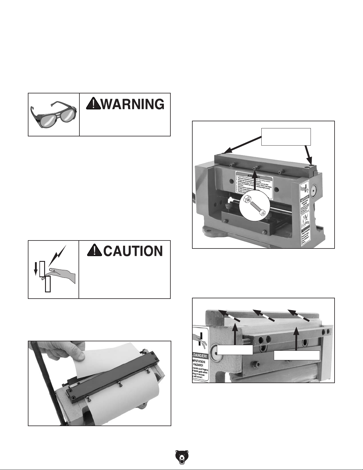
Adjusting Fixed Knife
The fixed (top) knife should be positioned against
the shearing (bottom) knife to achieve a snug and
consistent knife rub without causing the knives to
bind at any location. Misalignment of the knives
can result in machine damage and poor cutting
results.
Eye injury hazard! Always
wear safety glasses when
servicing machine.
Items Needed Qty
Safety Glasses ...........................................1 Pair
Light Machine Oil............................... As Needed
Scrap Paper
Wrench or Socket 3mm
Hex Wrench 4mm
Protective Gloves........................................1 Pair
...................................... As Needed
..................................... 1
.............................................. 1
— If shear cuts paper without binding, no
adjustment is required.
— If shear cuts paper poorly or if knives bind,
proceed to Step 3.
Loosen (2) knife retaining cap screws shown
3.
in Figure 29.
Loosen (3) cap screws with jam nuts shown
4.
in Figure 29 a full turn.
Knife Retaining
Cap Screws
To adjust fixed knife:
Oil knives with light machine oil.
1.
Make sure no body part is
near knives when shearing
occurs. Failure to follow
this warning may result in
cut or pinch injuries.
2. While keeping fingers clear of knives, shear
sheet of paper to test shearing results (see
Figure 28).
x 3
Figure 29. Fixed knife adjustment components.
While wearing protective gloves, carefully
5.
push fixed knife back and away from shearing knife (see Figure 30).
Fixed Knife
Shearing Knife
Figure 28. Example of using paper to test
shearing results.
T32716 (Mfd. Since 05/21)
Figure 30. Location of knives and direction of
fixed knife travel.
-11-
Page 12
No part of fixed knife should contact or
overlap shearing knife for next step. If
knives overlap, knives or other machine
components may be damaged.
Use handle to lift shearing knife completely.
6.
Adjust cap screws from Step 4 until fixed
7.
knife is flush with shearing knife.
IMPORTANT: Shearing knife should still be
able to move past fixed knife without binding.
When fixed knife is aligned with shearing
8.
knife, tighten jam nuts from Step 4 without
moving cap screws to secure setting.
Tighten screws from Step 3.
9.
Repeat test from Step 2 to check adjustment.
10.
Items Needed Qty
Safety Glasses .............................................1 Pr.
Protective Gloves..........................................1 Pr.
Hex Wrenches 3, 4mm
Light Machine Oil............................... As Needed
To rotate or replace knives:
While wearing protective gloves, remove (4)
1.
knife retainer cap screws, knife retainer, and
fixed knife (see Figure 31).
Remove (2) shearing knife retaining cap
2.
screws and shearing knife (see Figure 31).
x 2
................................1 Ea.
Knife Retainer
x 4
Rotating/Replacing Knives
Both of the knives on the Model T32716 can be
removed and rotated to reveal one of the additional cutting edges. Both knives have four available
cutting edges. However, the position of the upper
and lower knives are not interchangeable. When
all edges on the knives have reached the end of
their usable life, they can be reground by using
wet grinding techniques for SK-4 metal or better.
If sharpening services are not available in your
area, replacement knives are available through
grizzly.com and must be replaced as a set.
Eye injury hazard! Always
wear safety glasses when
servicing machine.
Shearing Knife
Figure 31. Knife removal components.
Rotate or flip knives to expose new cutting
3.
edges, or replace knives.
Lubricate knives, then re-install shearing
4.
knife with (2) cap screws removed in Step 2.
Re-install fixed knife and secure in place with
5.
knife retainer and (4) cap screws removed in
Step 1.
Refer to Adjusting Fixed Knife on Page 11
6.
to ensure knives are adjusted correctly.
Fixed Knife
-12-
T32716 (Mfd. Since 05/21)
Page 13
45
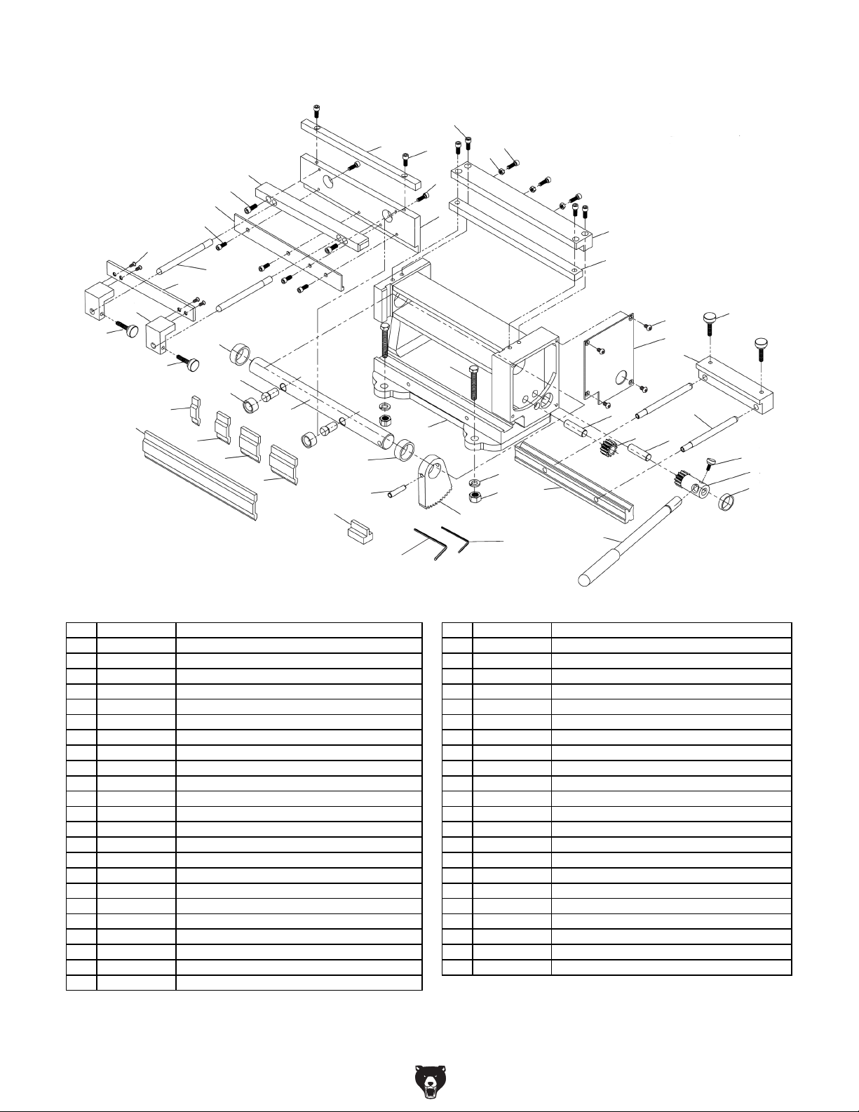
Please Note: We do our best to stock replacement parts whenever possible, but we cannot guarantee that all parts shown here
are available for purchase. Call (800) 523 - 4777 or visit our online parts store at www.grizzly.com to check for availability.
43
14
13
12
42
Parts Breakdown & List
1
7
11
10
3
4
9
2
8
6
21
44
25
34
33
21
22
21
5
36
46
15
16
17
18
19
31
41
25
24
39
32
37
38
47
29
20
23
30
40
29
28
35
REF PART # DES CRIP TI ON REF PART # DES CRIP TI ON
1 PT32716001 CAP SCREW M5-.8 X 25 25 PT32716025 SPACER 22 X 27 X 10
2 PT32716002 CAP SCREW M4-.7 X 25 26 PT32716026 SPACER 19 X 22 X 6
3 PT32716003 HEX NUT M4- . 7 27 PT32716027 P I NI O N GE AR HUB
4 PT32716004 CAP SCREW M5-.8 X 16 28 PT32716028 K NURLE D THUMB SCRE W M4- . 7 X 8, D1 2
5 PT32716005 BALL STUD 29 PT32716029 GEAR PIN 10 X 35
6 PT32716006 FIXED BLADE 30 PT32716030 GEAR
7 PT32716007 SHEARI NG BLADE 31 PT32716031 PI VOT ROD
8 PT32716008 FIXED BLADE RETAINER 32 PT32716032 RA CK A RM
9 PT32716009 SLIDE 33 PT32716033 GEAR COVER
10 PT32716010 CAP SCREW M4-.7 X 10 34 PT32716034 PHLP HD SCR M4-. 7 X 8
11 PT32716011 SHEAR STOP ANCHOR PLATE 35 PT32716035 HE X WRE NCH 4MM
12 PT32716012 CAP SCREW M5-.8 X 12 36 PT32716036 HEX BOLT M10-1.5 X 70
13 PT32716013 FI NG ER GI B 37 PT32716037 FLAT WASHER 10MM
14 PT32716014 CAP SCREW M5-.8 X 12 38 PT32716038 HEX NUT M10 -1. 5
15 PT32716015 FI NG ER 8" 39 PT32716039 BODY
16 PT32716016 FINGER 3/8" 40 PT32716040 BRAKE STOP ROD
17 PT32716017 FINGER 9/16" 41 PT32716041 FINGER SEATING TOOL
18 PT32716018 FINGER 13/16" 42 PT32716042 SHEAR STOP ROD
19 PT32716019 FINGER 1-9/16" 43 PT32716043 SHEAR STOP
20 PT32716020 BENDING PRI SM 44 PT32716044 SHEAR STOP MOUNTI NG BRACKET
21 PT32716021 K NURLE D THUMB SCRE W M5- . 8 X 20 , D16 45 PT32716045 FL AT HD S CR M5-. 8 X 8
22 PT32716022 BRAKE STOP 46 PT32716046 BUSHI NG
23 PT32716023 HA NDLE 47 PT32716047 HE X WRE NCH 3MM
24 PT32716024 TAPER PIN 6 X 40
27
26
T32716 (Mfd. Since 05/21)
-13-
Page 14

Labels & Cosmetics
REF PART # DES CRIPTION REF PART # DES CRIPTION
104
To reduce risk of serious personal injury when using machine:
1. Read and understand manual before using.
2. Always wear eye protection and protective gloves when
handling sheet metal. Chamfer and deburr sharp metal edges.
3. Never place hands near blades or clamping fingers during
operation.
4. Secure brake to workbench before using.
5. DO NOT exceed rated capacity of machine.
6. DO NOT bend wire or nails.
7. Prevent unauthorized use by children or untrained users.
WARN ING !
101
MODEL T32716
8" BENCHTOP METAL
SHEAR/BRAKE
Specifications
Max. Width: 7-7/8"
Max. Thickness (Mild Steel): 20 Ga.
Min. Reverse Bend: 1/4"
Max. Height of Pan/Box Sides: 5/8"
Min. Radius Bend: ??"
Weight: ?? lbs.
Date
Mfd. for Grizzly in China
Serial Number
102
DANGER!
AMPUTATION
HAZARD!
Keep hands and fingers
out of blade path when
shearing or serious
injury will occur!
103
PINCH HAZARD!
Keep hands away
from clamp area
when clamping or
bending.
101 PT32716101 MACHINE ID LABEL 103 PT32716103 TOUCH-UP PA I NT, GRI ZZLY GRE EN
102 PT32716102 AMPUTATI ON/PINCH LABEL 104 PT32716104 WARNING LABEL
Safety labels help reduce the risk of serious injury caused by machine hazards. If any label comes
off or becomes unreadable, the owner of this machine MUST replace it in the original location
before resuming operations. For replacements, contact (800) 523-4777 or www.grizzly.com.
-14-
T32716 (Mfd. Since 05/21)
Page 15

WARRANTY & RETURNS
Grizzly Industrial, Inc. warrants every product it sells for a period of 1 year to the original purchaser from
the date of purchase. This warranty does not apply to defects due directly or indirectly to misuse, abuse,
negligence, accidents, repairs or alterations or lack of maintenance. This is Grizzly’s sole written warranty
and any and all warranties that may be implied by law, including any merchantability or fitness, for any particular purpose, are hereby limited to the duration of this written warranty. We do not warrant or represent
that the merchandise complies with the provisions of any law or acts unless the manufacturer so warrants.
In no event shall Grizzly’s liability under this warranty exceed the purchase price paid for the product and
any legal actions brought against Grizzly shall be tried in the State of Washington, County of Whatcom.
We shall in no event be liable for death, injuries to persons or property or for incidental, contingent, special,
or consequential damages arising from the use of our products.
The manufacturers reserve the right to change specifications at any time because they constantly strive to
achieve better quality equipment. We make every effort to ensure that our products meet high quality and
durability standards and we hope you never need to use this warranty.
In the event you need to use this warranty, contact us by mail or phone and give us all the details. We will
then issue you a “Return Number,’’ which must be clearly posted on the outside as well as the inside of
the carton. We will not accept any item back without this number. Proof of purchase must accompany the
merchandise.
Please feel free to write or call us if you have any questions about the machine or the manual.
Thank you again for your business and continued support. We hope to serve you again soon.
To
you can
applicable information for
take advantage of this warranty, you must register it at https://www.grizzly.com/forms/warranty, or
scan the QR code below to be automatically directed to our warranty registration page. Enter all
the product.
WARRANTY
Page 16

 Loading...