

Page 1

MODEL T32591
13" SPIRAL CUTTERHEAD
FOR DEWALT PLANERS
INSTRUCTIONS
For questions or help with this product contact Tech Support at (570) 546-9663 or techsupport@grizzly.com
Introduction
The T32591 13" Spiral Cutterhead is designed
to replace the straight-knife cutterhead on the
DeWalt DW735 and DW735X (T22222) Planers.
The total procedure for changing the cutterhead
and reassembling the planer takes approximately
three hours. Read these instructions thoroughly
before beginning. These instructions make reference to many procedures detailed in your planer
manual. Always consult your manual for these
procedures. We strongly recommend using the
new replacement bearings included with the
T32591, even if the existing bearings appear to be
in good condition. Call Technical Support at (570)
546-9663 if you need help.
The Model T32591 13" Spiral Cutterhead is
designed to be used only with the DeWalt
DW735 and DW735X (T22222) Planers. DO
NOT install the T32591 in any other planer
model or make. Doing so could result in
property damage or serious personal injury.
Recommended Tools
Description Qty
Open-End Wrenches 6, 24 mm ...................1 Ea.
Deep Well Sockets 32, 40mm
Retaining Ring Pliers (Internal and External)
Hex Wrench 4mm
Torx Driver T-30 (Included with DW735/X)
Phillips Screwdriver #2
Steel Hammer
Hex Bolt
Heavy Leather Gloves
Wood Board (Minimum 12" Length)
Scrap Cardboard
5
⁄16"-18 x 2 ........................................... 1
.............................................. 1
...................................... 1
................................................... 1
................................1 Pair
............................... As Needed
.....................1 Ea.
.... 1
....... 1
.................. 1
Inventory (Figure 1)
Description Qty
A. Ball Bearing 6202-2NSE ............................ 1
Ball Bearing 6204-2NSE ............................ 1
B.
Flat Hd Torx Screws T-25 10-32 x ½" ........ 5
C.
Indexable Inserts 15 x 15 x 2.5mm ............ 5
D.
T-Handle Torx Driver T-25 .......................... 1
E.
Helical Pinion Gear 8T ............................... 1
F.
Spiral Cutterhead 13" ................................. 1
G.
Specifications
Maximum Width of Cut
Cutterhead Diameter
Number of Cutter Rows
Total Number of Indexable Cutters
................................... 13"
..................................... 17⁄8"
..................................... 3
COPYRIGHT © MAY, 2021 BY GRIZZLY INDUSTRIAL, INC.
NO PORTION OF THIS MANUAL MAY BE REPRODUCED IN ANY SHAPE
OR FORM WITHOUT THE WRITTEN APPROVAL OF GRIZZLY INDUSTRIAL, INC.
(FOR MODELS MFD. SINCE 05/21) #KS21865 PRINTED IN TAIWAN
.................. 30
C
A B
F
E
Figure 1. Model T32591 Inventory.
D
G
V1.05.21
Page 2
Cutterhead knives and inserts are razor
sharp! Always wear heavy leather gloves
when handling cutterheads, and avoid
contact with knives and inserts whenever
possible. Failure to comply can result in
serious personal injury.
Removing Existing Cutterhead
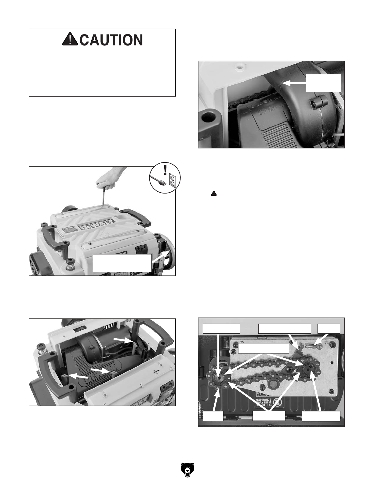
1. DISCONNECT MACHINE FROM POWER.
2. Use T-30 Torx driver included with DW735/X
to remove screws holding top cover (see
Figure 2).
4.
Rotate dust shroud away from cutterhead so
alignment arrow on fan housing aligns with
OPEN line on dust shroud (see Figure 4).
Alignment
Arrow
Figure 4. Alignment arrow on dust shroud.
Pull dust shroud away from fan housing and
5.
remove.
CAUTION: Cutterhead will be exposed at
this time.
Depth Adjustment
Crank Handle
Figure 2. Removing top cover.
Remove red wing nuts holding dust shroud
3.
and set aside (see Figure 3).
. Remove gearbox cover located behind turret
6
lock on left side of planer.
Remove external retaining rings on front and
7.
rear rollers (see Figure 5).
Remove spring from chain tensioner (see
8.
Figure 5).
Remove sprockets and chain (see Figure 5).
9.
Remove spacer on front roller (see Figure 5).
10.
Rear Roller Spring
Retaining Rings
Chain Tensioner
-2-
Figure 3. Location of red wing nuts.
Chain
Figure 5. Gearbox area components.
Sprockets
Model T32591 (Mfd. 05/21)
Front Roller
Page 3

11.
Remove depth adjustment crank handle on
right side of planer.
Remove pulley cover.
12.
13. Remove chain tensioner assembly (see
Figure 6).
Remove sprockets and chain (see Figure 6).
14.
Chain Tensioner Assembly
Cutterhead Pulley
Press cutterhead lock lever and rotate
18.
cutterhead until T-30 Torx screws are visible
on knife clamp (see Figure 8).
Torx Screw
Figure 8. T-30 Torx screws on knife clamp.
Remove screws securing knife clamp.
19.
Sprockets
Figure 6. Pulley area components.
15. Press cutterhead lock lever down to allow
cutterhead to rotate (see Figure 7).
Cutterhead
Lock Lever
Figure 7. Cutterhead lock lever.
Remove drive belt by slowly rotating
16.
cutterhead pulley counterclockwise and pulling belt off. Use rear roller to secure belt after
removal.
Chain
Note: T-30 Torx driver included with DW735/X
has magnets built into handle.
Attract knife clamp with magnet and remove.
20.
21. Attract knife with magnet and remove.
22. Repeat Steps 18–21 until all three knives
have been removed from cutterhead.
Remove cutterhead lock lever and spring
23.
underneath that is hidden from view.
Note: Cutterhead lock lever is not compat-
ible with the Model T32591, but should be
retained in the event planer is ever returned
to original configuration.
Unfasten gearbox attachment screws (see
24.
Figure 9).
Cover table under cutterhead carriage with
17.
scrap cardboard to protect surface from
dropped parts/tools.
Model T32591 (Mfd. 05/21)
Figure 9. Gearbox attachment screws.
-3-
Page 4

25. While supporting gearbox, turn speed selector switch on front panel clockwise to release
(see Figure 10).
Note: Gearbox will separate from planer after
turning speed selector switch to speed "2".
Speed Selector
Switch
Remove helical pinion gear from cutterhead
28.
(see Figure 12).
Remove retaining ring (see Figure 12).
29.
Helical Pinion
Gear
Retaining
Ring
Figure 12. Helical pinion gear and retaining ring.
Figure 10. Supporting gearbox while turning
speed selector switch.
26.
Pull gearbox out and rest it on planer mount.
Note: Gearbox speed selection rod and posi-
tioning pin will prevent gearbox from being
completely removed from planer. Secure
gearbox to planer with tape or rope to prevent
it from shifting during disassembly.
Insert a wood board at least 12" in length
27.
between cutterhead and cutterhead carriage
(see Figure 11). Verify cutterhead no longer
rotates.
Remove 24mm hex nut from cutterhead pul-
30.
ley (see Figure 13).
Remove cutterhead pulley, key, and spacer
31.
(see Figure 13).
Spacer
Figure 13. Cutterhead pulley assembly.
32.
Remove retaining ring from right bearing
bore.
Key
Cutterhead
Pulley
24mm
Nut
Figure 11. Wood board between cutterhead and
carriage.
-4-
Model T32591 (Mfd. 05/21)
Page 5

33. Install 5⁄16"-18 x 2 hex bolt into helical pinion
gear threads (see Figure 14).
. Remove wood board and gently tap hex bolt
34
dead center with hammer until cutterhead is
unseated from carriage (see Figure 14).
Hex Bolt
Figure 14. Hex bolt in helical gear threads.
. Remove spiral cutterhead from packaging.
1
Lightly oil left and right bearing bore surfaces
2.
and remove any dust or dirt.
Lower cutterhead into carriage while guiding
3.
threaded end through right bearing bore (see
Figure 16).
Pull cutterhead through right bearing bore.
35.
36. Use a 32mm deep well socket or wood block
to remove left bearing from bore.
Note: Focus impact to bearing on outer race
(see Figure 15). Take care not to damage
rubber seal.
Outer Race
Rubber
Seal
Inner Race
Figure 15. Bearing outer race.
Figure 16. Example of guiding cutterhead.
. Install 5⁄16"-18 x 2 hex bolt into helical pinion
4
gear threads.
Seat 6202-2NSE ball bearing into left bearing
5.
bore using hex bolt as an alignment guide.
Use a 32mm deep well socket or wood block
6.
to gently tap bearing into bore until retaining
ring groove is visible. Bearing will be flush
with internal carriage wall when fully seated.
Note: If using a wood block to install bear-
ings, ensure that impact is evenly distributed
around outer race to prevent bearing tilt (see
Figure 17).
1
Installing T32591 Spiral Cutterhead
We strongly recommend using the new replacement bearings included with the Model T32591,
even if the existing bearings appear to be in good
condition.
Wrap the new bearings and place them in a freezer overnight. This will cause the bearing metal to
contract, making them easier to install.
Model T32591 (Mfd. 05/21)
4
3
Figure 17. Bearing impact distribution.
Re-install retaining ring into bearing bore
7.
groove.
2
-5-
Page 6

8. Seat 6204-2NSE ball bearing into right bearing bore using threaded cutterhead end as an
alignment guide.
Gently stretch drive belt over cutterhead pul-
17.
ley while slowly rotating pulley clockwise until
belt is centered.
Use a 40mm deep well socket or wood block
9.
to gently tap bearing into bore until retaining
ring groove is visible. Bearing will be flush
with internal carriage wall when fully seated.
Re-install retaining ring into bearing bore
10.
groove.
Insert a wood board at least 12" in length
11.
between cutterhead and cutterhead carriage.
Verify cutterhead no longer rotates.
Install spacer, key, and cutterhead pulley
12.
onto cutterhead end (see Figure 18).
Spacer
Key
Cutterhead
Pulley
24mm
Nut
Note: Drive belt and pulley wheels have
grooves along their surface for alignment.
Verify drive belt is centered on cutterhead
18.
and drive pulleys before re-installing drive
belt cover.
Turn speed selector switch clockwise to
19.
speed "2".
Re-install gearbox by aligning both locating
20.
pins on gearbox assembly with both alignment holes on planer (see Figure 20).
Alignment
Holes
Figure 18. Cutterhead pulley assembly.
Re-install 24mm hex nut on cutterhead pulley.
13.
14. Remove hex bolt and install helical pinion
gear.
Remove wood board.
15.
16. Remove drive belt cover located on right side
(see Figure 19) and verify that drive belt is
centered on drive wheel.
Locating
Pins
Figure 20. Gearbox locating pin alignment.
While installing gearbox, confirm that "U"
21.
bracket attached to speed selector switch
engages with positioning pin on gearbox
speed selection rod (see Figure 21).
Note: If gearbox does not fully seat during
Steps 20–21, slowly rotate cutterhead pulley
back-and-forth to re-align helical pinion gear
with gearbox.
"U"
Bracket
-6-
Figure 19. Drive belt cover location.
Speed
Selector Rod
Figure 21. Speed selector rod and "U" bracket.
Model T32591 (Mfd. 05/21)
Page 7
22. Turn speed selector switch counterclockwise
to speed "1" to grasp positioning pin with "U"
bracket.
Re-install screws removed from gearbox in
23.
Step 24 on Page 3 of Removing Existing
Cutterhead instructions.
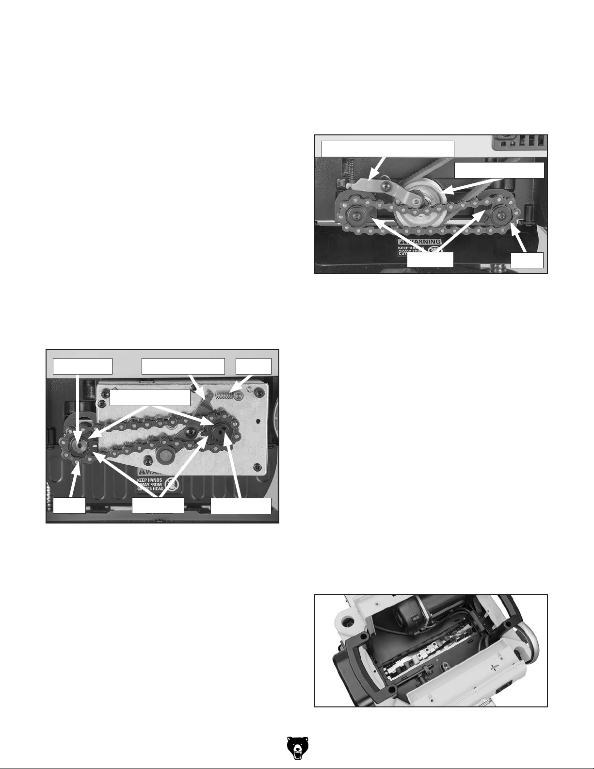
30.
Re-install sprockets and chain on front and
rear rollers in pulley area (see Figure 23).
Re-install chain tensioner and re-attach
31.
spring. Verify tensioner is engaged with chain
(see Figure 23).
Test for smooth operation of speed selection
24.
assembly by cycling speed selector switch
from "1" to "2" and then back to "1".
Re-install spacer on front roller.
25.
26. Re-install sprockets and chain on front and
rear rollers (see Figure 22).
Re-attach spring to chain tensioner. Verify
27.
tensioner is engaged with chain, as shown in
Figure 22.
Re-install retaining rings on front and rear
28.
rollers (see Figure 22).
Rear Roller Spring
Retaining Rings
Chain Tensioner
Chain Tensioner Assembly
Cutterhead Pulley
Sprocket
Figure 23. Pulley area components.
Re-install pulley cover.
32.
33. Re-install dust shroud into fan housing.
Note: DO NOT re-install cutterhead lock
lever! Cutterhead lock lever is not compatible
with the Model T32591.
Rotate dust shroud towards cutterhead.
34.
Verify alignment arrow on fan housing aligns
with CLOSED line on dust shroud.
Chain
Chain
Figure 22. Gearbox area components.
Re-install gearbox cover.
29.
Sprockets
Front Roller
Re-install red wing nuts on dust shroud.
35.
Re-install top cover.
36.
Remove any cardboard used to protect plan-
37.
er table.
Connect machine to power and follow all
38.
procedures outlined in your planer manual for
adjustment and calibration.
Figure 24. Cutterhead installed in planer.
Model T32591 (Mfd. 05/21)
-7-
Page 8

REF PART # DES CRIP TIO N
Please Note: We do our best to stock replacement parts whenever possible, but we cannot guarantee that all parts shown here
are available for purchase. Call (800) 523 -4777 or visit our online parts store at www.grizzly.com to check for availability.
Rotating/Replacing Indexable Inserts
Items Needed:
Heavy Leather Gloves ................................ 1 Pair
T-Handle Torx Driver T-25
T-30 Torx Driver (Included with DW735/X)
Torque Wrench 0–50 in.-lb.
Clean Shop Rags
Degreaser
.......................................... As Needed
.............................. As Needed
Light Machine Oil............................... As Needed
................................. 1
....... 1
............................... 1
Note: Proper cleaning is critical to achiev-
ing a smooth finish. Contaminants trapped
between the insert and cutterhead will slightly
raise the insert, making noticeable marks on
your workpieces the next time you plane.
Lubricate Torx screw threads with a light
5.
machine oil, wipe excess oil off threads, and
torque screw to 48–50 inch/pounds.
The Model T32591 is equipped with 30 indexable
carbide inserts. Each insert can be rotated to
reveal any one of its four cutting edges. If one
cutting edge becomes dull or damaged, rotate it
90˚ to reveal a fresh cutting edge (see Figure 25).
Reference Dot
Figure 25. Rotating indexable insert.
Each insert has a reference dot on one corner.
As the insert is rotated, the reference dot location
can be used as an indicator of which edges are
used and which are new. When the reference dot
revolves back to its starting position, the insert
should be replaced.
6. Return planer to its original configuration by
following Steps 34–39 on Page 7 of Installing
T32591 Spiral Cutterhead instructions.
Accessories
T32861—10 Pack of Indexable Carbide Inserts
Replacement indexable carbide inserts for T32591
13" Spiral Cutterhead.
Parts Breakdown & List
3
5
6
7
4
1
2
To rotate or replace an indexable insert:
DISCONNECT MACHINE FROM POWER.
1.
Gain access to cutterhead by perform-
2.
ing Steps 2–6 of Removing Existing
Cutterhead instructions.
Remove Torx screw and indexable insert.
3.
1 PT32591001 SPI RAL CUTTERHEAD 13"
2 PT32591002 CARBIDE INSERT 15 X 15 X 2.5MM (10PK)
3 PT32591003 FLAT HD TORX SCR T-25 10-32 X 1/2
4 PT32591004 BALL BEARING 6204-2NSE
5 PT32591005 T- HANDL E TO RX DRI VER T-25
6 PT32591006 HELICAL PINION GEAR 8T
7 PT32591007 BALL BEARING 6202-2NSE
4. Clean all dust and dirt off insert and cutterhead
pocket from which insert was removed, and
replace insert so a fresh, sharp edge is facing
outward.
-8-
Model T32591 (Mfd. 05/21)
 Loading...