

Page 1
MODEL T32057
8" HELICAL CUTTERHEAD
ASSEMBLY FOR G0855
INSTRUCTIONS
For questions or help with this product contact Tech Support at (570) 546-9663 or techsupport@grizzly.com
Introduction
The Model T32057 8" Helical Cutterhead is
designed to replace the straight-knife cutterhead
on the Model G0855 8" x 72" Jointer.
DO NOT modify or alter this cutterhead to
make it fit other makes or models of jointers for which it is not designed. Doing so
could result in property damage or serious
personal injury.
The total installation/setup procedure takes
approximately half an hour. Read these instructions thoroughly before beginning.
Note: Not all pictures in these instructions will
exactly reflect your machine. Some photos are
provided for representation purposes only to help
you better understand the instructions given.
Specifications
Maximum Width of Cut ...................................... 8"
Cutterhead Diameter
Number of Indexable Carbide Inserts
Indexable Carbide Insert Size
.....................................31⁄16"
.............. 36
.... 15 x 15 x 2.5mm
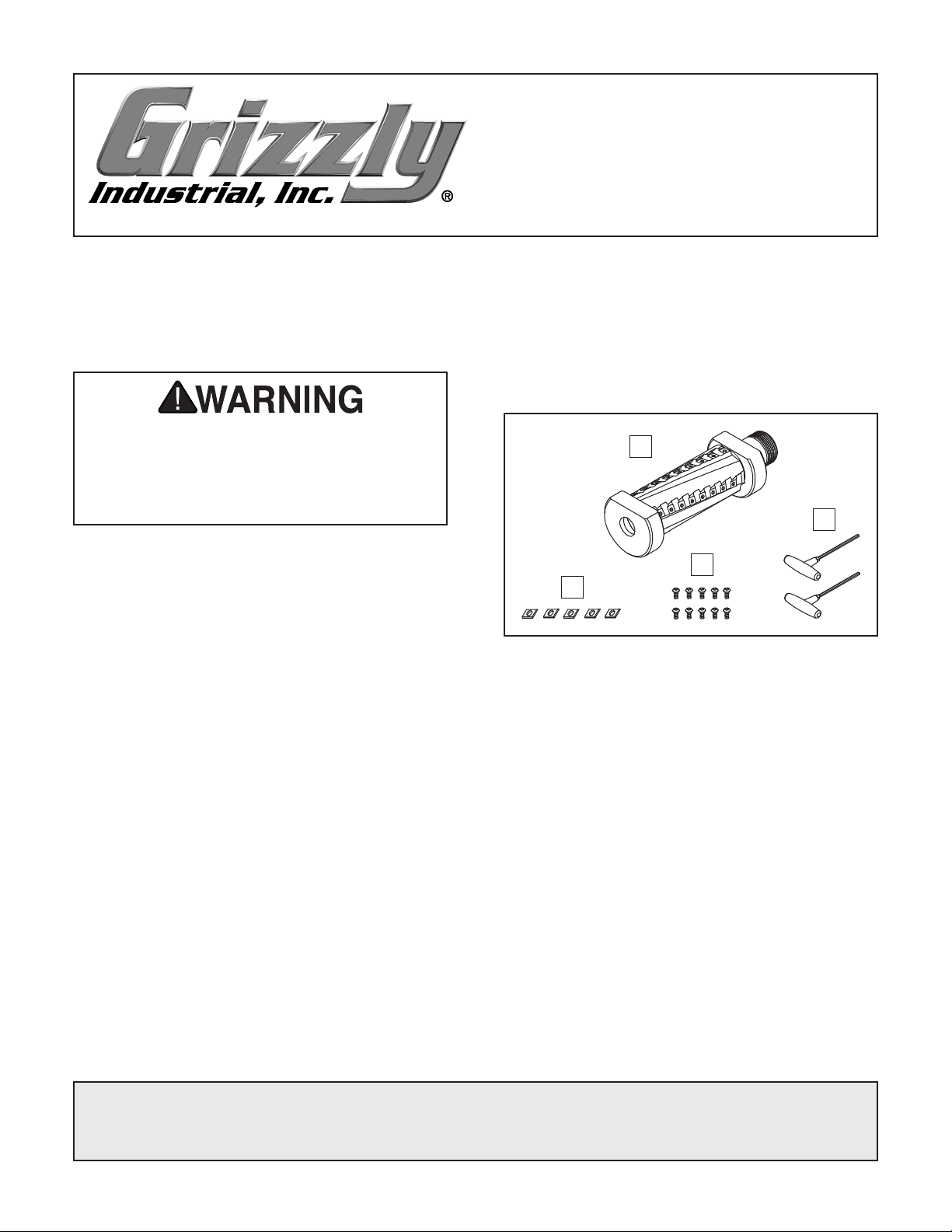
Inventory (Figure 1)
Description Qty
A. Helical Cutterhead Assembly ...................... 1
T-Handle Torx Drivers T25 .......................... 2
B.
Flat Hd Torx Screws T25 10-32 x 1⁄2" ........ 10
C.
Indexable Inserts 15 x 15 x 2.5mm ............. 5
D.
A
B
C
D
Figure 1. Model T32057 inventory.
Tools Needed
• Pair of Heavy Leather Gloves ..................... 1
Safety Glasses (per person) ........................ 1
•
Phillips Head Screwdriver #2 ...................... 1
•
Flat Head Screwdriver ................................. 1
•
Adjustable Wrench ...................................... 1
•
Precision Straightedge 36" .......................... 1
•
Feeler Gauge Set ........................................ 1
•
Shop Rag .................................... As Needed
•
Degreaser .................................... As Needed
•
COPYRIGHT © MAY, 2020 BY GRIZZLY INDUSTRIAL, INC.
WARNING : NO PORTION OF THIS MANUAL MAY BE REPRODUCED IN ANY SHAPE
OR FORM WITHOUT THE WRITTEN APPROVAL OF GRIZZLY INDUSTRIAL, INC.
(FOR MODELS MFD. SINCE 04/20) #KS21092 PRINTED IN TAIWAN
V1.0 5.20
Page 2
Removing Existing Cutterhead
1. DISCONNECT MACHINE FROM POWER!
Remove jointer fence, cutterhead guard, and
2.
rabbeting table.
Remove rear access panel and belt cover,
3.
then remove V-belt from pulleys.
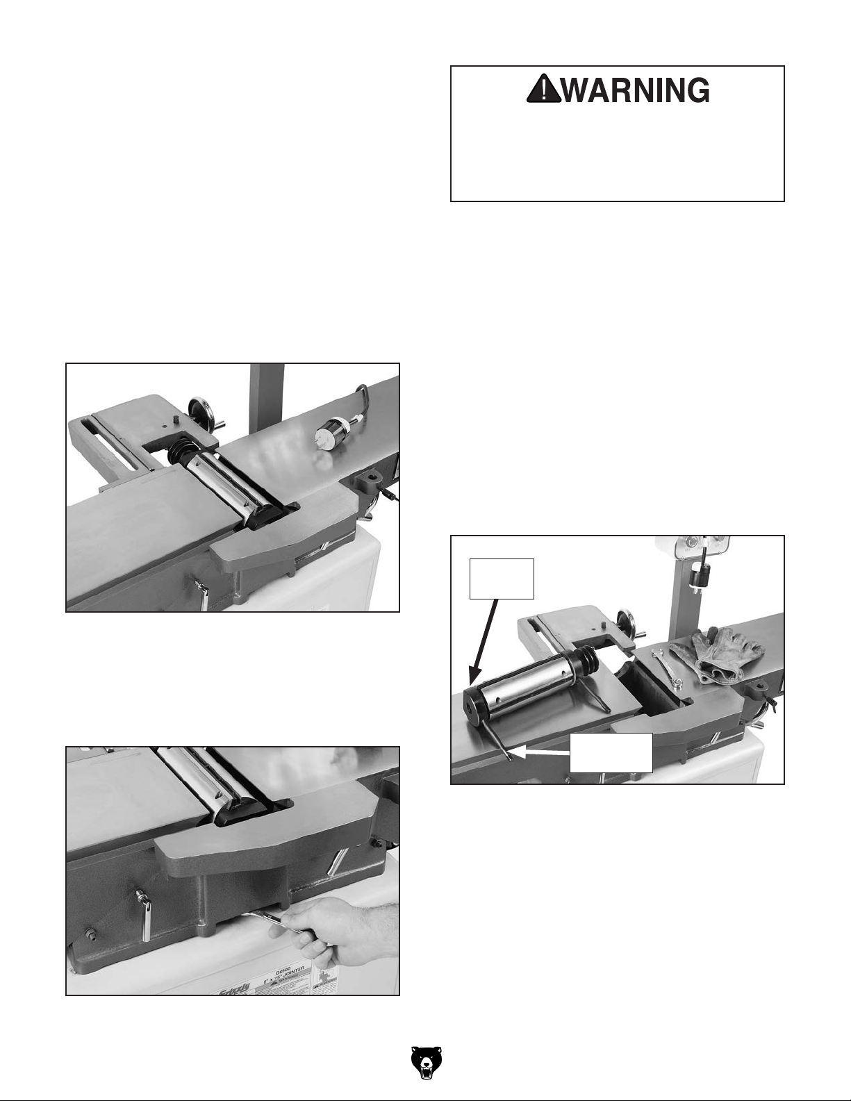
Lower both tables to make enough room for
4.
the cutterhead to come out (see Figure 2).
Jointer knives are extremely sharp. You
must remove the jointer knives, or mount
the knives blade side down to avoid the risk
of serious personal injury during the following steps.
Wearing heavy leather gloves, carefully
6.
remove the cutterhead from the casting (see
Figure 4).
Note: When lowering, make sure that the
fence support does not come in contact with
the cutterhead pulley.
Figure 2. Example of jointer disassembly Steps
4.
1–
5. Remove nut and flat washer on bearing block
stud, as shown in Figure 3, and repeat on the
other side.
Note: Your cutterhead may have paper shims
stuck to the bearing block or where the bearing block rests. These were included at the
factory when they calibrated your cutterhead
to be even with the outfeed table. Your new
cutterhead may or may not need these. If
you see any shims, carefully pull them off
and set them aside for later use—or keep
them with your cutterhead in the event that
you re-install it later. Also, mark the side of
the cutterhead where they were used, so the
future install will go smoothly.
Bearing
Block
Figure 3. Example of removing hex nut and flat
washer on bearing block stud.
-2-
Bearing
Block Stud
Figure 4. Example of cutterhead removed.
Remove bearing block studs from bearing
7.
blocks.
T32057 8" Helical Cutterhead Assembly
Page 3
Installing Helical Cutterhead
Jointer carbide inserts are extremely sharp.
Wear leather gloves to avoid the risk of
serious personal injury during the following
steps.
1. Install cutterhead (see Figure 5) with bearing
block studs, flat washers, and hex nuts previously removed.
Figure 5. Example of helical cutterhead installed.
Tighten helical cutterhead in place, and
2.
ensure pulley set screw is tight.
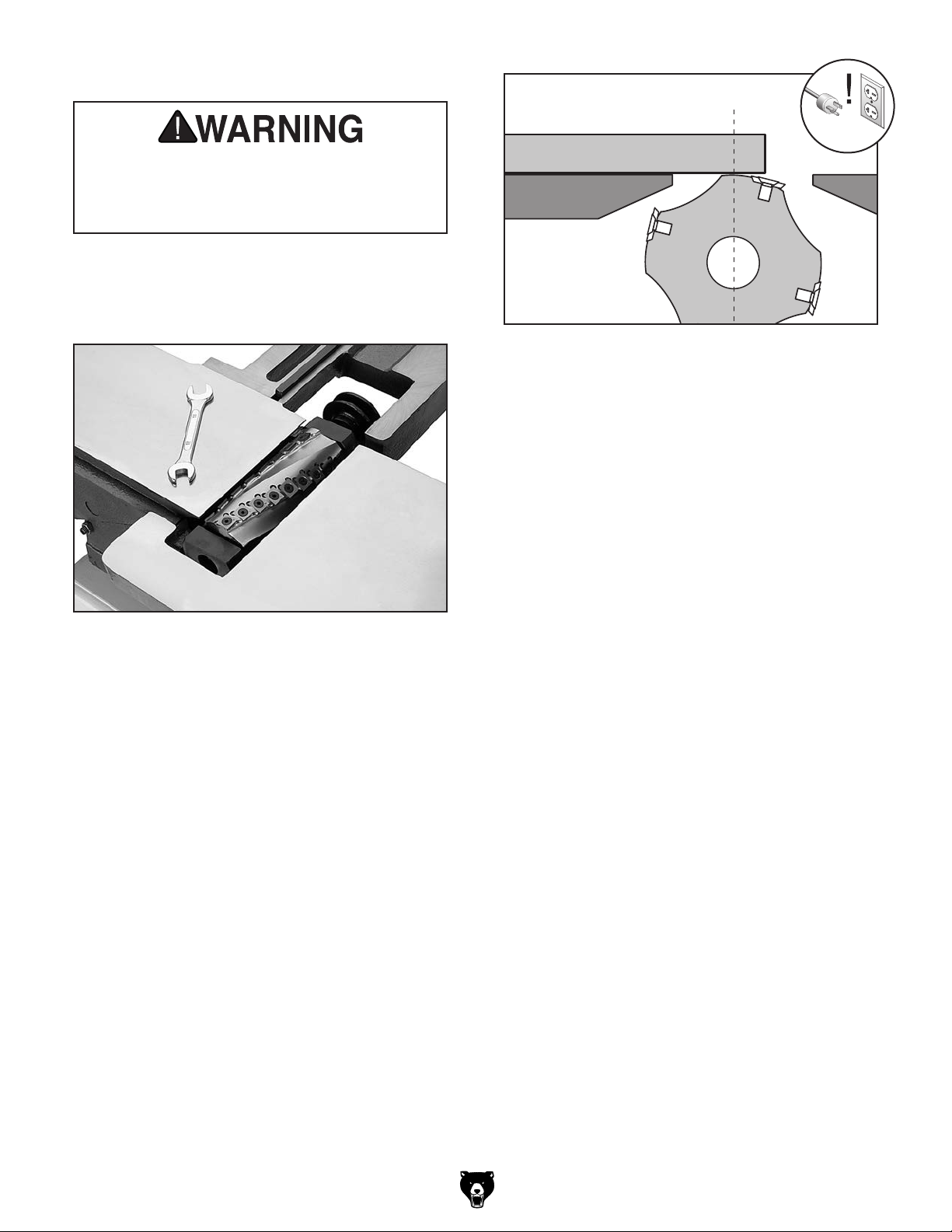
. Using straightedge and feeler gauge set,
3
inspect cutterhead parallelism with outfeed
table as shown in Figure 6. With straightedge
in position, raise or lower outfeed table until
cutterhead body (not the carbide insert) just
touches straightedge.
Straightedge
Outfeed Table
Figure 6. Checking cutterhead parallelism.
Move straightedge to the other side to deter-
4.
mine if one end of cutterhead body is higher/
lower than the other. (Place feeler gauge
between cutterhead body and straightedge to
determine the height difference.)
If cutterhead is even or within 0.003" with
—
outfeed table from one side to other, skip
to Step 7.
If cutterhead is over 0.003" from one side
—
to other, go to Step 5.
Loosen hex nuts securing both bearing block
5.
studs, lift helical cutterhead slightly, then
place a shim beneath bearing block that
needs to be adjusted.
Note: Use shims from your old cutterhead
if available. If not available, newspaper is
approximately 0.003" thick and will work for
shimming (we don't recommend shimming
more than 0.003" on either side, as this may
affect how the bearing block seats in the
casting).
T32057 8" Helical Cutterhead Assembly
Repeat Steps 3–5 and adjust as necessary,
6.
then tighten hex nuts on bearing block studs.
-3-
Page 4

7. Place a straightedge on outfeed table
so it extends over cutterhead, and rotate
cutterhead pulley until one of the carbide
inserts is at top-dead-center (TDC), as shown
in Figure 7.
Straightedge
Outfeed Infeed
Figure 7. Cutterhead insert at top-dead-center.
When correctly set, carbide insert will just
touch straightedge when insert is at its highest point of rotation (see Figure 7).
Lock outfeed table, then re-install fence.
8.
Re-install V-belt on pulleys. (Refer to instruc-
9.
tions in your G0855 manual for details.)
Re-install rabbeting table, rear access panel,
10.
and belt cover.
Install cutterhead guard back over cutterhead,
11.
making sure that spring tension in guard
is properly set so guard springs back over
cutterhead when it is pulled back and
released.
— If your outfeed table is correctly set, no
adjustments are necessary.
— If insert lifts straightedge off table or if
table is below straightedge, adjust outfeed
table height with handwheel until straightedge just touches an insert at its highest
point of rotation.
-4-
T32057 8" Helical Cutterhead Assembly
Page 5
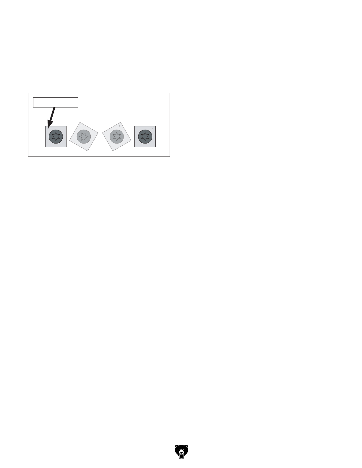
Rotating Inserts
The cutterhead is equipped with 36 indexable carbide inserts. Each insert can be rotated to reveal
any one of its four cutting edges. Therefore, if one
cutting edge becomes dull or damaged, simply
rotate it clockwise 90˚ to reveal a fresh cutting
edge (see Figure 8).
Reference Dot
Figure 8. Rotating indexable carbide inserts.
In addition, each insert has a reference dot on
one corner. As the insert is rotated, the reference
dot location can be used as an indicator of which
edges are used and which are new. The insert
must be replaced when all four edges are dull.
Tools Needed
• Pair of Heavy Leather Gloves ..................... 1
Safety Glasses (per person) ........................ 1
•
T-Handle Torx Driver T25 ........................... 1
•
Torque Wrench 0–50 in.-lb. ......................... 1
•
Shop Rag .................................... As Needed
•
Degreaser .................................... As Needed
•
Light Machine Oil ........................ As Needed
•
Installing or adjusting a carbide insert:
1. DISCONNECT MACHINE FROM POWER!
Remove any sawdust from head of carbide
2.
insert Torx screw.
3. Remove Torx screw and carbide insert.
Clean all dust and dirt off insert and cutterhead
4.
pocket from which insert was removed, and
replace insert so a fresh, sharp edge is facing
outward.
Note: Proper cleaning is critical to achiev-
ing a smooth finish. Dirt or dust trapped
between insert and cutterhead will slightly
raise insert, and make noticeable marks on
your workpieces the next time you cut.
Lubricate Torx screw threads with a light
5.
machine oil, wipe excess oil off threads, and
torque Torx screw to 48-50 INCH pounds.
Note: Excess oil may squeeze between insert
and cutterhead or in screw hole, thereby lifting
insert or screw slightly and affecting workpiece finishes.
T32057 8" Helical Cutterhead Assembly
-5-
Page 6

Accessories
H9893—10 Pack of Indexable Carbide Inserts
Replacement 15 x 15 x 2.5mm carbide inserts for
Model T32057 8" Helical Cutterhead.
Figure 9. H9893 Indexable Carbide Inserts.
Basic Eye Protection
T20501—Face Shield Crown Protector 4"
T20502—Face Shield Crown Protector 7"
T20503—Face Shield Window
T20451—“Kirova” Clear Safety Glasses
T20452—“Kirova” Anti-Reflective S. Glasses
T20456—DAKURA Safety Glasses, Black/Clear
G0860—1½ HP Portable Cyclone Dust Collector
This compact unit features an impressive 868
CFM and up to 9.7" of static pressure —perfect
for handling up to two large machines at once.
The 20 gallon collection drum with quick release
handle catches large particulate for quick and
clean bag changes, and the pleated 1-micron filter
captures remaining dust as part of this super efficient two stage separation system. All this, and it
features a wireless remote!
Figure 11. G0860 Portable Dust Collector.
T20502
T20503
T20456
Figure 10. Assortment of basic eye protection.
T20452
T20451
-6-
T32057 8" Helical Cutterhead Assembly
Page 7
5
REF PART # DESCRIPTION REF PART # DESCRIPTION
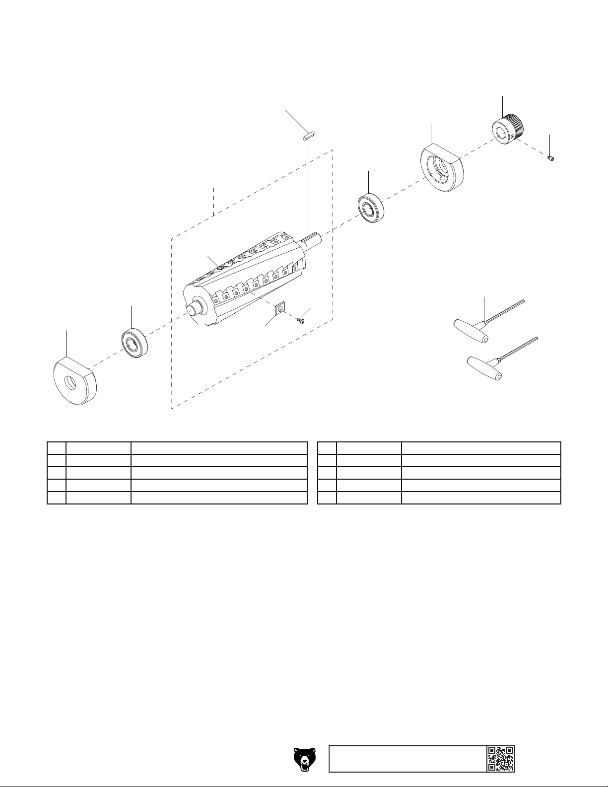
T32057 Parts Breakdown & List
We do our best to stock replacement parts when possible, but we cannot guarantee that all parts shown
are available for purchase. Call (800) 523-4777 or visit www.grizzly.com/parts to check for availability.
4
1
2
3
3-1
6
2
1
3-3
1 PT32057001 BEARING BLOCK 3-3 PT32057003-3 INSERTS 15 X 15 X 2.5MM-10 PK
2 PT32057002 BALL BEARING 6204-2NSE 4 PT32057004 KEY 5 X 5 X 30 RE
3 PT32057003 HELICAL CUTTERHEAD ASSEMBLY 5 PT32057005 CUTTERHEAD PULLEY
3-1 PT32057003-1 CUTTERHEAD 8" HELICAL 6 PT32057006 SET SCREW M6-1 X 8
3-2 PT32057003-2 FLAT HD TORX SCR T-25 10-32 X 1/2 7 PT32057007 T-HANDLE TORX DRIVER T-25
3-2
7
T32057 8" Helical Cutterhead Assembly
T32057 8" Helical Cutterhead Assembly
BUY PARTS ONLINE AT GRIZZLY.COM!
Scan QR code to visit our Par ts Store.
-7-
-7-
Page 8

 Loading...