

Grizzly T28192 Owner's Manual

MODEL T28192
20" 6.5-TON LOG SPLITTER
OWNER'S MANUAL
(For models manufactured since 04/18)
COPYRIGHT © MAY, 2018 BY GRIZZLY INDUSTRIAL, INC.
WARNING : NO PORTION OF THIS MANUAL MAY BE REPRODUCED IN ANY SHAPE
OR FORM WITHOUT THE WRITTEN APPROVAL OF GRIZZLY INDUSTRIAL, INC.
#ESAB19473 PRINTED IN CHINA
V1. 0 5 .18

This manual provides critical safety instructions on the proper setup,
operation, maintenance, and service of this machine/tool. Save this
document, refer to it often, and use it to instruct other operators.
Failure to read, understand and follow the instructions in this manual
may result in fire or serious personal injury—including amputation,
electrocution, or death.
The owner of this machine/tool is solely responsible for its safe use.
This responsibility includes but is not limited to proper installation in
a safe environment, personnel training and usage authorization,
proper inspection and maintenance, manual availability and comprehension, application of safety devices, cutting/sanding/grinding tool
integrity, and the usage of personal protective equipment.
The manufacturer will not be held liable for injury or property damage
from negligence, improper training, machine modifications or misuse.
Some dust created by power sanding, sawing, grinding, drilling, and
other construction activities contains chemicals known to the State
of California to cause cancer, birth defects or other reproductive
harm. Some examples of these chemicals are:
• Lead from lead-based paints.
• Crystalline silica from bricks, cement and other masonry products.
• Arsenic and chromium from chemically-treated lumber.
Your risk from these exposures varies, depending on how often you
do this type of work. To reduce your exposure to these chemicals:
Work in a well ventilated area, and work with approved safety equipment, such as those dust masks that are specially designed to filter
out microscopic particles.

Table of Contents
INTRODUCTION ............................................... 2
Contact Info.................................................... 2
Manual Accuracy ........................................... 2
Identification ................................................... 3
Controls & Components ................................. 4
Machine Data Sheet ...................................... 5
SECTION 1: SAFETY ....................................... 7
Safety Instructions for Machinery .................. 7
Additional Safety for Log Splitters ................. 9
SECTION 2: POWER SUPPLY ...................... 10
SECTION 3: SETUP ....................................... 12
Needed for Setup ......................................... 12
Unpacking .................................................... 12
Jobsite Considerations................................. 13
Lifting & Moving ........................................... 13
Assembly ..................................................... 13
Test Run ...................................................... 14
SECTION 4: OPERATIONS ........................... 15
Operation Overview ..................................... 15
Using Hydraulic Control Lever ..................... 16
Setting Hydraulic Ram Start Position .......... 16
Splitting Logs ............................................... 16
Removing Stuck Log .................................... 17
SECTION 5: ACCESSORIES ......................... 18
SECTION 6: MAINTENANCE ......................... 20
Schedule ...................................................... 20
Cleaning ....................................................... 20
Lubrication ................................................... 20
Checking/Adding/Changing Hydraulic Fluid 21
Splitting Wedge ............................................ 22
SECTION 7: SERVICE ................................... 23
Troubleshooting ........................................... 23
SECTION 8: WIRING ...................................... 25
Wiring Safety Instructions ............................ 25
Wiring Diagram ............................................ 26
Electrical Components ................................. 26
SECTION 9: PARTS ....................................... 27
Parts Breakdown.......................................... 27
Labels & Cosmetics ..................................... 29
SECTION 10: HYDRAULIC SYSTEM ............ 30
WARRANTY & RETURNS ............................. 33
We stand behind our machines! If you have questions or need help, contact us with the information
below. Before contacting, make sure you get the
serial number
machine ID label. This will help us help you faster.
We want your feedback on this manual. What did
you like about it? Where could it be improved?
Please take a few minutes to give us feedback.
Email: manuals@grizzly.com
We are proud to provide a high-quality owner’s
manual with your new machine!
We
instructions, specifications, drawings, and photographs
in this manual. Sometimes we make mistakes, but
our policy of continuous improvement also means
that
you receive is
slightly different than shown in the manual
If you find this to be the case, and the difference
between the manual and machine leaves you
confused or unsure about something
check our
website for an updated version. W
current
manuals and
on our web-
site at
Alternatively, you can call our Technical Support
for help. Before calling, make sure you write down
the
from
the machine ID label (see below). This information
is required for us to provide proper tech support,
and it helps us determine if updated documentation is available for your machine.
INTRODUCTION
Contact Info
and manufacture date from the
Grizzly Technical Support
1815 W. Battlefield
Springfield, MO 65807
Phone: (570) 546-9663
Email: techsupport@grizzly.com
Grizzly Documentation Manager
P.O. Box 2069
Bellingham, WA 98227-2069
Manual Accuracy
made every effort to be exact with the
sometimes the machine
.
,
e post
manual updates for free
www.grizzly.com.
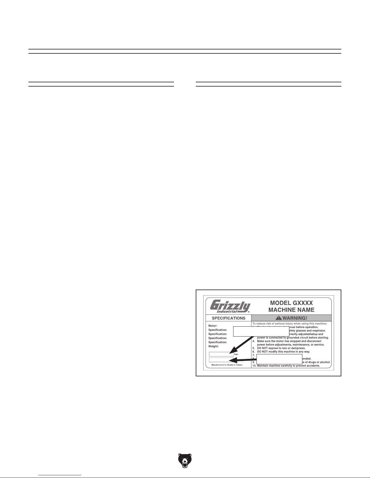
Manufacture Date and Serial Number
Manufacture Date
Serial Number
-2-
Model T28192 (Mfd. Since 04/18)

Identification
To reduce your risk of
serious injury, read this
entire manual BEFORE
Become familiar with the names and locations of the controls and features shown below to better understand
the instructions in this manual.
Air Bleed
Screw
Hydraulic Fluid Tank
Plug w/Dipstick
Hydraulic Ram
Splitting
Log Table
Hydraulic
Control Lever
Hydraulic
Control
Valve
Pressure
Release
Wheels
Wedge
Hydraulic
Fluid Tank
Electric
Motor
Transport
Handle
Hydraulic Ram
Return Stop
Power Switch
Model T28192 (Mfd. Since 04/18)
using machine.
-3-

Controls &
To reduce your risk of
serious injury, read this
entire manual BEFORE
Components
D. ON Button: When pushed and held,
starts and runs motor to pressurize
hydraulic fluid. ON button and hydraulic
control lever must be held simultaneously to
activate hydraulic ram.
E. Hydraulic Control Valve Pressure Release:
Slowly loosen hex bolt to release pressure
inside hydraulic control valve if hydraulic ram
does not return to start position.
using machine.
Refer to the following figures and descriptions to
become familiar with the basic controls and components of this machine. Understanding these
items and how they work will help you understand
the rest of the manual and stay safe when operating this machine.
Controls & Components
A B
F
C
E
D
Figure 1. Controls and components—rear.
F. Hydraulic Control Lever: Push down
to activate hydraulic ram. Hydraulic
control lever and ON button must be pushed
and held simultaneously to activate hydraulic
ram.
G
H
I
L
J
K
Figure 2. Controls and components—front.
G. Splitting Wedge: Stationary high-carbon
steel wedge that splits logs.
H. Air Bleed Screw: Loosen screw slowly to
release air inside hydraulic cylinder.
A. Hydraulic Ram: Drives logs into splitting
wedge. Delivers 6.5 tons of ram force.
B. Log Bed: Supports logs during log splitting
operations.
C. Circuit Breaker Reset Button: Circuit
breaker trips if motor draws excessive current
and overheats. Push to reset circuit breaker
after allowing machine to cool down.
-4-
I. Transport Handle: Allows for easy lifting and
moving of log splitter.
J. Hydraulic Fluid Tank Plug w/Dipstick:
Remove to check fluid level and add/change
hydraulic fluid.
K. Hydraulic Ram Return Stop: Sets start
position for hydraulic ram.
L. Hydraulic Fluid Tank: Holds 3.7 quarts of
ISO 22 or equivalent hydraulic fluid.
Model T28192 (Mfd. Since 04/18)

Machine Data Sheet
machine data sheet
Customer Service #: (570) 546-9663 · To Order Call: (800) 523-4777 · Fax #: (800) 438-5901
MODEL T28192
20" 6.5-TON LOG SPLITTER
Product Dimensions:
...............................................................................................................................
Weight
(side-to-side) x Depth (front-to-back) x Height ...........................................................................37 x 10-1/2 x 19-1/2 in.
Width
Footprint
Shipping Dimensions:
Type
Content
Weight
Length
Must
(Length x Width) ...............................................................................................................................
................................................................................................................................................................... Cardboard Box
...............................................................................................................................
...............................................................................................................................
x Width x Height ...............................................................................................................................
Ship Upright ...............................................................................................................................
............................................... 99
........................................... Machine
............................................. 114
..................................Yes
......33
......38
lbs.
x 9-1/2 in.
lbs.
x 11 x 20 in.
Electrical:
Requirement ........................................................................................................................
Power
Full-Load
Minimum
Connection
Power
Power
Power
Plug
Included
Switch Type ............................................................................................................................................................ Push Button
Motors:
Main
Horsepower
Phase
Amps .................................................................................................................................................................................... 15A
Speed
Type
Power
Bearings
Hydraulic Information:
Hydraulic
Maximum
Hydraulic
Hydraulic
Current Rating ...............................................................................................................................
Circuit Size ...............................................................................................................................
Type ...............................................................................................................................
Cord Included ............................................................................................................................................................Yes
Cord Length ...............................................................................................................................
Cord Gauge ...............................................................................................................................
Included ...............................................................................................................................
Plug Type ...............................................................................................................................
...............................................................................................................................
...............................................................................................................................
...............................................................................................................................
...............................................................................................................................
Transfer ...............................................................................................................................
.............................................................................................................................
Cylinder Size (Width x Length) ....................................................................................................................3 x 32 in.
Pump Pressure ...............................................................................................................................
Tank Capacity ...............................................................................................................................
Fluid Type ......
Shell
Tellus 22, Mobil DTE 11, ARAL Vitam GF 22, BP Energol HLP-HM 22, or ISO 22 equivalent
....................................TEFC
.........................................Yes
.....................................1.75
..................................... Single-Phase
..........................................3450
Shielded
Single-Phase, 60 Hz
120V,
....................... 15A
............................ 15A
...................... Cord
................................6
........................ 14
...............................5-15
.........................Direct
& Permanently Lubricated
............. 3190
....................3.7
& Plug
ft.
AWG
HP
RPM
Induction
Drive
PSI
qt.
Main Specifications:
Operation Information
Splitting
Max.
Cycle
Max.
Automatic
Splitter
Force (Tonnage Rating) ........................................................................................................................
Log Dimensions (Length x Diameter) ......................................................................................................20 x 10 in.
Time ...............................................................................................................................
Stroke Length .................................................................................................................................................. 14 in.
Cylinder Return ...............................................................................................................................
Wedge Height ...............................................................................................................................
Model T28192 (Mfd. Since 04/18)
......................18
...........4-3/4
Tons
6.5
Seconds
...........Yes
in.
-5-

Construction Information
Wedge ...............................................................................................................................
Splitter
...............................................................................................................................
Axle
Bed
...............................................................................................................................
Stand
...............................................................................................................................
Log Cradle .................................................................................................................................................................Steel
Other Specifications:
Country
Warranty
Serial
ISO
Certified
Assembly
Features:
Automatic
20"L
6.5-Ton
Two-Handed
Variable-Adjustment
Carbon-Steel
Steel
Built-In
of Origin ...............................................................................................................................
...............................................................................................................................
Number Location ...............................................................................................................................
9001 Factory ..................................................................................................................................................................Yes
by a Nationally Recognized Testing Laboratory ......................................................................................................
Time ...............................................................................................................................
Cylinder Return
x 10"D Log Capacity
Splitter Ram Pressure
Operation Keeps Hands Clear of Action While Operating
Splitter Wedge
Frame
Wheels for Mobility
of Ram Stroke with Built-In Stop
...............Carbon
.............................................Steel
.............................................Steel
..........................................Steel
................................ China
............................................ 1
................. ID
.......................... 15
Steel
Year
Label
Minutes
No
-6-
Model T28192 (Mfd. Since 04/18)

SECTION 1: SAFETY
For Your Own Safety, Read Instruction
Manual Before Operating This Machine
The purpose of safety symbols is to attract your attention to possible hazardous conditions.
This manual uses a series of symbols and signal words intended to convey the level of importance of the safety messages. The progression of symbols is described below. Remember that
safety messages by themselves do not eliminate danger and are not a substitute for proper
accident prevention measures. Always use common sense and good judgment.
Indicates an imminently hazardous situation which, if not avoided,
WILL result in death or serious injury.
Indicates a potentially hazardous situation which, if not avoided,
COULD result in death or serious injury.
Indicates a potentially hazardous situation which, if not avoided,
MAY result in minor or moderate injury. It may also be used to alert
against unsafe practices.
This symbol is used to alert the user to useful information about
NOTICE
proper operation of the machine.
Safety Instructions for Machinery
OWNER’S MANUAL. Read and understand this
owner’s manual BEFORE using machine.
TRAINED OPERATORS ONLY. Untrained operators have a higher risk of being hurt or killed.
Only allow trained/supervised people to use this
machine. When machine is not being used, disconnect power, remove switch keys, or lock-out
machine to prevent unauthorized use—especially
around children. Make your workshop kid proof!
DANGEROUS ENVIRONMENTS. Do not use
machinery in areas that are wet, cluttered, or have
poor lighting. Operating machinery in these areas
greatly increases the risk of accidents and injury.
MENTAL ALERTNESS REQUIRED. Full mental
alertness is required for safe operation of machinery. Never operate under the influence of drugs or
alcohol, when tired, or when distracted.
ELECTRICAL EQUIPMENT INJURY RISKS. You
can be shocked, burned, or killed by touching live
electrical components or improperly grounded
machinery. To reduce this risk, only allow qualified
service personnel to do electrical installation or
repair work, and always disconnect power before
accessing or exposing electrical equipment.
DISCONNECT POWER FIRST.
nect machine from power supply BEFORE making
adjustments, changing tooling, or servicing machine.
This prevents an injury risk from unintended startup
or contact with live electrical components.
EYE PROTECTION. Always wear ANSI-approved
safety glasses or a face shield when operating or
observing machinery to reduce the risk of eye
injury or blindness from flying particles. Everyday
eyeglasses are NOT approved safety glasses.
Always discon-
Model T28192 (Mfd. Since 04/18)
-7-

WEARING PROPER APPAREL. Do not wear
clothing, apparel or jewelry that can become
entangled in moving parts. Always tie back or
cover long hair. Wear non-slip footwear to reduce
risk of slipping and losing control or accidentally
contacting cutting tool or moving parts.
HAZARDOUS DUST. Dust created by machinery
operations may cause cancer, birth defects, or
long-term respiratory damage. Be aware of dust
hazards associated with each workpiece material. Always wear a NIOSH-approved respirator to
reduce your risk.
HEARING PROTECTION. Always wear hearing protection when operating or observing loud
machinery. Extended exposure to this noise
without hearing protection can cause permanent
hearing loss.
REMOVE ADJUSTING TOOLS. Tools left on
machinery can become dangerous projectiles
upon startup. Never leave chuck keys, wrenches,
or any other tools on machine. Always verify
removal before starting!
USE CORRECT TOOL FOR THE JOB. Only use
this tool for its intended purpose—do not force
it or an attachment to do a job for which it was
not designed. Never make unapproved modifications—modifying tool or using it differently than
intended may result in malfunction or mechanical
failure that can lead to personal injury or death!
AWKWARD POSITIONS. Keep proper footing
and balance at all times when operating machine.
Do not overreach! Avoid awkward hand positions
that make workpiece control difficult or increase
the risk of accidental injury.
CHILDREN & BYSTANDERS. Keep children and
bystanders at a safe distance from the work area.
Stop using machine if they become a distraction.
GUARDS & COVERS. Guards and covers reduce
accidental contact with moving parts or flying
debris. Make sure they are properly installed,
undamaged, and working correctly BEFORE
operating machine.
FORCING MACHINERY. Do not force machine.
It will do the job safer and better at the rate for
which it was designed.
NEVER STAND ON MACHINE. Serious injury
may occur if machine is tipped or if the cutting
tool is unintentionally contacted.
STABLE MACHINE. Unexpected movement during operation greatly increases risk of injury or
loss of control. Before starting, verify machine is
stable and mobile base (if used) is locked.
USE RECOMMENDED ACCESSORIES. Consult
this owner’s manual or the manufacturer for recommended accessories. Using improper accessories will increase the risk of serious injury.
UNATTENDED OPERATION. To reduce the
risk of accidental injury, turn machine OFF and
ensure all moving parts completely stop before
walking away. Never leave machine running
while unattended.
MAINTAIN WITH CARE. Follow all maintenance
instructions and lubrication schedules to keep
machine in good working condition. A machine
that is improperly maintained could malfunction,
leading to serious personal injury or death.
DAMAGED PARTS. Regularly inspect machine
for damaged, loose, or mis-adjusted parts—or
any condition that could affect safe operation.
Immediately repair/replace BEFORE operating
machine. For your own safety, DO NOT operate
machine with damaged parts!
MAINTAIN POWER CORDS. When disconnecting cord-connected machines from power, grab
and pull the plug—NOT the cord. Pulling the cord
may damage the wires inside. Do not handle
cord/plug with wet hands. Avoid cord damage by
keeping it away from heated surfaces, high traffic
areas, harsh chemicals, and wet/damp locations.
EXPERIENCING DIFFICULTIES. If at any time
you experience difficulties performing the intended operation, stop using the machine! Contact our
Technical Support at (570) 546-9663.
-8-
Model T28192 (Mfd. Since 04/18)

Additional Safety for Log Splitters
Serious crushing injury can occur from getting hands or fingers caught between logs and
hydraulic ram/splitting wedge during operation. Pieces of logs can be ejected by log splitter
and strike operator or bystanders, resulting in impact injury, eye injury, or blindness. Death can
result from getting accidentally injected with hydraulic fluid. To minimize risk of injury, anyone
operating this machine MUST completely heed hazards and warnings below.
SUPPORTING LOGS. Never use hands or any
part of your body to support a log when activating hydraulic ram. Avoid getting hands or fingers
caught between logs and hydraulic ram and
splitting wedge. Failure to follow these
instructions can result in serious crushing injuries.
CORRECT USAGE. Never split wood across
grain, or use log splitter to split concrete blocks
or rocks, or to bend metal. Never attempt to split
more than one log at a time. Doing so may cause
logs to fly off log splitter with great force, resulting
in serious impact injuries.
WORKPIECE SELECTION. Logs with extensive
knotting may be difficult or impossible to split.
Making repeated attempts to split an unsuitable
log will increase risk of operator or bystanders
getting hit by ejected pieces of logs.
PROTECTING CHILDREN. Keep children away
from log splitter at all times! It is not a toy. Never
allow any child to climb or ride on log splitter.
MACHINE LOCATION. Always use log
splitter on a level and stable surface, and block
wheels to prevent rolling. NEVER leave log
splitter unattended and always store it in a locked
location.
FLUID INJECTION. Fluid pressures
developed from this machine may be high enough
to penetrate your skin and enter your bloodstream.
Hydraulic fluid injected into your bloodstream is a
medical emergency. If not treated immediately,
this blood poisoning could result in an aggressive
infection, amputation, or death. Keep body parts
away from any high-pressure hydraulic leak.
TROUBLESHOOTING. If you suspect a hydraulic
leak, DO NOT use your hands or fingers to locate
it. Instead, keep your skin at least 12" away from
potential leaking areas and move a strip of cardboard to where leak may exist and watch to see
if hydraulic oil is sprayed onto cardboard. Some
high-pressure streams can be almost invisible to
the naked eye.
Like all machinery there is potential danger
when operating this machine. Accidents
are frequently caused by lack of familiarity
or failure to pay attention. Use this machine
with respect and caution to decrease the
risk of operator injury. If normal safety
precautions are overlooked or ignored,
serious personal injury may occur.
Model T28192 (Mfd. Since 04/18)
No list of safety guidelines can be
complete. Every shop environment is
different. Always consider safety first,
as it applies to your individual working
conditions. Use this and other machinery
with caution and respect. Failure to do
so could result in serious personal injury,
damage to equipment, or poor work results.
-9-
 Loading...