

Grizzly T28048 Owner's Manual
MODEL T28048
BENCHTOP ROUTER TABLE
OWNER'S MANUAL
(For models manufactured since 6/17)
COPYRIGHT © SEPTEMBER, 2017 BY GRIZZLY INDUSTRIAL, INC.
WARNING: NO PORTION OF THIS MANUAL MAY BE REPRODUCED IN ANY SHAPE
OR FORM WITHOUT THE WRITTEN APPROVAL OF GRIZZLY INDUSTRIAL, INC.
#ES19047 PRINTED IN CHINA
V1.1 2.17

This manual provides critical safety instructions on the proper setup,
operation, maintenance, and service of this machine/tool. Save this
document, refer to it often, and use it to instruct other operators.
Failure to read, understand and follow the instructions in this manual
may result in fire or serious personal injury—including amputation,
electrocution, or death.
The owner of this machine/tool is solely responsible for its safe use.
This responsibility includes but is not limited to proper installation in
a safe environment, personnel training and usage authorization,
proper inspection and maintenance, manual availability and comprehension, application of safety devices, cutting/sanding/grinding tool
integrity, and the usage of personal protective equipment.
The manufacturer will not be held liable for injury or property damage
from negligence, improper training, machine modifications or misuse.
Some dust created by power sanding, sawing, grinding, drilling, and
other construction activities contains chemicals known to the State
of California to cause cancer, birth defects or other reproductive
harm. Some examples of these chemicals are:
• Lead from lead-based paints.
• Crystalline silica from bricks, cement and other masonry products.
• Arsenic and chromium from chemically-treated lumber.
Your risk from these exposures varies, depending on how often you
do this type of work. To reduce your exposure to these chemicals:
Work in a well ventilated area, and work with approved safety equipment, such as those dust masks that are specially designed to filter
out microscopic particles.

Table of Contents
INTRODUCTION ............................................... 2
Contact Info.................................................... 2
Manual Accuracy ........................................... 2
Identification ................................................... 3
Controls & Components ................................. 4
SECTION 1: SAFETY ....................................... 7
Safety Instructions for Machinery .................. 7
Additional Safety for Router Tables ............... 9
SECTION 2: ELECTRICAL ............................ 10
SECTION 3: SETUP ....................................... 12
Unpacking .................................................... 12
Needed for Setup ......................................... 12
Inventory ...................................................... 13
Hardware Recognition Chart ....................... 14
Cleanup ........................................................ 15
Site Considerations ...................................... 15
Assembly ..................................................... 16
Attaching Router .......................................... 20
Leveling Router Table .................................. 23
Connecting Power Cords ............................. 23
Dust Collection ............................................. 24
Test Run ...................................................... 25
SECTION 4: OPERATIONS ........................... 26
Operation Overview ..................................... 26
Disabling Switch........................................... 27
Stock Inspection & Requirements................ 27
Table T-Slot ................................................. 28
Squaring Fence & Table .............................. 28
Adjusting Fence Boards ............................... 29
Using Fence Board Spacers ........................ 29
Adjusting Router Bit Guard .......................... 30
Locking/Unlocking Table Inserts .................. 30
Edge Jointing ............................................... 31
Profile Routing ............................................. 32
Routing Small Stock .................................... 32
Free-Hand Routing ...................................... 33
SECTION 5: MAINTENANCE ......................... 35
Schedule ...................................................... 35
Cleaning & Protecting .................................. 35
SECTION 6: SERVICE ................................... 36
Troubleshooting ........................................... 36
Aligning Mounting Plate ............................... 37
SECTION 7: WIRING ...................................... 39
Wiring Safety Instructions ............................ 39
Wiring Diagram ............................................ 40
SECTION 8: PARTS ....................................... 41
Main Parts Breakdown ................................. 41
WARRANTY AND RETURNS ........................ 45
IMPORTANT NOTICE!
Modification Required for Attaching Your Router
The universal phenolic mounting plate included with the Model T28048 DOES NOT feature pre-drilled
mounting holes due to the varying brands of routers using different mounting hole configurations.
To properly use this router table, holes will need to be drilled into the mounting plate that match the base
mounting hole configuration of your router. This procedure will require a drill press or hand-drill with
guide, the correct size drill bits, and possibly additional fasteners for mounting the router.
Before making any modifications to the phenolic mounting board, read the entire SETUP section in this
manual to make sure the person making the modification is capable of performing the required tasks,
and to make sure that your router is firmly secured to the router mounting board.

We stand behind our machines! If you have questions or need help, contact us with the information
below. Before contacting, make sure you get the
serial number
machine ID label. This will help us help you faster.
We want your feedback on this manual. What did
you like about it? Where could it be improved?
Please take a few minutes to give us feedback.
Email: manuals@grizzly.com
We are proud to provide a high-quality owner’s
manual with your new machine!
We
instructions, specifications, drawings, and photographs
in this manual. Sometimes we make mistakes, but
our policy of continuous improvement also means
that
you receive is
slightly different than shown in the manual
If you find this to be the case, and the difference
between the manual and machine leaves you
confused or unsure about something
check our
website for an updated version. W
current
manuals and
on our web-
site at
Alternatively, you can call our Technical Support
for help. Before calling, make sure you write down
the
from
the machine ID label (see below). This information
is required for us to provide proper tech support,
and it helps us determine if updated documenta-
INTRODUCTION
Contact Info
and manufacture date from the
Grizzly Technical Support
1815 W. Battlefield
Springfield, MO 65807
Phone: (570) 546-9663
Email: techsupport@grizzly.com
Grizzly Documentation Manager
P.O. Box 2069
Bellingham, WA 98227-2069
Manual Accuracy
made every effort to be exact with the
sometimes the machine
.
,
e post
manual updates for free
www.grizzly.com.
Manufacture Date and Serial Number
-2-
Model T28048 (Mfd. Since 06/17)
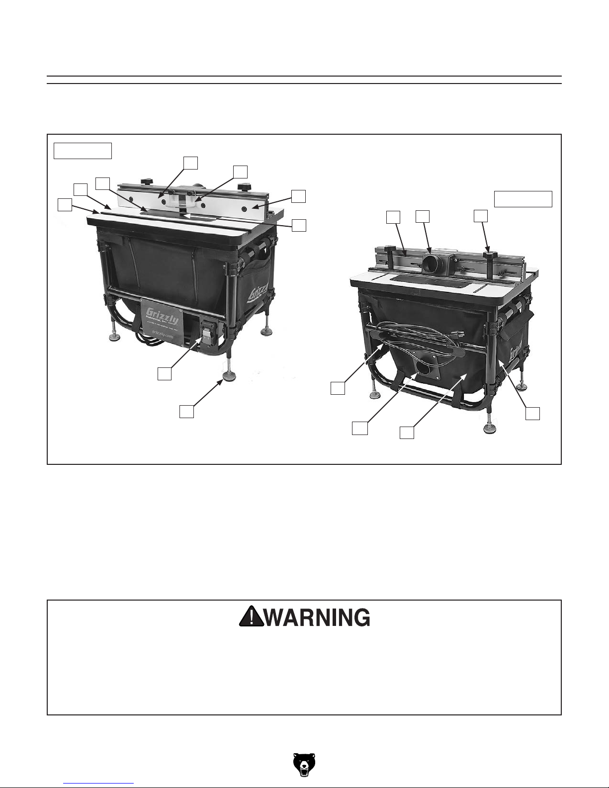
Identification
Become familiar with the names and locations of the controls and features shown below to better understand
the instructions in this manual.
Front View
D
C
B
A
E
F
G
H
I
Rear View
J
P
N
O
A. T-Slot Track 3⁄4"
B. Table
C. Mounting Plate
D. Outfeed Fence
E. Router Bit Guard
F. Infeed Fence
G. Table Insert
H. Fence Support
M
I. Fence Dust Port 21⁄2 "
J. Fence Lock
K. Side Storage Pocket (1 of 2)
L. Dust Collection Bag
M. Bag Dust Port 2
N. Power Cord
O. Adjustable Feet (1 of 4)
P. ON/OFF Paddle Switch w/Disabling Key
L
1
⁄2 "
For Your Own Safety Read Instruction Manual Before Operating Router Table
a) Wear eye protection.
b) Always keep router bit guard in place and in proper operating condition.
c) Feed workpiece AGAINST rotation of router bit.
d) Keep fingers away from revolving bit–use fixtures when necessary.
e) Do not use awkward hand positions.
K
Model T28048 (Mfd. Since 06/17)
-3-
Controls &
To reduce your risk of
serious injury, read this
entire manual BEFORE
F. Mounting Plate. Plate used to attach router
to table.
Components
using machine.
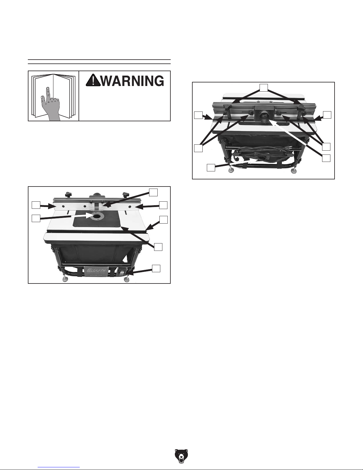
Refer to the following figures and descriptions to
become familiar with the basic controls and components of this machine. Understanding these
items and how they work will help you understand
the rest of the manual and minimize your risk of
injury when operating this machine.
C
B
A
Figure 1. Router table controls (front).
D
E
F
G
G. ON/OFF Paddle Switch w/Disabling Key.
Turns router ON and OFF. Remove key to
disable switch.
H
I
J
K
Figure 2. Router table controls (rear).
H. Fence Board Locks. Tighten and loosen
fence boards for side-to-side adjustment.
I. Fence Board Shims. Provide
offsets to fence boards for edge jointing
operations.
J. Fence Locks. Tighten and loosen fence
assembly for front-to-rear adjustment.
1
K. Dust Ports. Two 2
the user's dust-collection system.
⁄2" dust ports connect to
1
⁄32" and 1⁄16"
I
J
K
A. Table Insert. Provides additional workpiece
control and safety near the router bit during
operations.
B. Outfeed Fence Board. Provides workpiece
support during router operations.
C. Router Bit Guard. Provides workpiece vis-
ibility and safety during operations.
D. Infeed Fence Board. Provides workpiece
support during router operations.
E. T-Slot. Provides secure attachment point
for router table accessories, such as miter
gauges, jigs, and feather boards.
-4-
Model T28048 (Mfd. Since 06/17)

Customer Service #: (570) 546-9663 · To Order Call: (800) 523-4777 · Fax #: (800) 438-5901
2, 1-3/8, 1/2 in.
MODEL T28048
BENCHTOP ROUTER TABLE
Product Dimensions:
Weight ............................................................................................................................................................................. 30 lbs.
Width (side-to-side) x Depth (front-to-back) x Height .................................................................................24 x 16 x 23-1/2 in.
Footprint (Length/Width) ............................................................................................................................................22 x 15 in.
Shipping Dimensions:
Type ................................................................................................................................................................... Cardboard Box
Content .......................................................................................................................................................................... Machine
Weight .............................................................................................................................................................................. 36 lbs.
Length x Width x Height ...............................................................................................................................25-1/2 x 18 x 10 in.
Must Ship Upright .................................................................................................................................................................. No
Electrical:
Connection Type ..................................................................................................................................................... Cord & Plug
Power Cord Included ............................................................................................................................................................Yes
Power Cord Length .............................................................................................................................................................10 ft.
Power Cord Gauge .......................................................................................................................................................14 AWG
Plug Included ........................................................................................................................................................................Yes
Included Plug Type ..................................................................................................................................................NEMA 5-15
Switch Type ............................................................................................................ ON/OFF Paddle Switch w/Removable Key
Main Specifications:
Suitable Routers for Mounting .............................................................................................3/4–2-1/2 HP Non-Plunge Routers
Table Size ................................................................................................................................................23-1/2 x 15-3/4
Number of Table T-Slots ...........................................................................................................................................................1
Table T-Slot Size ..............................................................................................................................................................3/4 in.
Plate Size ...............................................................................................................................................11-3/4 x 9-1/4
Maximum Plate Opening Size ....................................................................................................................................... 3-3/4
Plate Insert Openings ........................................................................................................................................
Fence Size ...........................................................................................................................................23-5/8 x 3-1/2 x 3-1/4
Fence Board Size .................................................................................................................................. 11-1/4 x 3/4 x 2-1/2 in.
Fence Board Offsets ..............................................................................................................................................1/32, 1/16 in.
Dust Port Inside Diameter Size ....................................................................................................................................2-1/4 in.
Dust Port Outside Diameter Size ..................................................................................................................................2-1/2 in.
Construction:
Table ............................................................................................................................................Edgebanded Laminated MDF
Fence Assembly ....................................................................................... Anodized Extruded-Aluminum and Laminated MDF
Router Guard .............................................................................................................................................Clear Polycarbonate
T-Slot ........................................................................................................................................... Anodized Extruded Aluminum
Stand ....................................................................................................................................................... 1-1/4 in. Tubular Steel
Dust Collection Bag and Side Pockets ...........................................................................................................................Canvas
Other Specifications:
Country of Origin ............................................................................................................................................................... China
Warranty ........................................................................................................................................................................... 1 Year
Approximate Assembly & Setup Time ...................................................................................................................... 30 Minutes
ISO 9000 Factory ..................................................................................................................................................................Yes
x 1 in.
x 3/8 in.
in.
in.
Model T28048 (Mfd. Since 06/17)
-5-

Features:
Universal Aluminum Mounting Plate
Clear Polycarbonate Router Guard
Hand-Adjustable Fence Assembly and Fence Boards
Anodized Extruded-Aluminum Fence Board Shims
Enclosed Canvas Dust Collection Bag
Canvas Side Pockets w/Tool Pouches
Shop Vacuum Compatible Dust Ports
Adjustable Feet
Accessories:
Plate Insert w/2" Diameter Bit Hole
Plate Insert w/1-3/8" Diameter Bit Hole
Plate Insert w/1/2" Diameter Bit Hole
Plate Insert Wrench
Starting Pin
Hex Wrench 3mm
Hex Wrench 4mm
Hex Wrench 5mm
-6-
Model T28048 (Mfd. Since 06/17)
SECTION 1: SAFETY
For Your Own Safety, Read Instruction
Manual Before Operating This Machine
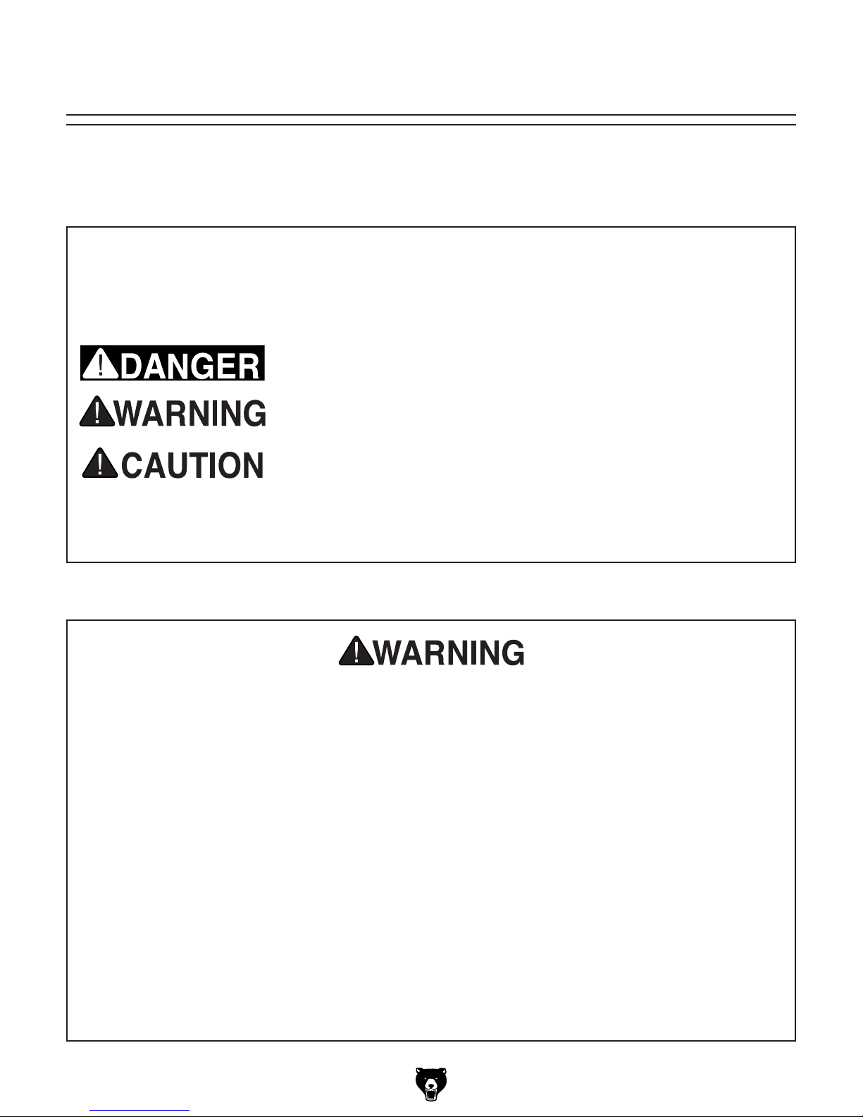
The purpose of safety symbols is to attract your attention to possible hazardous conditions.
This manual uses a series of symbols and signal words intended to convey the level of importance of the safety messages. The progression of symbols is described below. Remember that
safety messages by themselves do not eliminate danger and are not a substitute for proper
accident prevention measures. Always use common sense and good judgment.
Indicates an imminently hazardous situation which, if not avoided,
WILL result in death or serious injury.
Indicates a potentially hazardous situation which, if not avoided,
COULD result in death or serious injury.
Indicates a potentially hazardous situation which, if not avoided,
MAY result in minor or moderate injury. It may also be used to alert
against unsafe practices.
This symbol is used to alert the user to useful information about
NOTICE
proper operation of the machine.
Safety Instructions for Machinery
OWNER’S MANUAL. Read and understand this
owner’s manual BEFORE using machine.
TRAINED OPERATORS ONLY. Untrained operators have a higher risk of being hurt or killed.
Only allow trained/supervised people to use this
machine. When machine is not being used, disconnect power, remove switch keys, or lock-out
machine to prevent unauthorized use—especially
around children. Make your workshop kid proof!
DANGEROUS ENVIRONMENTS. Do not use
machinery in areas that are wet, cluttered, or have
poor lighting. Operating machinery in these areas
greatly increases the risk of accidents and injury.
MENTAL ALERTNESS REQUIRED. Full mental
alertness is required for safe operation of machinery. Never operate under the influence of drugs or
alcohol, when tired, or when distracted.
ELECTRICAL EQUIPMENT INJURY RISKS. You
can be shocked, burned, or killed by touching live
electrical components or improperly grounded
machinery. To reduce this risk, only allow qualified
service personnel to do electrical installation or
repair work, and always disconnect power before
accessing or exposing electrical equipment.
DISCONNECT POWER FIRST.
nect machine from power supply BEFORE making
adjustments, changing tooling, or servicing machine.
This prevents an injury risk from unintended startup
or contact with live electrical components.
EYE PROTECTION. Always wear ANSI-approved
safety glasses or a face shield when operating or
observing machinery to reduce the risk of eye
injury or blindness from flying particles. Everyday
eyeglasses are NOT approved safety glasses.
Always discon-
Model T28048 (Mfd. Since 06/17)
-7-

WEARING PROPER APPAREL. Do not wear
clothing, apparel or jewelry that can become
entangled in moving parts. Always tie back or
cover long hair. Wear non-slip footwear to reduce
risk of slipping and losing control or accidentally
contacting cutting tool or moving parts.
HAZARDOUS DUST. Dust created by machinery
operations may cause cancer, birth defects, or
long-term respiratory damage. Be aware of dust
hazards associated with each workpiece material. Always wear a NIOSH-approved respirator to
reduce your risk.
HEARING PROTECTION. Always wear hearing protection when operating or observing loud
machinery. Extended exposure to this noise
without hearing protection can cause permanent
hearing loss.
REMOVE ADJUSTING TOOLS. Tools left on
machinery can become dangerous projectiles
upon startup. Never leave chuck keys, wrenches,
or any other tools on machine. Always verify
removal before starting!
USE CORRECT TOOL FOR THE JOB. Only use
this tool for its intended purpose—do not force
it or an attachment to do a job for which it was
not designed. Never make unapproved modifications—modifying tool or using it differently than
intended may result in malfunction or mechanical
failure that can lead to personal injury or death!
AWKWARD POSITIONS. Keep proper footing
and balance at all times when operating machine.
Do not overreach! Avoid awkward hand positions
that make workpiece control difficult or increase
the risk of accidental injury.
CHILDREN & BYSTANDERS. Keep children and
bystanders at a safe distance from the work area.
Stop using machine if they become a distraction.
GUARDS & COVERS. Guards and covers reduce
accidental contact with moving parts or flying
debris. Make sure they are properly installed,
undamaged, and working correctly BEFORE
operating machine.
FORCING MACHINERY. Do not force machine.
It will do the job safer and better at the rate for
which it was designed.
NEVER STAND ON MACHINE. Serious injury
may occur if machine is tipped or if the cutting
tool is unintentionally contacted.
STABLE MACHINE. Unexpected movement during operation greatly increases risk of injury or
loss of control. Before starting, verify machine is
stable and mobile base (if used) is locked.
USE RECOMMENDED ACCESSORIES. Consult
this owner’s manual or the manufacturer for recommended accessories. Using improper accessories will increase the risk of serious injury.
UNATTENDED OPERATION. To reduce the
risk of accidental injury, turn machine OFF and
ensure all moving parts completely stop before
walking away. Never leave machine running
while unattended.
MAINTAIN WITH CARE. Follow all maintenance
instructions and lubrication schedules to keep
machine in good working condition. A machine
that is improperly maintained could malfunction,
leading to serious personal injury or death.
DAMAGED PARTS. Regularly inspect machine
for damaged, loose, or mis-adjusted parts—or
any condition that could affect safe operation.
Immediately repair/replace BEFORE operating
machine. For your own safety, DO NOT operate
machine with damaged parts!
MAINTAIN POWER CORDS. When disconnecting cord-connected machines from power, grab
and pull the plug—NOT the cord. Pulling the cord
may damage the wires inside. Do not handle
cord/plug with wet hands. Avoid cord damage by
keeping it away from heated surfaces, high traffic
areas, harsh chemicals, and wet/damp locations.
EXPERIENCING DIFFICULTIES. If at any time
you experience difficulties performing the intended operation, stop using the machine! Contact our
Technical Support at (570) 546-9663.
-8-
Model T28048 (Mfd. Since 06/17)

Additional Safety for Router Tables
Serious cuts, amputation, entanglement, or death can occur from contact with rotating bit.
Bits or other parts improperly secured can fly off and strike nearby operators with great force.
Flying debris can cause eye injuries or blindness. To minimize risk of getting hurt or killed,
anyone operating shaper MUST completely heed hazards and warnings below.
AVOIDING AMPUTATION. To avoid making con-
tact with spinning router bit, never place hands
directly over or in front of bit. As one hand
approaches bit, move it away and over to other
side. Always keep hands at least 6" away from
spinning bit.
SECURING LEVERS AND KNOBS. Never operate router table without first making sure all lock
levers and knobs are tight, and all fence hardware
and guide rails are secure. Otherwise, workpiece
can slip out of alignment while cutting and cause
injury from kickback.
DO NOT FORCE WORKPIECE. Never force
materials past router. Let router bit do work.
Excessive force is likely to result in poor cutting
results and will cause kickback conditions that
could cause serious personal injury.
BLIND CUTTING. Keep router bit on underside
of workpiece when making blind cuts. This will
decrease risk of accidental contact with rotating
bit.
ROUTER BIT ROTATION. Always feed workpiece against rotation direction of bit. Otherwise,
workpiece could be aggressively pulled from your
hands, drawing them into spinning bit.
ROUTER BIT HEIGHT. Keep any unused portion
of bit below the table surface to minimize risk of
your hand contacting rotating bit.
APPROPRIATE WORKPIECES. Danger of kickback and injury is increased when workpiece
has knots, holes, or foreign objects in it. Warped
stock should be flattened with a jointer before you
shape it with router.
TESTING ROTATION. With router disconnected
from power, rotate router spindle to test any new
setup to ensure proper bit clearance before starting router.
CUTTING SUPPORT. NEVER cut workpiece
without using a fence, jig, or miter gauge as a
support guide. Otherwise, workpiece could be
aggressively pulled from your hands, drawing
them into spinning bit.
WORKPIECE SIZING. NEVER use workpiece
shorter than 6" without special fixtures or jigs.
Otherwise, workpiece can become trapped
between fence and router bit, which could draw
your hands into spinning bit.
USING SAFETY GUARDS. To prevent amputation or other injuries, always use a guard.
Fabricate additional guards or jigs for special
circumstances. Use an overhead guard if fence
is removed.
TRIPPING HAZARD. To prevent tripping over
power cord of router when not in use, always disconnect it and safely store it out of way.
Model T28048 (Mfd. Since 06/17)
-9-

SECTION 2: ELECTRICAL
Before installing the machine, consider the availability and proximity of the required power supply
circuit. If an existing circuit does not meet the
requirements for this machine, a new circuit must
be installed. To minimize the risk of electrocution,
fire, or equipment damage, installation work and
electrical wiring must be done by an electrician or
qualified service personnel in accordance with all
applicable codes and standards.
or equipment damage
not properly grounded
For your own safety and protection of
Note: Circuit requirements in this manual apply to
a dedicated circuit—where only one machine will
be running on the circuit at a time. If machine will
be connected to a shared circuit where multiple
machines may be running at the same time, consult an electrician or qualified service personnel to
ensure circuit is properly sized for safe operation.
A power supply circuit includes all electrical
equipment between the breaker box or fuse panel
in the building and the machine. The power supply circuit used for this machine must be sized to
safely handle the full-load current drawn from the
machine for an extended period of time. (If this
machine is connected to a circuit protected by
fuses, use a time delay fuse marked D.)
This machine is prewired to operate on a power
supply circuit that has a verified ground and meets
the following requirements:
Availability
110V Circuit Requirements
Nominal Voltage .................... 110V, 115 V, 120V
Cycle .......................................................... 60 Hz
Phase ........................................... Single-Phase
Power Supply Circuit ......................... 15 Amps
Electrocution, fire, shock,
may occur if machine is
and connected to power
supply.
Serious injury could occur if you connect
machine to power before completing setup
process. DO NOT connect to power until
instructed later in this manual.
-10 -
property, consult an electrician if you are
unsure about wiring practices or electrical
codes in your area.
Model T28048 (Mfd. Since 06/17)
Improper connection of the equipment-grounding
wire can result in a risk of electric shock. The
wire with green insulation (with or without yellow
stripes) is the equipment-grounding wire. If repair
or replacement of the power cord or plug is necessary, do not connect the equipment-grounding
wire to a live (current carrying) terminal.
Check with a qualified electrician or service personnel if you do not understand these grounding
requirements, or if you are in doubt about whether
the tool is properly grounded. If you ever notice
that a cord or plug is damaged or worn, disconnect it from power, and immediately replace it with
a new one.
We do not recommend using an extension cord
with this machine.
cord, only use it if absolutely necessary and only
on a temporary basis.
Extension cords cause voltage drop, which can
damage electrical components and shorten motor
life. Voltage drop increases as the extension cord
size gets longer and the gauge size gets smaller
(higher gauge numbers indicate smaller sizes).
Any extension cord used with this machine must
be in good condition and contain a ground wire
and matching plug/receptacle. Additionally, it must
meet the following size requirements:
Grounding & Plug Requirements
it will not fit the outlet, have a qualified
electrician install the proper outlet with a
This machine MUST be grounded. In the event
of certain malfunctions or breakdowns, grounding
reduces the risk of electric shock by providing a
path of least resistance for electric current.
This machine is equipped with a power cord that
has an equipment-grounding wire and a grounding
plug. Only insert plug into a matching receptacle
(outlet) that is properly installed and grounded in
accordance with all local codes and ordinances.
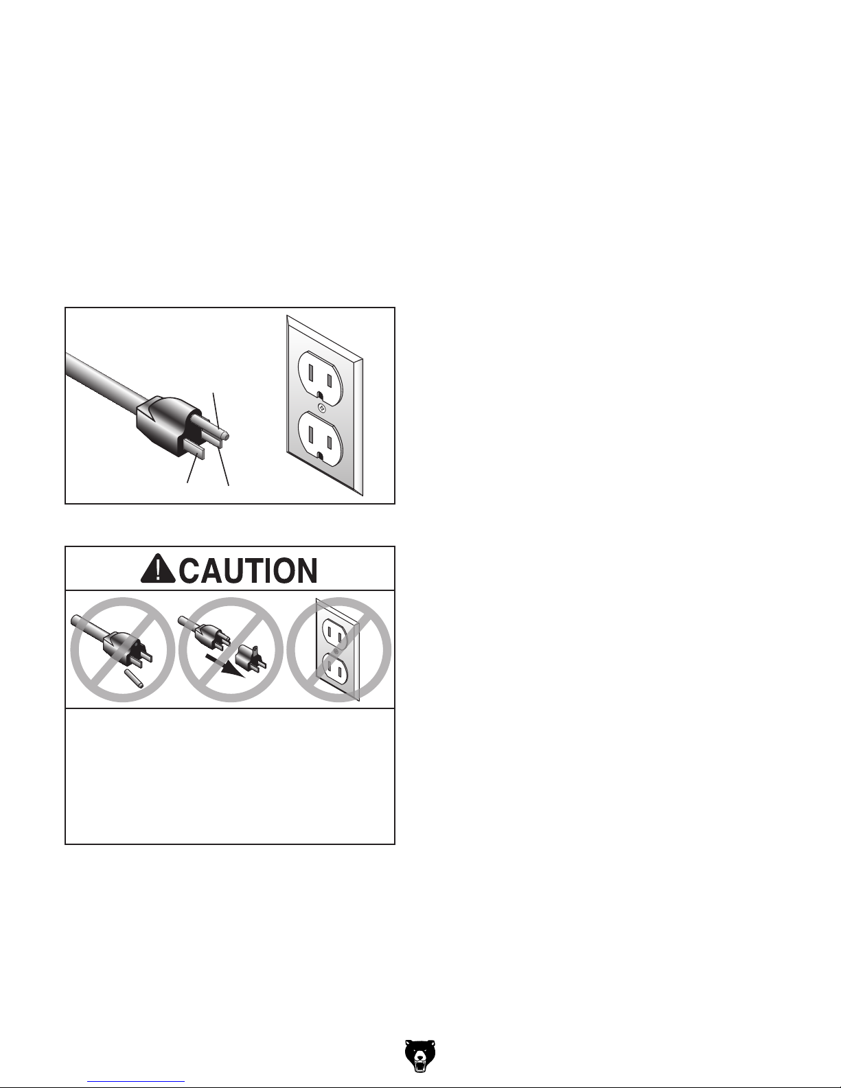
DO NOT modify the provided plug!
GROUNDED
5-15 RECEPTACLE
Grounding Prong
5-15 PLUG
Neutral Hot
Figure 3. Typical 5-15 plug and receptacle.
Connecting to ON/OFF Paddle Switch
The Model T28048 includes an ON/OFF paddle
switch with disabling key. Two power cords are
connected to the switch. The shorter power cord
has a 5-15 receptacle and connects to the router
power cord. The longer power cord has a 5-15
plug and connects to a 110V power supply circuit.
(See Connecting Power Cords on Page 23
detailed information about connecting a router to
the Model T28048.)
SHOCK HAZARD!
Two-prong outlets do not meet the grounding
requirements for this machine. Do not modify
or use an adapter on the plug provided—if
verified ground.
Model T28048 (Mfd. Since 06/17)
Extension Cords
If you must use an extension
Minimum Gauge Size ...........................14 AWG
Maximum Length (Shorter is Better).......50 ft.
-11-
SECTION 3: SETUP
This machine was carefully packaged for safe
transport. When unpacking, separate all enclosed
items from packaging materials and inspect them
for shipping damage.
,
please
IMPORTANT:
you are completely satisfied with the machine and
have resolved any issues between Grizzly or the
shipping agent. You MUST have the original pack-
aging to file a freight claim. It is also extremely
helpful if you need to return your machine later.
Keep children and pets away
from plastic bags or packing
materials shipped with this
This machine presents
serious injury hazards
to untrained users. Read
through this entire manual to become familiar with
the controls and operations before starting the
machine!
Wear safety glasses during
the entire setup process!
Unpacking
Needed for Setup
The following items are needed, but not included,
for the setup/assembly of this machine.
Description Qty
• Screwdriver Phillips #2 ............................... 1
• Open-End Wrench 10mm ........................... 1
• Open-End Wrench 14mm ........................... 1
• Drill Press or Hand Drill w/Guide ................ 1
• Drill Bits (Variable) ................................1 Ea.
• Straightedge 24" ......................................... 1
• Level ........................................................... 1
• Center Punch ............................................. 1
• Erasable Marker ......................................... 1
• Dust-Collection System .............................. 1
• Dust Hose 2
• Hose Clamps 2
1
⁄2 " OD ................................ 1–2
1
⁄2 " .................................. 1 – 2
If items are damaged
call us immediately at (570) 546-9663.
Save all packaging materials until
SUFFOCATION HAZARD!
-12-
machine. Discard immediately.
Model T28048 (Mfd. Since 06/17)
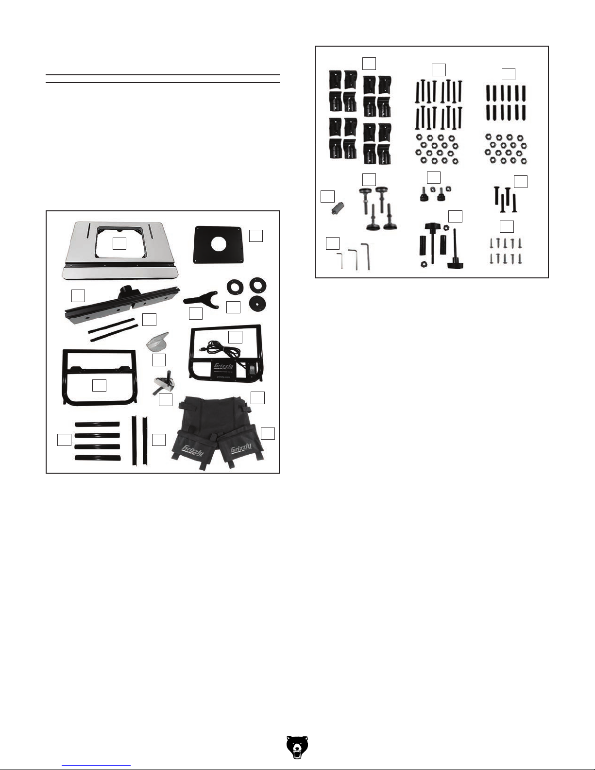
Inventory
The following is a list of items shipped with your
machine. Before beginning setup, lay these items
out and inventory them.
If any non-proprietary parts are missing (e.g. a
nut or a washer), we will gladly replace them; or
for the sake of expediency, replacements can be
obtained at your local hardware store.
O
P
Q
A
C
D
H
G
N
J
Figure 4. T28048 inventory.
Box Contents (Figure 4) Qty
A. Table ........................................................... 1
B. Mounting Plate............................................ 1
C. Fence Assembly ......................................... 1
D. Fence Board Spacers ................................ 2
E. Table Insert Wrench ................................... 1
F. Table Inserts:
G. Front Frame ................................................ 1
H. Router Bit Guard ........................................ 1
I. Rear Frame ................................................ 1
J. Frame Connector Tubes ............................. 4
K. Side Frame Support Brackets .................... 2
L. Dust Collection Bag .................................... 1
M. Side Pockets .............................................. 2
N. Miter Gauge ................................................ 1
K
1
⁄2 ", 13⁄8", 2" .....................1 Ea.
E
S
R
B
P
F
I
L
M
V
Figure 5. T28048 hardware inventory.
Hardware (Figure 5) Qty
O. Tube Clamps
— Inner Tube Clamps ................................. 8
— Outer Tube Clamps ................................. 8
P. Tube Clamp Hardware
—Flat Head Cap Screws M6-1 x 50 ........ 16
— Hex Nuts M6-1 ...................................... 16
Q. Mounting Plate Leveling Hardware
— Set Screws M6-1 x 30 .......................... 12
— Hex Nuts M6-1 ...................................... 12
R. Starter Pin M6-1 x 25 ................................. 1
S. Router Table Feet ....................................... 4
T. Router Bit Guard Hardware
— Thumb Screws M6-1 x 15 ....................... 2
—Square Nuts M6-1 ................................... 2
U. Mounting Plate Hardware
— Flat Head Cap Screws M6-1 x 35 ........... 4
V. Hex Wrenches 3, 4, 5mm .....................1 Ea.
W. Fence Hardware
— Knob Bolts M8-1.25 x 90 ........................ 2
— Plastic Spacers ....................................... 2
—Extra-Wide Hex Nuts M8-1.25 ................ 2
X. Frame Hardware
— Tap Screws M5 x 20 ............................. 10
T
W
U
X
Model T28048 (Mfd. Since 06/17)
-13-
 Loading...