

Page 1
MODEL T27978
50-TON HYDRAULIC PRESS
INSTRUCTIONS
For questions or help with this product contact Tech Support at (570) 546-9663 or techsupport@grizzly.com
EYE INJURY HAZARD!
Always wear safety glasses
during use to prevent
serious personal injury.
INJURY HAZARD!
When servicing, always disconnect tool from air to prevent unexpected operation.
125 PSI
MAX AIR PRESSURE!
Exceeding this PSI may
result in injury/tool damage.
Workpieces positioned off-center below
hydraulic ram can be ejected unexpectedly
from force being applied unevenly, striking
operator or bystanders with great force.
Always ensure workpiece is positioned
so force is evenly distributed. STOP and
release compression if workpiece shifts
during pressing.
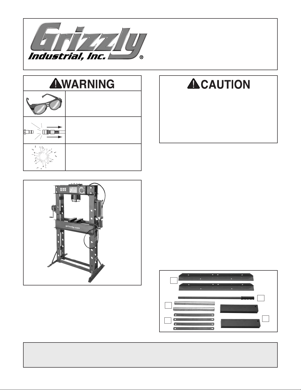
Inventory
Open shipping crate and remove inventory items
included inside (see Figure 2).
Description (Figure 2) Qty
A. Hydraulic Press Assembly (not shown) ...... 1
B. Base Supports ............................................ 2
C. Pump Handle .............................................. 1
D. Support Rods ............................................. 2
E. Press Blocks ............................................... 2
F. Angle Braces .............................................. 4
G. Hardware Bag (not shown)
• Hex Bolts M10-1.5 x 25 ....................... 12
• Cap Screws M8-1.25 x 30 .................... 4
• Lock Washers 8mm ............................ 12
• Flat Washers 8mm ............................. 12
• Hex Nuts M10-1.5 ............................... 12
Figure 1. Model T27978.
Needed For Setup
Description Qty
Additional People ................................................. 2
Safety Glasses .............................................. 1 Ea.
Open-End Wrenches 13, 16, 18, 19mm ...... 1 Ea.
ISO VG32 Hydraulic Oil ........................2.5 Quarts
COPYRIGHT © JUNE, 2017 BY GRIZZLY INDUSTRIAL, INC. REVISED DECEMBER, 2018 (JL)
NO PORTION OF THIS MANUAL MAY BE REPRODUCED IN ANY SHAPE
OR FORM WITHOUT THE WRITTEN APPROVAL OF GRIZZLY INDUSTRIAL, INC.
#JH18676 PRINTED IN CHINA
B
C
D
F
Figure 2. Inventory items.
E
Page 2
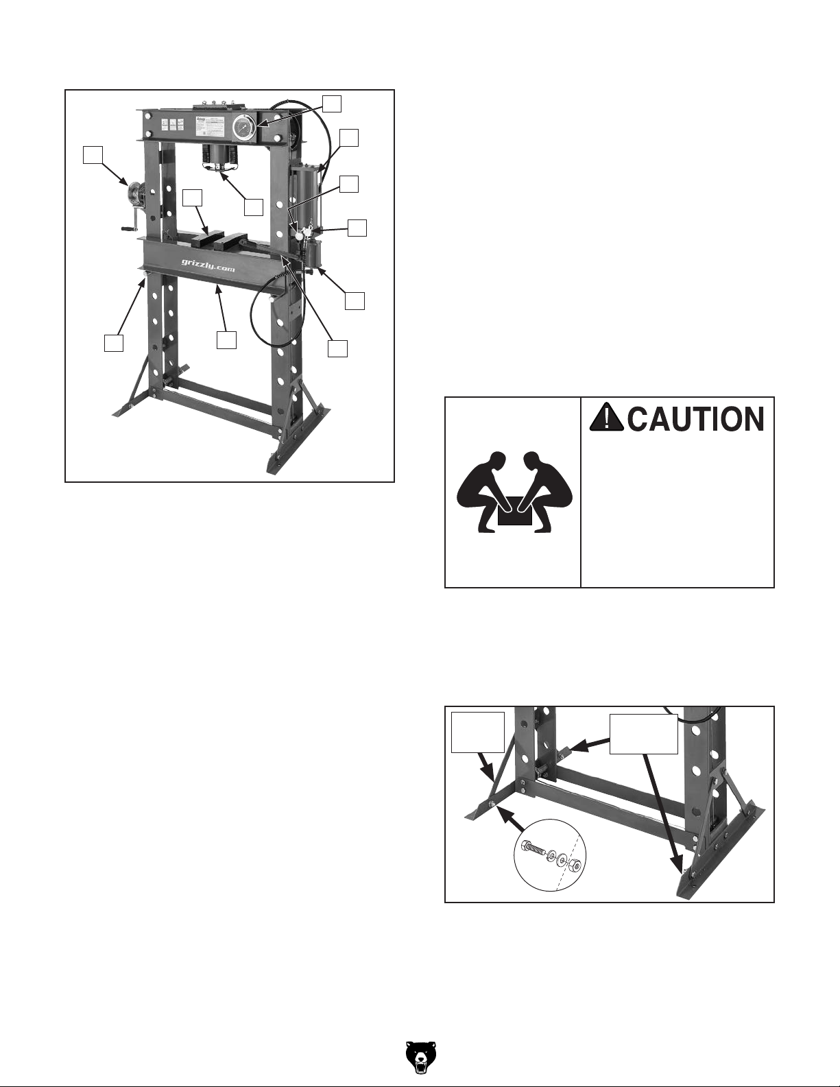
Identification
A
I. Pump Handle. Manually lowers ram into
workpiece in small increments.
D
J. Press Bed. Supports workpiece during
E
pressing operation. Bed raises and lowers
using winch.
F
B
K
Figure 3. Machine components.
A. Winch. Raises and lowers press bed to
adjust bed height.
B. Table Plates. Support workpiece during
bending operation.
C. Hydraulic Ram. Applies pressure directly
to workpiece. Hydraulic ram operates using
both incoming air line for rapid downward
movement and manual pump handle for
slower downward ram movement.
D. Pressure Gauge. Shows pounds of force
being applied to workpiece.
C
G
H
J
I
K. Support Rods. Support press bed at prede-
termined heights of holes in machine frame.
Assembly
1. With the help of two assistants, remove
press from shipping crate, hold upright, and
attach both base supports (see Figure 4)
using (4) M10-1.5 x 25 hex bolts, 10mm flat
washers, 10mm lock washers, and M10-1.5
hex nuts.
This machine and its
components are very
heavy. Reduce risk of
strain or lifting injury
by getting lifting help or
using power lifting equipment such as a forklift to
move heavy items.
2. Attach angle braces to each base support
using (8) M10-1.5 x 25 hex bolts, 10mm flat
washers, 10mm lock washers, and M10-1.5
hex nuts, as shown in Figure 4.
Angle
Brace
Base
Supports
E. Hydraulic Fluid Reservoir. Holds hydraulic
fluid for operation of hydraulic ram.
F. Tank Relief Valve. Releases pressure from
hydraulic ram to release workpiece.
G. Air Cylinder Control. Valve controls amount
of air released from air line cylinder to
hydraulic ram.
H. Air Line Cylinder. Provides pressure to
lower hydraulic ram. Maximum incoming air
pressure is 125 PSI.
-2-
Figure 4. Supports and angle braces installed.
T27978 50-Ton Hydraulic Press (Mfd. 12/16)
Page 3
3. Attach hydraulic reservoir assembly to out-
Anchoring machinery to the floor prevents tipping
or shifting and reduces vibration that may occur
during operation, resulting in a machine that runs
slightly quieter and feels more solid.
If the machine will be installed in a commercial or
workplace setting, local codes may require that it
be anchored to the floor.
If not required by any local codes, fastening the
machine to the floor is an optional step. If you
choose not to do this with your machine, we recommend placing it on machine mounts, as these
provide an easy method for leveling and they have
vibration-absorbing pads.
Lag shield anchors with lag screws (see below)
are a popular way to anchor machinery to a concrete floor, because the anchors sit flush with the
floor surface, making it easy to unbolt and move
the machine later, if needed. However, anytime
local codes apply, you MUST follow the anchoring
methodology specified by the code.
side of press frame (see Figure 5) by threading (4) M10-1.5 x 30 hex bolts, 10mm flat
washers, and 10mm lock washers through
frame mounting bracket into threaded holes
of hydraulic assembly.
Hydraulic
Assembly
Anchoring to Floor
Number of Mounting Holes ............................ 4
Diameter of Mounting Hardware .................
3
⁄8"
Frame
Mounting
Bracket
Figure 5. Mounting hydraulic assembly.
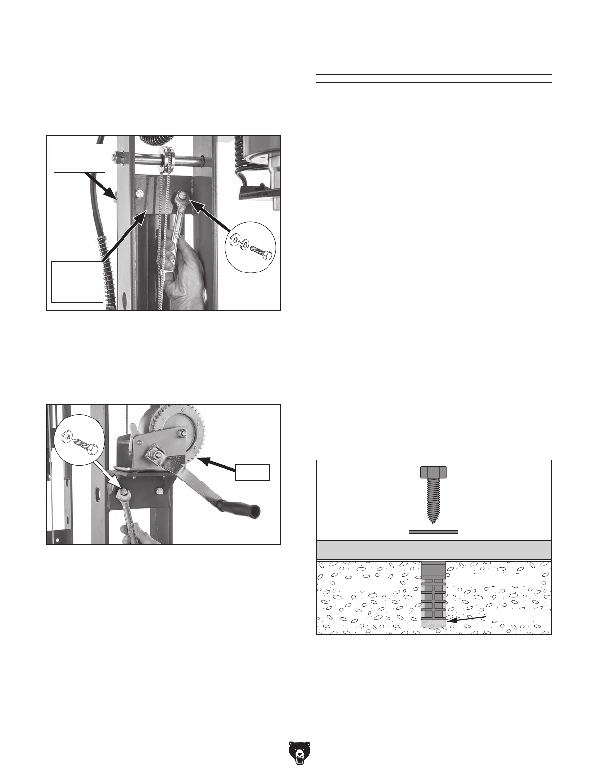
4. Attach winch to outside of press frame, as
shown in Figure 6, using (2) M10-1.5 x 25
hex bolts, 10mm flat washers, and M10-1.5
hex nuts.
x 2
Figure 6. Mounting winch to press frame.
x 4
Winch
Anchoring to Concrete Floors
Lag Screw
Flat Washer
Machine Base
Concrete
Lag Shield Anchor
Drilled Hole
T27978 50-Ton Hydraulic Press (Mfd. 12/16)
Figure 7. Popular method for anchoring
machinery to a concrete floor.
-3-
Page 4

Operating Press
1. Rotate tank relief valve (see Figure 8) fully
clockwise to close it. Ensure top relief valve
is open 1–2 turns.
Tank
Relief
Valve
Top
Relief
Valve
Figure 8. Hydraulic system relief valve locations.
Support Rod
(1 of 2)
Figure 10. Support rod placement.
3. Connect air valve to incoming air compressor
line. Confirm incoming air pressure is 110–
125 PSI.
Incoming
Air Line
2. Engage latch on winch (see Figure 9), and
raise press bed to desired height, insert
support rods (see Figure 10) into holes in
machine frame closest to bed, then lower bed
onto support rods.
ALWAYS ensure winch latch is engaged
when raising/lowering press bed! Engaging
latch prevents bed from accidentally
dropping if winch handle is released, which
may result in crushing injury.
Disengaged
Engaged
Air
Valve
Figure 11. Air valve movement.
4. Place table plates on press bed (see Figure
12), and place workpiece on table plates.
Press
Bed
Ram
Table
Plates
Figure 12. Table plates positioned on press bed
beneath ram.
-4-
Latch
Figure 9. Winch latch positions.
T27978 50-Ton Hydraulic Press (Mfd. 12/16)
Page 5

Workpieces positioned off-center below
hydraulic ram can be ejected unexpectedly
from force being applied unevenly, striking
operator or bystanders with great force.
Always ensure workpiece is positioned
so force is evenly distributed. STOP and
release compression if workpiece shifts
during pressing.
5. Lower ram by pressing and holding air valve
tab (see Figure 13). Ram should lower
smoothly.
7. Rotate tank relief valve (see Figure 15) coun-
terclockwise to release pressure on ram, then
remove workpiece.
Tank
Relief
Valve
Figure 15. Rotating tank relief valve.
Air
Line
Figure 13. Air valve components/controls.
6. For precise application of ram force on work-
piece, pump handle to increase pressure
incrementally. Refer to pressure gauge for
actual workpiece pressure (see Figure 14).
Air
Valve
Tab
Air
Valve
Maintenance
The T27978 50-Ton Press features a fully-sealed
hydraulic unit and air cylinder. Periodically check
press for loose mounting bolts or any unsafe conditions. Thoroughly clean press components on
an as-needed basis for best operation.
To clean/maintain press:
1. Wipe all dirt and dust off press components.
2. Apply light oil to surface of ram.
3. Check hydraulic ram and press bed sup-
port rods for cracks or damage. Replace if
necessary.
Pressure Gauge
Figure 14. Pump handle and pressure gauge.
T27978 50-Ton Hydraulic Press (Mfd. 12/16)
-5-
Page 6

T27978 Parts Breakdown
Please Note: We do our best to stock replacement parts whenever possible, but we cannot guarantee that all parts shown here
are available for purchase. Call (800) 523 - 4777 or visit our online parts store at www.grizzly.com to check for availability.
29
37
41
40
26
30
38
11
34
32
52
35
50
33
27
8
13
11
61
2
1
10
51
16
60
6
5
55
22
36
23
15
54
45
46
51
37
13
36
16
38
3
4
25
1
49
40
24
7
42
53
59
43
11
18
48
57
58
47
56
44
19
9
21
62
12
63
10
36
17
64
65
PARTS STORE
14
37
38
20
39
12
66
BUY PARTS ONLINE!
Scan QR code with your
digital device or visit
www.grizzly.com/parts
to purchase replacement
parts or check pricing and
availability.
-6-
T27978 50-Ton Hydraulic Press (Mfd. 12/16)
Page 7

Main Parts List
REF PART # DESCRIPTION REF PART # DESCRIPTION
1 PT27978001 HEX BOLT M22-2.5 X 50 35 PT27978035 CABLE BLOCK
2 PT27978002 CROSS BEAM 36 PT27978036 HEX NUT M10-1.5
3 PT27978003 HEX NUT M14-2 37 PT27978037 LOCK WASHER 10MM
4 PT27978004 LOCK WASHER 14MM 38 PT27978038 FLAT WASHER 10MM
5 PT27978005 FLAT WASHER 22MM 39 PT27978039 CABLE PULLEY (LOWER)
6 PT27978006 HEX NUT M22-2.5 40 PT27978040 EXT RETAINING RING 20MM
7 PT27978007 COLUMN 41 PT27978041 HEX NUT M14-2
8 PT27978008 PRESS BED SUPPORT ROD 42 PT27978042 KNURLED KNOB M10-1.5 X 38L X 40D
9 PT27978009 ANGLE SUPPORT BAR 43 PT27978043 AIR HOSE 1/4" ID 300-PSI 48"L
10 PT27978010 FLAT WASHER 12MM 44 PT27978044 PNEUMATIC HAND VALVE 1/4" NPT
11 PT27978011 HEX BOLT M10-1.5 X 25 45 PT27978045 EXTENSION SPRING 1-3/4" X 11" X 1/4"
12 PT27978012 BASE SUPPORT 46 PT27978046 EXTENSION SPRING PLATE
13 PT27978013 HEX NUT M12-1.75 47 PT27978047 OVERFLOW HOSE 5/16" OD X 27"L
14 PT27978014 CROSS SUPPORT 48 PT27978048 HYDRAULIC LINE 1/4" ID 300-PSI 30"L
15 PT27978015 HEX BOLT M8-1.25 X 25 49 PT27978049 HYDRAULIC LINE 1/4" ID 300-PSI 40"L
16 PT27978016 FLAT WASHER 8MM 50 PT27978050 HEX BOLT M8-1.25 X 15
17 PT27978017 HEX BOLT M12-1.75 X 35 51 PT27978051 LOCK WASHER 8MM
18 PT27978018 HYDRAULIC RESERVOIR 52 PT27978052 HEX NUT M8-1.25
19 PT27978019 HANDLE 13/16"D X 26-3/8"L 53 PT27978053 AIR CYCLINDER
20 PT27978020 PRESS BED 54 PT27978054 PRESSURE GAUGE RING
21 PT27978021 PRESS BLOCKS 55 PT27978055 PHLP HD SCR M6-1 X 8
22 PT27978022 PRESSURE GAUGE 56 PT27978056 AIR LINE LOCK FITTING M10-1.5
23 PT27978023 HYDRAULIC RAM 57 PT27978057 90-DEG ELBOW FITTING 3/8" BRASS
24 PT27978024 HEX BOLT M14-2 X 65 58 PT27978058 STRAIGHT FITTING 3/8" BRASS
25 PT27978025 FLAT WASHER 14MM 59 PT27978059 90-DEGREE BLOCK FITTING 1/2"
26 PT27978026 WINCH 1000LB. 60 PT27978060 LOWER PULLEY SHAFT M12-1.75 X 25 SE
27 PT27978027 WINCH BRACKET 61 PT27978061 LOCK WASHER 12MM
29 PT27978029 HEX BOLT M10-1.5 X 35 62 PT27978062 GRIZZLY.COM LABEL
30 PT27978030 STEEL WINCH CABLE 5MM 63 PT27978063 MACHINE ID LABEL
32 PT27978032 PULLEY SHAFT M14-1.75, 20 X 210 DE 64 PT27978064 READ MANUAL LABEL
33 PT27978033 CABLE PULLEY (UPPER) 65 PT27978065 SAFETY GLASSES LABEL
34 PT27978034 FLAT WASHER 14MM 66 PT27978066 AIR DISCONNECT WARNING LABEL
T27978 50-Ton Hydraulic Press (Mfd. 12/16)
-7-
Page 8

 Loading...