

Page 1

MODEL T27713
8" HELICAL CUTTERHEAD
INSTALLATION INSTRUCTIONS
For questions or help with this product contact Tech Support at (570) 546-9663 or techsupport@grizzly.com
Introduction
The Model T27713 indexable-insert helical
cutterhead is designed to replace the straightknife cutterhead on the Model G0656 & G0656P
8" Jointers.
Do NOT modify or alter these cutterheads
to make them fit other makes or models
of jointers for which they aren't designed.
Doing so could result in property damage or
serious personal injury.
The total installation/setup procedure takes
approximately one hour. Read these instructions
thoroughly before beginning. Also, we strongly
recommend replacing the old cutterhead bearings
at the time of installation. The T27713 uses (1)
6203ZZ bearing and (1) 6204ZZ bearing.
Note: Not all pictures in these instructions will
exactly reflect your machine. Some photos are
provided for representation purposes only to help
you better understand the instructions given.
Specifications
Maximum Width of Cut .....................................8"
Cutterhead Diameter ..................................74m m
Number of Indexable Carbide Inserts ............. 40
Indexable Carbide Insert Size ...15 x 15 x 2.5mm
Inventory (Figure 1)
A. Helical Cutterhead 8" ................................. 1
B. Torx Drivers T20 ........................................ 2
C. Torx L-Wrenches T20 ................................ 2
D. Flat Head Torx Screws T20 M6-1 x 15 ...... 3
E. Indexable Carbide Inserts 15 x 15 x 2.5 ..... 5
A
Figure 1.
Helical cutterhead inventory.
B
D
C
E
Recommended Tools
Open-End Wrench 14mm .................................. 1
Open-End Wrench 17mm .................................. 1
Precision Straightedge ...................................... 1
Feeler Gauge Set .............................................. 1
Pair of Heavy Leather Gloves ........................... 1
Safety Glasses (per person) .............................. 1
Pulley Puller ....................................................... 1
Rubber Dead Blow Hammer ............................. 1
Wood Block 12" 4x4 .......................................... 1
Wood Blocks 8" 2x4 .......................................... 2
Shop Rag .......................................................... 1
Degreaser .......................................... As Needed
Flat Piece of Scrap Wood ................................. 1
COPYRIGHT © MAY, 2017 BY GRIZZLY INDUSTRIAL, INC.
WARNING: NO PORTION OF THIS MANUAL MAY BE REPRODUCED IN ANY SHAPE
OR FORM WITHOUT THE WRITTEN APPROVAL OF GRIZZLY INDUSTRIAL, INC.
#MN18965 PRINTED IN CHINA
Page 2

Removing Existing Cutterhead
1. DISCONNECT MACHINE FROM POWER!
2. Remove jointer fence and cutterhead guard.
3. Remove rear cover and belt guard, then
remove V-belt from pulleys.
Jointer knives are extremely sharp. You
must remove the jointer knives, or mount
the knives blade side down to avoid the risk
of serious personal injury during the following steps.
4. Lower both beds to make enough room for
the cutterhead to come out, as shown in
Figure 2.
Note: When lowering, make sure that the
fence support does not come in contact with
the cutterhead pulley.
Figure 2. Example of jointer disassembly Steps
1– 4.
6. Wearing heavy leather gloves, carefully
remove the cutterhead from the casting (see
Figure 4).
Note: Your cutterhead may have paper shims
stuck to the bearing block or where the bearing block rests. These were included at the
factory when they calibrated your cutterhead
to be even with the outfeed table. Your new
cutterhead may or may not need these. If
you see any shims, carefully pull them off
and set them aside for later use—or keep
them with your cutterhead in the event that
you Re-install it later. Also, mark the side of
the cutterhead where they were used, so the
future install will go smoothly.
Bearing
Block
5. Remove nut and lock washer on bearing
block stud, as shown in Figure 3, and repeat
on the other side.
Figure 3. Example of removing nut and lock
washer on bearing block stud.
-2-
Bearing
Block Stud
Figure 4. Example of cutterhead removed.
7. Remove bearing block studs from bearing
blocks.
8. Loosen the two pulley set screws and use
a pulley puller to remove the pulley (see
Page 6). Make sure to remove the key from
the cutterhead shaft keyway and set it aside
so it does not get lost or fall out during the
next step.
T27713 8" Helical Cutterhead
Page 3
Installing Helical Cutterhead
1. Cut a 2x4 into two 8" pieces.
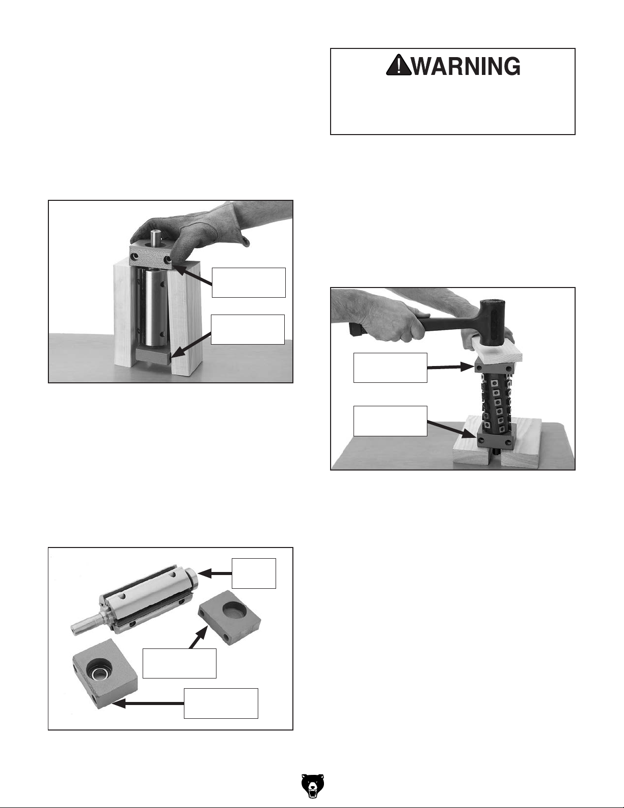
2. Place cutterhead assembly on workbench
or flat surface with pulley side of cutterhead
shaft facing up, then place 2x4 blocks under
rear bearing block, as shown in Figure 5.
Jointer carbide inserts are extremely sharp.
Wear leather gloves to avoid the risk of
serious personal injury during the following
steps.
Tip: Wrapping tape around blocks can help
hold them together during the next step.
Rear Bearing
Block
Front Bearing
Block
Figure 5. Example removing rear bearing block.
3. Tap top of cutterhead shaft with a rubber
dead blow hammer and a 4x4 block. This
should separate cutterhead from rear bearing
block.
5. Install or replace front bearing removed in
Step 4 onto front end (shorter shaft) of your
Model T27713 helical cutterhead, then press
bearing into front bearing block.
6. Stand cutterhead upright between two 8" 2x4
blocks, then use a piece of scrap wood and
a dead blow hammer to seat cutterhead into
bearing blocks, as shown in Figure 7.
Front Bearing
Block
Rear Bearing
Block
4. Repeat Steps 2–3 in a similar manner to
remove cutterhead from front bearing block
and bearing. Figure 6 shows disassembled
components.
Front
Bearing
Front Bearing
Block
Rear Bearing
Block
Figure 6. Example of disassembled cutterhead
assembly.
Figure 7. Example of seating rear bearing block
onto helical cutterhead.
7. Re-install the key onto the keyway, then
press pulley onto new cutterhead shaft.
8. Re-install bearing block studs onto bearing
blocks.
-3-
T27713 8" Helical Cutterhead
Page 4

9. Install cutterhead (see Figure 8) with lock
Outfeed Table
washers and hex nuts previously removed.
Figure 8. Example of helical cutterhead installed.
10. Tighten helical cutterhead in place, and
ensure both pulley set screws are tight.
11. Using straightedge and feeler gauge set,
inspect cutterhead parallelism with outfeed
table as shown in Figure 9. With straightedge
in position, raise or lower outfeed table until
cutterhead body (not the carbide insert) just
touches straightedge.
—If cutterhead is even or within 0.004" with
outfeed table from one side to other, skip
to Step 15.
—If cutterhead is over 0.004" from one side
to other, go to Step 13.
13. Loosen hex nuts securing both bearing block
studs, lift helical cutterhead slightly, then
place a shim beneath bearing block that
needs to be adjusted.
Note: Use shims from your old cutterhead
if available. If not available, newspaper is
approximately 0.003" thick and will work for
shimming (we don't recommend shimming
more than 0.004" on either side, as this may
affect how the bearing block seats in the
casting).
14. Repeat Steps 11–13 and adjust as necessary, then tighten hex nuts on bearing block
studs.
15. Place a straightedge on outfeed table
so it extends over cutterhead, and rotate
cutterhead pulley until one of the carbide
inserts is at top-dead-center (TDC), as shown
in Figures 10 & 11.
Outfeed Table
Figure 9. Checking cutterhead parallelism.
12. Move straightedge to the other side to deter-
-4-
Straightedge
mine if one end of cutterhead body is higher/
lower than the other. (Place feeler gauge
between cutterhead body and straightedge to
determine the height difference.)
Top Dead
Center
Figure 10. Cutterhead insert at top-dead-center.
Straightedge
Figure 11. Setting outfeed table height.
T27713 8" Helical Cutterhead
Page 5

When correctly set, carbide insert will just
touch straightedge when insert is at its highest point of rotation (see Figure 11).
—If your outfeed table is correctly set, no
adjustments are necessary.
—If insert lifts straightedge off table or if table
is below straightedge, adjust outfeed table
height with handwheel until straightedge
just touches an insert at its highest point
of rotation.
In addition, each insert has a reference dot on
one corner. As the insert is rotated, the reference
dot location can be used as an indicator of which
edges are used and which are new. The insert
must be replaced when all four edges are dull.
Installing or adjusting a carbide cutter:
1. DISCONNECT MACHINE FROM POWER!
2. Remove any sawdust from head of carbide
insert Torx screw.
16. Lock outfeed table, then re-install fence.
17. Install cutterhead guard back over cutterhead,
making sure that spring tension in guard
is properly set so guard springs back over
cutterhead when it is pulled back and
released.
18. Re-adjust infeed table.
Rotating Inserts
The cutterhead is equipped with 40 indexable carbide inserts. Each insert can be rotated to reveal
any one of its four cutting edges. Therefore, if one
cutting edge becomes dull or damaged, simply
rotate it clockwise 90˚ to reveal a fresh cutting
edge (see Figure 12).
Reference Dot
3. Remove Torx screw and carbide insert.
4. Clean all dust and dirt off insert and cutterhead
pocket from which insert was removed, and
replace insert so a fresh, sharp edge is facing
outward.
Note: Proper cleaning is critical to achiev-
ing a smooth finish. Dirt or dust trapped
between insert and cutterhead will slightly
raise insert, and make noticeable marks on
your workpieces the next time you cut.
5. Lubricate Torx screw threads with a light
machine oil, wipe excess oil off threads, and
torque Torx screw to 48-50 INCH pounds.
Note: Excess oil may squeeze between insert
and cutterhead or in screw hole, thereby lifting
insert or screw slightly and affecting workpiece finishes.
Figure 12.
-5-
Rotating indexable carbide inserts.
T27713 8" Helical Cutterhead
Page 6

Accessories
T27714—10 Pack of Indexable Carbide Inserts
Replacement 15 x 15 x 2.5mm carbide inserts for
T27713 helical cutterhead.
Figure 13. T27714 Indexable Carbide Inserts.
T1184—2-Ton Ratcheting Arbor Press
The ratcheting system on this press allows the
most leverage per pull, in the most convenient
position possible. Use the handwheel to quickly
move the press to where you need it, then pull the
ratcheting handle down to apply the necessary
pressure.
P6204ZZ—Ball Bearing 6204ZZ
P6203ZZ—Ball Bearing 6203ZZ
These bearings are direct replacements for the
cutterhead bearings on the Model G0656 and
G0656P jointers.
Figure 16. Model G0656 & G0656P replacement
cutterhead bearings.
G8995—4" Heavy Duty Pulley Puller
Indispensable for pulling gears or pulleys off of
press-fit shafts. Can be used in either a 2- or
3- jaw configuration. The 4" jaw fingers are also
reversible so they can grab an outside or inside
diameter.
Figure 14. T1184 2-Ton Ratcheting Arbor Press.
G9644—12" Precision Straightedge
H2675—16" Precision Straightedge
These grade 00 heavy-duty stainless steel straightedges are manufactured to DIN874 standards for
professional results in setup and inspection work.
Figure 15. Precision straightedges.
-6-
Figure 17. G8995 4" Heavy Duty Pulley Puller.
T27713 8" Helical Cutterhead
Page 7

T27713 Parts Breakdown & List
4
1
2
3
REF PART # DESCRIPTION REF PART # DESCRIPTION
1 PT27713001 HELICAL CUTTERHEAD 8" 4 PT27713004 L-WRENCH TORX T20
2 PT27713002 INDEXABLE INSERT 15 X 15 X 2.5 10-PK 5 PT27713005 DRIVER BIT TORX T20
3 PT27713003 FLAT HD TORX SCR T20 M6-1 X 15
5
-7-
T27713 8" Helical Cutterhead
Page 8

 Loading...