

Page 1
MODEL T27710
22-TON LOG SPLITTER
w/KOHLER ENGINE
OWNER'S MANUAL
(For models manufactured since 04/16)
COPYRIGHT © JUNE, 2016 BY GRIZZLY INDUSTRIAL, INC.
WARNING : NO PORTION OF THIS MANUAL MAY BE REPRODUCED IN ANY SHAPE
OR FORM WITHOUT THE WRITTEN APPROVAL OF GRIZZLY INDUSTRIAL, INC.
#BLWK18211 PRINTED IN CHINA
V1. 06.16
Page 2

This manual provides critical safety instructions on the proper setup,
operation, maintenance, and service of this machine/tool. Save this
document, refer to it often, and use it to instruct other operators.
Failure to read, understand and follow the instructions in this manual
may result in fire or serious personal injury—including amputation,
electrocution, or death.
The owner of this machine/tool is solely responsible for its safe use.
This responsibility includes but is not limited to proper installation in
a safe environment, personnel training and usage authorization,
proper inspection and maintenance, manual availability and comprehension, application of safety devices, cutting/sanding/grinding tool
integrity, and the usage of personal protective equipment.
The manufacturer will not be held liable for injury or property damage
from negligence, improper training, machine modifications or misuse.
Some dust created by power sanding, sawing, grinding, drilling, and
other construction activities contains chemicals known to the State
of California to cause cancer, birth defects or other reproductive
harm. Some examples of these chemicals are:
• Lead from lead-based paints.
• Crystalline silica from bricks, cement and other masonry products.
• Arsenic and chromium from chemically-treated lumber.
Your risk from these exposures varies, depending on how often you
do this type of work. To reduce your exposure to these chemicals:
Work in a well ventilated area, and work with approved safety equipment, such as those dust masks that are specially designed to filter
out microscopic particles.
Page 3

Table of Contents
INTRODUCTION ............................................................................................................................... 2
Contact Info ................................................................................................................................ 2
Manual Accuracy ........................................................................................................................ 2
Identification ............................................................................................................................... 3
Controls & Components ............................................................................................................. 4
Machine Data Sheet ................................................................................................................... 6
SECTION 1: SAFETY ....................................................................................................................... 8
Safety Instructions for Machinery ............................................................................................... 8
Additional Safety for Log Splitters ............................................................................................ 10
SECTION 2: SETUP ....................................................................................................................... 11
Needed for Setup ..................................................................................................................... 11
Unpacking ................................................................................................................................ 11
Inventory ................................................................................................................................... 12
Site Considerations .................................................................................................................. 14
Assembly .................................................................................................................................. 15
Test Run/Break-In .................................................................................................................... 19
SECTION 3: OPERATIONS ........................................................................................................... 21
Operation Overview.................................................................................................................. 21
Job Site Considerations ........................................................................................................... 22
Transporting ............................................................................................................................. 22
Control Lever ............................................................................................................................ 23
Splitting Logs ............................................................................................................................ 24
Removing Stuck Logs .............................................................................................................. 25
SECTION 4: ACCESSORIES ......................................................................................................... 26
SECTION 5: MAINTENANCE......................................................................................................... 28
Schedule .................................................................................................................................. 28
Cleaning ................................................................................................................................... 28
Lubrication ................................................................................................................................ 28
Checking/Adding Hydraulic Fluid ............................................................................................. 29
Changing Hydraulic Fluid ........................................................................................................ 30
Changing Hydraulic Tank Filter ................................................................................................ 31
Storage ..................................................................................................................................... 31
Sharpening Splitting Wedge ..................................................................................................... 32
SECTION 6: SERVICE ................................................................................................................... 33
Troubleshooting ........................................................................................................................ 33
SECTION 7: HYDRAULIC SYSTEM .............................................................................................. 35
SECTION 8: PARTS ....................................................................................................................... 36
Main .......................................................................................................................................... 36
Labels ....................................................................................................................................... 38
WARRANTY & RETURNS ............................................................................................................. 41
Page 4
Model T27710 (Mfd. Since 04/16)
We stand behind our machines! If you have questions or need help, contact us with the information
below. Before contacting, make sure you get the
serial number
machine ID label. This will help us help you faster.
We want your feedback on this manual. What did
you like about it? Where could it be improved?
Please take a few minutes to give us feedback.
Email: manuals@grizzly.com
We are proud to provide a high-quality owner’s
manual with your new machine!
We
instructions, specifications, drawings, and photographs
in this manual. Sometimes we make mistakes, but
our policy of continuous improvement also means
that
you receive is
slightly different than shown in the manual
If you find this to be the case, and the difference
between the manual and machine leaves you
confused or unsure about something
check our
website for an updated version. W
current
manuals and
on our web-
site at
Alternatively, you can call our Technical Support
for help. Before calling, make sure you write down
the
from
the machine ID label (see below). This information
is required for us to provide proper tech support,
and it helps us determine if updated documentation is available for your machine.
INTRODUCTION
Contact Info
and manufacture date from the
Grizzly Technical Support
1815 W. Battlefield
Springfield, MO 65807
Phone: (570) 546-9663
Email: techsupport@grizzly.com
Grizzly Documentation Manager
P.O. Box 2069
Bellingham, WA 98227-2069
Manual Accuracy
made every effort to be exact with the
sometimes the machine
.
,
e post
manual updates for free
www.grizzly.com.
Manufacture Date and Serial Number
Manufacture Date
Serial Number
-2-
Page 5

Model T27710 (Mfd. Since 04/16)
Identification
To reduce your risk of
serious injury, read this
entire manual BEFORE
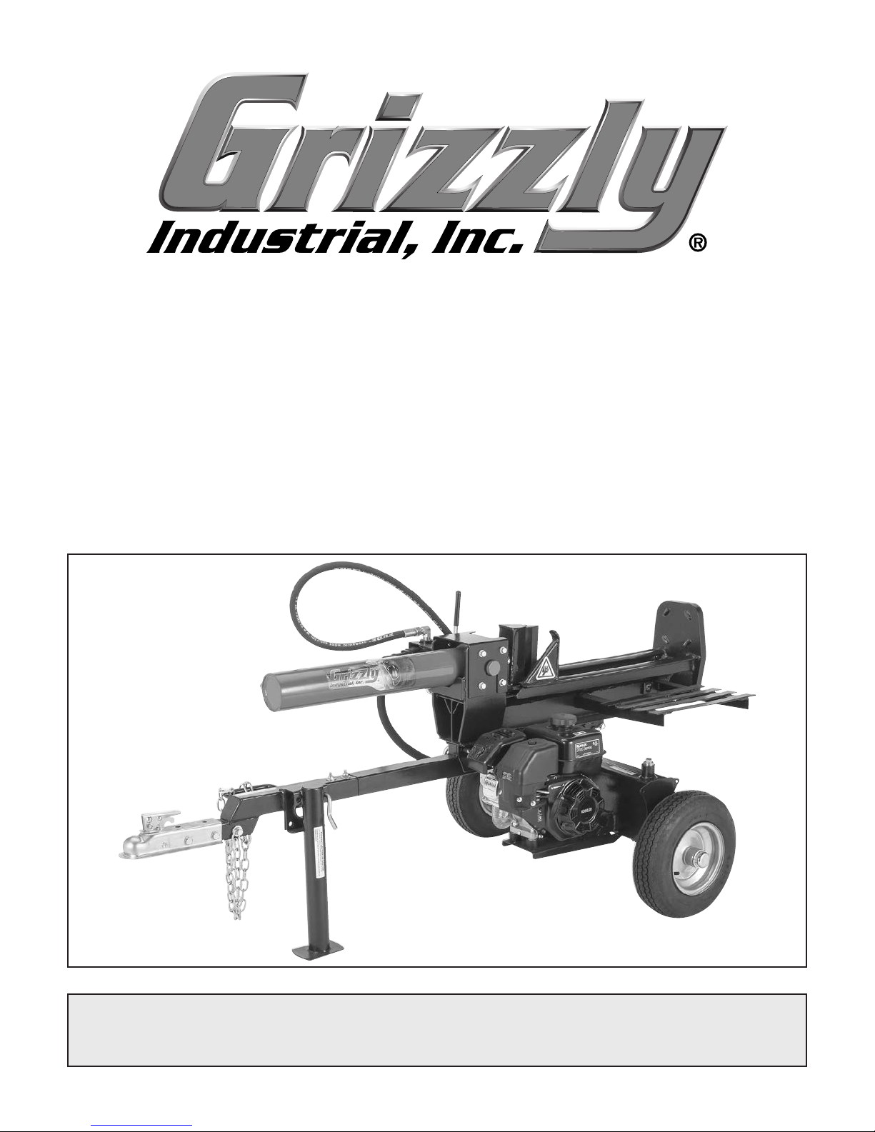
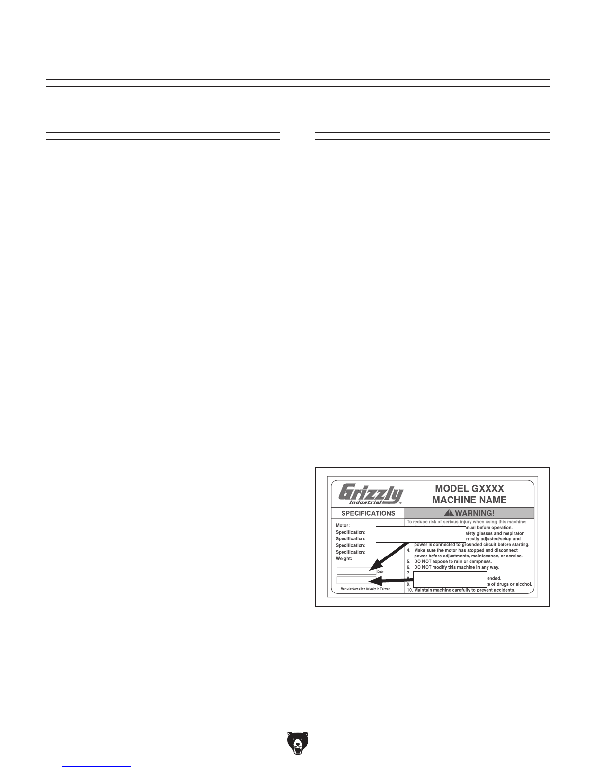
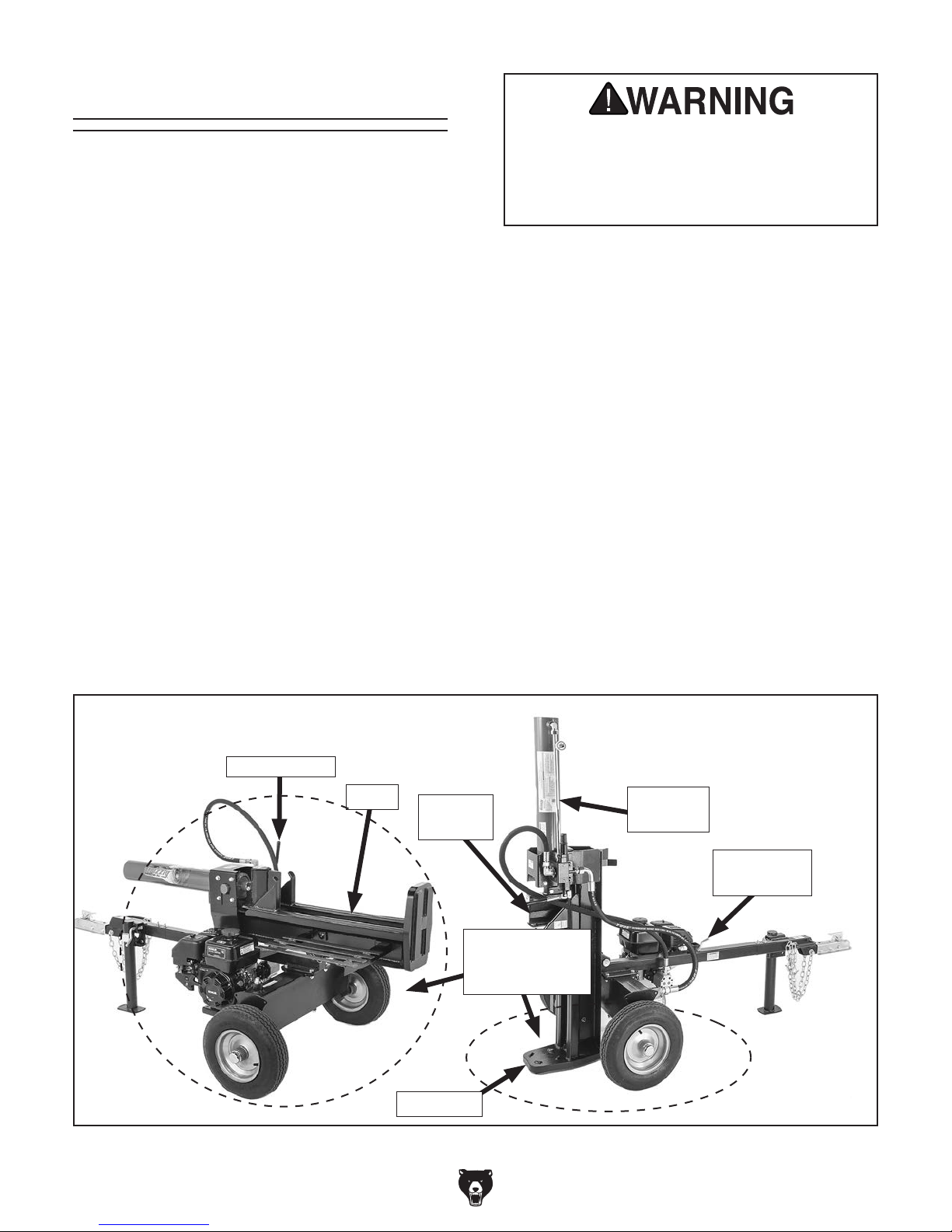
Become familiar with the names and locations of the controls and features shown below to better understand
the instructions in this manual.
F
H
G
E
D
I
J
K
L
C
B
A
A. 2" Tow Bar Coupler
B. Coupler Lock Lever
C. Hydraulic Tank Filter
D. Beam Lock Pin
E. Hydraulic Pump
F. Control Lever
G. Hydraulic Cylinder Assembly
H. Splitting Wedge
I. Dislodger
J. Beam
K. Foot Plate
M
N
O
U
S
T
L. Log Table
M. Gas Cap
N. Hydraulic Tank
O. Vented Cap with Dipstick
P. Tubeless Tire
Q. Kohler Gasoline Engine
R. Engine Controls (refer to Page 5 for details)
S. Support Leg Lock Pin
T. Support Leg
U. Safety Chain
R
Q
P
using machine.
-3-
Page 6
Model T27710 (Mfd. Since 04/16)
Controls &
To reduce your risk of
serious injury, read this
entire manual BEFORE
Components
E. Splitting Wedge: 7" high-carbon steel wedge
delivers 22 tons of ram force to split logs in
half.
using machine.
Refer to Figures 1–4 and the following descriptions to become familiar with the basic controls
and components of this machine. Understanding
these items and how they work will help you
understand the rest of the manual and stay safe
when operating this machine.
Log Splitter Controls
A
B
D
C
E
F
F. Hydraulic Cylinder: 4" x 23" cylinder sup-
plies 3600 PSI of force using 23
operate splitting wedge.
G. Beam Lock Pin: Secures beam horizontally
for jobsite towing or horizontal operation.
H. Hydraulic Tank Filter: Removes contami-
nants from hydraulic fluid flowing back to
hydraulic tank.
L
1
⁄8" stroke to
I
J
K
H
Figure 1. Log splitter controls.
A. Foot Plate: Supports log being split.
B. Beam: Stabilizes length of log being split.
C. Dislodger: Removes log from splitting wedge
after splitting operation is complete.
D. Control Lever: When placed in forward
position (toward foot plate), splitting wedge
moves into log and splits it in half. When
placed in full REVERSE, the splitting wedge
retracts, the lever automatically moves to
NEUTRAL, and wedge stops moving.
-4-
G
Figure 2. Hydraulic tank components.
I. Log Table: Temporarily supports logs before
they are loaded onto beam for splitting.
1
J. Hydraulic Tank: Holds 3
ASLE H-150, universal hydraulic fluid, or ISO
32 equivalent hydraulic fluid for log splitter
operations.
K. Vented Cap: Vents hot gases and fluid from
hydraulic tank. Features dipstick for checking
tank fluid level.
L. Hydraulic Tank Drain Plug: Remove to
drain hydraulic tank fluid.
⁄2 gallons of AW-32,
Page 7
Model T27710 (Mfd. Since 04/16)
Components
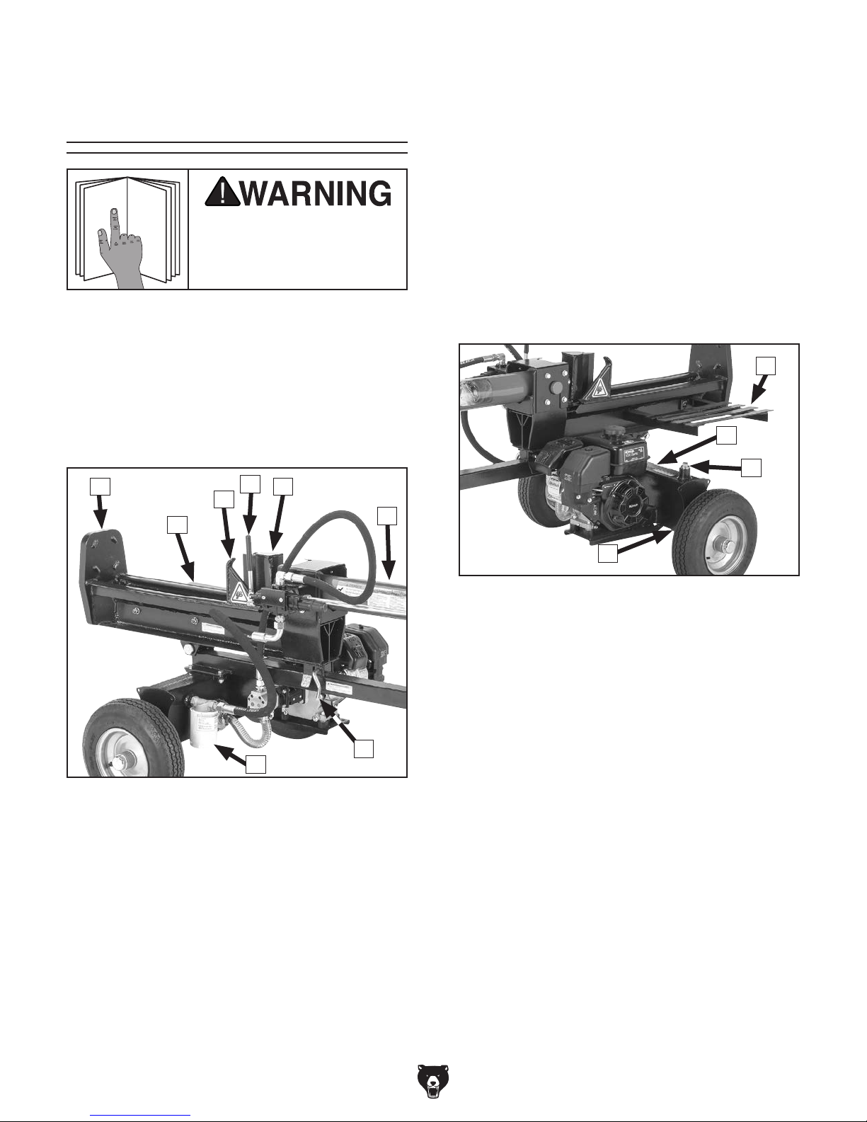
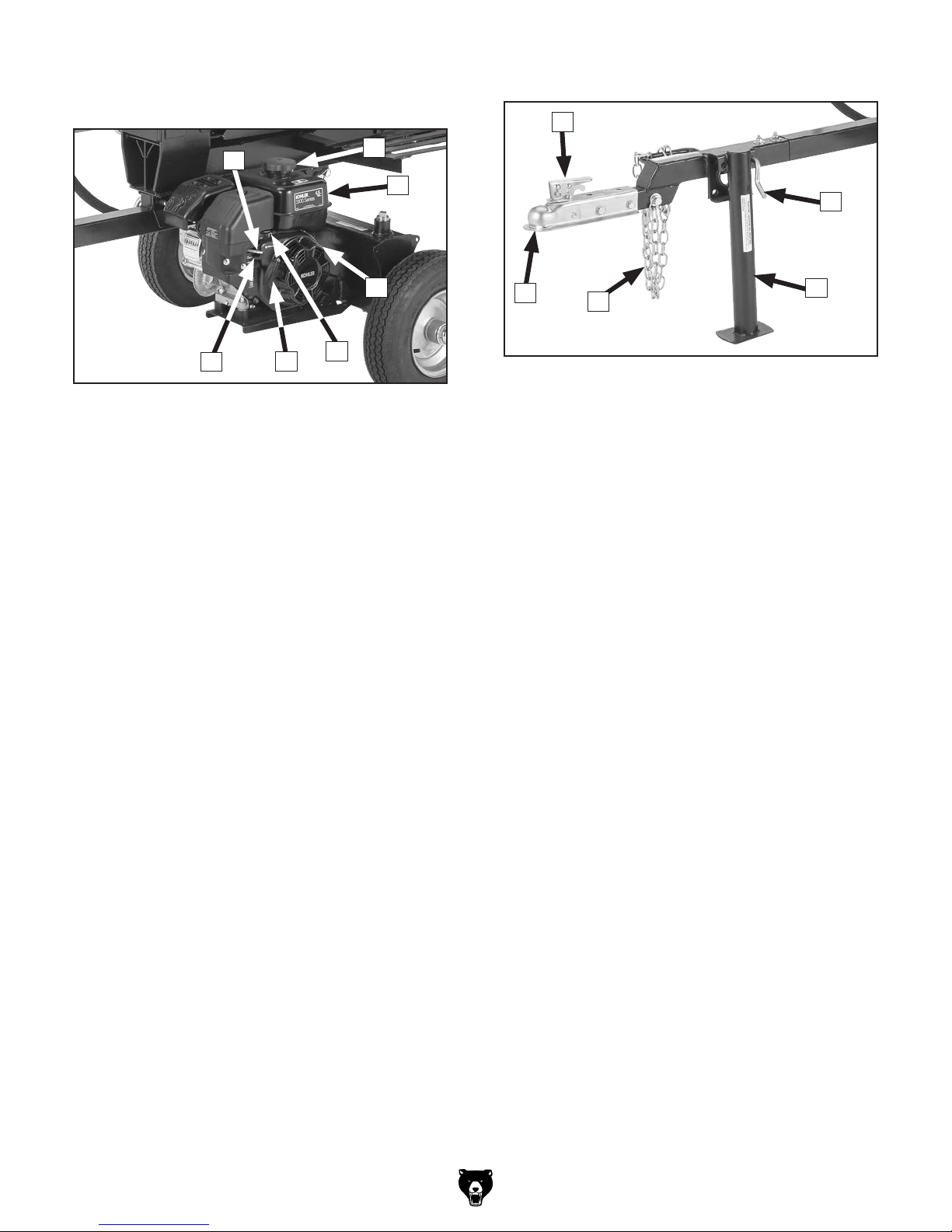
Towing ControlsKohler Engine Controls &
T
N
M
O
U
P
S
Figure 3. Kohler engine controls and
components.
M. Choke Lever: Controls choke valve and
air-to-fuel ratio in engine. Move lever left to
ON (I) position when starting engine when it
is cold. Move lever right to OFF position (O)
after engine starts. Use this position if starting
engine when it is already warm.
N. Gas Cap: Remove to fill fuel tank.
O. Fuel Tank: Fill with clean, fresh gasoline.
Refer to Kohler engine manual to select
required fuel type. Avoid overfilling.
P. ON/OFF Switch: Turn to ON position (I)
before starting engine. Turn to OFF position
(O) to shut engine OFF.
R
Q
X
Figure 4. Towing controls and components.
T. Coupler Lock Lever: Push down to lock
coupler onto vehicle tow ball; lift up to release
coupler from vehicle tow ball. Features a hole
for inserting a pin or padlock.
U. Support Leg Lock Pin: When engaged,
secures support leg in up or down position.
When disengaged, allows support leg to
pivot.
V. Support Leg: Supports weight of log splitter
and provides stability during splitting operations. Leg can be lowered for operation or
raised for towing.
W. Safety Chains: Ensure log splitter remains
attached to towing vehicle if coupler accidentally separates from towing hitch ball while
towing.
W
V
Q. Throttle Control Lever: Regulates amount
of air entering engine, thereby controlling
its speed. Move halfway between SLOW
(turtle) and FAST (rabbit) when starting
engine. Adjust lever as needed for operation.
R. Starter Rope: Pull several times to start
engine and allow fuel to flow into engine.
Slowly retract to engine once it starts.
S. Fuel Shutoff Lever: Controls flow of fuel
from tank to carburetor. Turn to ON position
before engine startup. Turn to OFF position
(O) when shutting down engine, or before
towing to avoid flooding engine.
X. 2" Tow Bar Coupler: Connects log splitter to
2" trailer hitch ball for towing.
-5-
Page 8

Model T27710 (Mfd. Since 04/16)
22-TON LOG SPLITTER WITH KOHLER ENGINE
Product Dimensions:
...............................................................................................................................
Weight
(side-to-side) x Depth (front-to-back) x Height ..................................................................................
Width
Footprint
Shipping Dimensions:
Type
Content
Weight
Length
Must
(Length x Width) ...............................................................................................................................
........................................................................................................................................................................ Wood Crate
...............................................................................................................................
...............................................................................................................................
x Width x Height ...............................................................................................................................
Ship Upright ...............................................................................................................................
Machine Data Sheet
MODEL T27710
............................................. 388
x 84 x 41 in.
42-1/2
..........85
........................................... Machine
............................................. 441
......45
x 34 x 22 in.
..................................Yes
lbs.
x 44 in.
lbs.
Engine Information:
Manufacturer
Horsepower
Bore
...............................................................................................................................
Stroke
Displacement
Capacity ...............................................................................................................................
Oil
Hydraulic Information:
Hydraulic
Automatic
Maximum Pump Pressure ............................................................................................................................................ 3600 PSI
Pump
Hydraulic
Hydraulic
Type ...............................................................................................................................
Filter
Cycle
Main Specifications:
Operation Information
...............................................................................................................................
...............................................................................................................................
..................................... 68
...............................................................................................................................
................................................................................................................................................................. 196 CC
Cylinder Size (Diameter x Length) ...............................................................................................................4 x 23 in.
Cylinder Return ...............................................................................................................................
Rating ...............................................................................................................................
Tank Capacity ...............................................................................................................................
Oil Type ............................................................
Time ...............................................................................................................................................................13 Seconds
Ram
Force ...............................................................................................................................
Length of Log ...............................................................................................................................
Max.
Stroke Length ............................................................................................................................................23-1/8 in.
Max.
Automatic
Vertical
Cylinder Return ...............................................................................................................................
& Horizontal Operation ...............................................................................................................................
AW-32,
ASLE H-150, Universal Hydraulic Oil, or ISO 32 equivalent
..................................... Kohler
.......................................6.5
.................................. 54
......................................0.63
.....................Yes
....................11
................ Replaceable,
.............................22
GPM, 2-Stage
...............3-1/2
.............25-5/8
HP
mm (2.7 in.)
mm (2.1 in.)
qt.
gal.
Spin-Off
Tons
in.
...........Yes
....Yes
Construction Information
Splitter Wedge ..............................................................................................................................................Carbon Steel
Wedge Height ...............................................................................................................................
Splitter
...............................................................................................................................
Axle
Hoses
...............................................................................................................................
-6-
.................7
................................Carbon
................................Wire
in.
Steel
Braid
Page 9

Model T27710 (Mfd. Since 04/16)
Chassis:
Type
...............................................................................................................................
Tow
Ball Receiver ...............................................................................................................................
...............................................................................................................................
Wheels
Tires
...............................................................................................................................
Tire
Max. Load ............................................................................................................................................................... 590 lbs.
Tire
Rating (Max. Speed) ...............................................................................................................................
Wheel
Bearing Type ...............................................................................................................................
Jackstand
Other Specifications:
Country of Origin ............................................................................................................................................................... China
Warranty
Serial
ISO
Certified
Assembly
Features:
Automatic
25-5/8
22-Ton
2"
Tow Ball Coupler
45
MPH Tow Rating
Carbon
Carbon
Included ...............................................................................................................................
...............................................................................................................................
Number Location ...............................................................................................................................
9001 Factory ..................................................................................................................................................................
by a Nationally Recognized Testing Laboratory ...................................................................................................... No
Time ......................................................................................................................................................... 30 Minutes
Cylinder Return
in. Log Capacity
Splitter Ram Force
Steel Splitter Wedge
Steel Frame
........................................Carbon
............ 2
...........................Steel,
...................... Tubeless
............................................ 1
in. Ball Coupler
16 in. x 4.80-8
................45
............Tapered
................................Yes
................. ID
Steel
Integral Hub
MPH
Roller
Year
Label
Yes
-7-
Page 10

Model T27710 (Mfd. Since 04/16)
SECTION 1: SAFETY
For Your Own Safety, Read Instruction
Manual Before Operating This Machine
The purpose of safety symbols is to attract your attention to possible hazardous conditions.
This manual uses a series of symbols and signal words intended to convey the level of importance of the safety messages. The progression of symbols is described below. Remember that
safety messages by themselves do not eliminate danger and are not a substitute for proper
accident prevention measures. Always use common sense and good judgment.
Indicates an imminently hazardous situation which, if not avoided,
WILL result in death or serious injury.
Indicates a potentially hazardous situation which, if not avoided,
COULD result in death or serious injury.
Indicates a potentially hazardous situation which, if not avoided,
MAY result in minor or moderate injury. It may also be used to alert
against unsafe practices.
This symbol is used to alert the user to useful information about
NOTICE
proper operation of the machine.
Safety Instructions for Machinery
OWNER’S MANUAL. Read and understand this
owner’s manual BEFORE using machine.
TRAINED OPERATORS ONLY. Untrained operators have a higher risk of being hurt or killed.
Only allow trained/supervised people to use this
machine. When machine is not being used, disconnect power, remove switch keys, or lock-out
machine to prevent unauthorized use—especially
around children. Make workshop kid proof!
DANGEROUS ENVIRONMENTS. Do not use
machinery in areas that are wet, cluttered, or have
poor lighting. Operating machinery in these areas
greatly increases the risk of accidents and injury.
MENTAL ALERTNESS REQUIRED. Full mental
alertness is required for safe operation of machinery. Never operate under the influence of drugs or
alcohol, when tired, or when distracted.
ELECTRICAL EQUIPMENT INJURY RISKS. You
can be shocked, burned, or killed by touching live
electrical components or improperly grounded
machinery. To reduce this risk, only allow qualified
service personnel to do electrical installation or
repair work, and always disconnect power before
accessing or exposing electrical equipment.
DISCONNECT POWER FIRST.
nect machine from power supply BEFORE making
adjustments, changing tooling, or servicing machine.
This prevents an injury risk from unintended startup
or contact with live electrical components.
EYE PROTECTION. Always wear ANSI-approved
safety glasses or a face shield when operating or
observing machinery to reduce the risk of eye
injury or blindness from flying particles. Everyday
eyeglasses are NOT approved safety glasses.
Always discon-
-8-
Page 11

Model T27710 (Mfd. Since 04/16)
WEARING PROPER APPAREL. Do not wear
clothing, apparel or jewelry that can become
entangled in moving parts. Always tie back or
cover long hair. Wear non-slip footwear to reduce
risk of slipping and losing control or accidentally
contacting cutting tool or moving parts.
HAZARDOUS DUST. Dust created by machinery
operations may cause cancer, birth defects, or
long-term respiratory damage. Be aware of dust
hazards associated with each workpiece material. Always wear a NIOSH-approved respirator to
reduce your risk.
HEARING PROTECTION. Always wear hearing protection when operating or observing loud
machinery. Extended exposure to this noise
without hearing protection can cause permanent
hearing loss.
REMOVE ADJUSTING TOOLS. Tools left on
machinery can become dangerous projectiles
upon startup. Never leave chuck keys, wrenches,
or any other tools on machine. Always verify
removal before starting!
USE CORRECT TOOL FOR THE JOB. Only use
this tool for its intended purpose—do not force
it or an attachment to do a job for which it was
not designed. Never make unapproved modifications—modifying tool or using it differently than
intended may result in malfunction or mechanical
failure that can lead to personal injury or death!
AWKWARD POSITIONS. Keep proper footing
and balance at all times when operating machine.
Do not overreach! Avoid awkward hand positions
that make workpiece control difficult or increase
the risk of accidental injury.
CHILDREN & BYSTANDERS. Keep children and
bystanders at a safe distance from the work area.
Stop using machine if they become a distraction.
GUARDS & COVERS. Guards and covers reduce
accidental contact with moving parts or flying
debris. Make sure they are properly installed,
undamaged, and working correctly BEFORE
operating machine.
FORCING MACHINERY. Do not force machine.
It will do the job safer and better at the rate for
which it was designed.
NEVER STAND ON MACHINE. Serious injury
may occur if machine is tipped or if the cutting
tool is unintentionally contacted.
STABLE MACHINE. Unexpected movement during operation greatly increases risk of injury or
loss of control. Before starting, verify machine is
stable and mobile base (if used) is locked.
USE RECOMMENDED ACCESSORIES. Consult
this owner’s manual or the manufacturer for recommended accessories. Using improper accessories will increase the risk of serious injury.
UNATTENDED OPERATION. To reduce the
risk of accidental injury, turn machine OFF and
ensure all moving parts completely stop before
walking away. Never leave machine running
while unattended.
MAINTAIN WITH CARE. Follow all maintenance
instructions and lubrication schedules to keep
machine in good working condition. A machine
that is improperly maintained could malfunction,
leading to serious personal injury or death.
DAMAGED PARTS. Regularly inspect machine
for damaged, loose, or mis-adjusted parts—or
any condition that could affect safe operation.
Immediately repair/replace BEFORE operating
machine. For your own safety, DO NOT operate
machine with damaged parts!
MAINTAIN POWER CORDS. When disconnecting cord-connected machines from power, grab
and pull the plug—NOT the cord. Pulling the cord
may damage the wires inside. Do not handle
cord/plug with wet hands. Avoid cord damage by
keeping it away from heated surfaces, high traffic
areas, harsh chemicals, and wet/damp locations.
EXPERIENCING DIFFICULTIES. If at any time
you experience difficulties performing the intended operation, stop using the machine! Contact our
Technical Support at (570) 546-9663.
-9-
Page 12

Model T27710 (Mfd. Since 04/16)
Additional Safety for Log Splitters
HYDRAULIC PRESSURE RELIEF VALVE.
Serious injury or death can occur from getting hands or fingers crushed by logs or amputated
by splitting wedge. Severe burns can be caused by touching hot parts during operation. Death
can result from getting accidentally injected by hydraulic fluid or inhaling carbon monoxide.
Workpieces can be ejected by splitter and strike operator or bystanders. To minimize risk of
injury, anyone operating this machine MUST completely heed hazards and warnings below.
HOT ENGINE. Motor and other parts of machine
get hot during operation. Allow to cool before
placing hands near motor, hydraulic cylinder, or
hydraulic lines, adding fuel, or performing any
service or maintenance.
SUPPORTING LOGS BY HAND. Never use any
part of your body to guide or steady a log when
ram is moving. Failure to follow this instruction
can result in crushing or amputation injuries.
ADEQUATE VENTILATION. The log splitter
engine produces carbon monoxide, which is a
poisonous gas. Make sure work area is adequately ventilated. Never operate this machine indoors
or in any type of enclosed area.
FLUID INJECTION. Fluid pressures developed
from this machine are up to 3000 PSI, which are
high enough to penetrate your skin and enter your
bloodstream. Hydraulic fluid injected into your
bloodstream is a medical emergency. If not treated immediately, this blood poisoning could result
in an aggressive infection, amputation, or death.
Keep body parts away from any high-pressure
hydraulic leak.
CORRECT USAGE. Never split wood across
grain or use log splitter to split concrete blocks,
rocks, or to bend metal.
PROTECTING CHILDREN. Keep children away
from log splitter at all times! It is not a toy. Never
allow any child to climb or ride on log splitter.
FUEL SPILLS. Fuel exposed to hot engine components may ignite. Thoroughly clean all fuel
spills before starting engine.
TROUBLESHOOTING. If you suspect a hydraulic
leak, DO NOT use your hand or fingers to locate
it. Instead, keep your skin at least 12" away from
potential leaking areas and move a strip of cardboard to where leak may exist and watch to see
if hydraulic oil is sprayed onto cardboard. Some
high-pressure streams can be almost invisible to
the naked eye.
Adjusting pressure limit screw may lead to hydraulic explosion and seriously injure operator and
bystanders. The pressure relief valve is factory set
and should not be adjusted unless by professional
hydraulic technician.
TOWING. This log splitter is not designed to be
towed on logging roads, forest service roads, public roads, or highways. This machine is designed
for job site towing only where speed will not
exceed maximum speed listed in Data Sheet.
WORKPIECE SELECTION. Logs with extensive
knotting may be difficult or impossible to split.
Making repeated attempts to split an unsuitable
log will increase wear on the pressure relief valve,
hydraulic lines, and increase risk of operator
injury.
CORRECT USAGE. Never attempt to split more
than one log at a time. Doing so may cause logs
to fly off splitter with great force, resulting in serious injury or death.
MACHINE LOCATION. Never leave splitter running unattended, always block wheels to prevent
rolling, and store unit in locked location.
-10 -
Page 13
Model T27710 (Mfd. Since 04/16)
SECTION 2: SETUP
This machine was carefully packaged for safe
transport. When unpacking, separate all enclosed
items from packaging materials and inspect them
for shipping damage.
,
please
IMPORTANT:
you are completely satisfied with the machine and
have resolved any issues between Grizzly or the
shipping agent. You MUST have the original pack-
aging to file a freight claim. It is also extremely
helpful if you need to return your machine later.
Keep children and pets away
from plastic bags or packing
materials shipped with this
get help from other people
The following items are needed, but not included,
for the setup/assembly of this machine.
Needed for Setup
This machine presents
serious injury hazards
to untrained users. Read
through this entire manual to become familiar with
the controls and operations before starting the
machine!
Wear safety glasses and
gloves during entire setup
process!
HEAVY LIF T!
Straining or crushing injury
may occur from improperly
lifting machine or some of
its parts. To reduce this risk,
and use a forklift (or other
lifting equipment) rated for
weight of this machine.
Description Qty
• Safety Glasses (for each person) ............... 1
• Gloves (for each person) ............................ 1
• Another Person .......................................... 1
• Adjustable Wrench ..................................... 1
• Flat Head Screwdriver ................................ 1
• Multi-Purpose Grease ................ As Needed
• Open-End Wrenches/Sockets 13mm ......... 2
• Open-End Wrenches/Sockets 17mm ......... 2
• Open-End Wrenches/Sockets 19mm ......... 2
• Phillips Head Screwdriver........................... 1
• Pliers........................................................... 1
• Rubber Hammer ......................................... 1
• Hydraulic Fluid AW-32/ISO 32 .. 3.5 Gallons
• Engine Oil .......... See Kohler Engine Manual
• Gasoline ..................................... As Needed
Unpacking
If items are damaged
call us immediately at (570) 546-9663.
Save all packaging materials until
SUFFOCATION HAZARD!
machine. Discard immediately.
-11-
Page 14
Model T27710 (Mfd. Since 04/16)
Inventory
The following is a list of items shipped with your
machine. Before beginning setup, lay these items
out and inventory them.
If any non-proprietary parts are missing (e.g. a
nut or a washer), we will gladly replace them; or
for the sake of expediency, replacements can be
obtained at your local hardware store.
A
C
B
D
NOTICE
If you cannot find an item on this list, carefully check around/inside the machine and
packaging materials. Often, these items get
lost in packaging materials while unpacking or they are pre-installed at the factory.
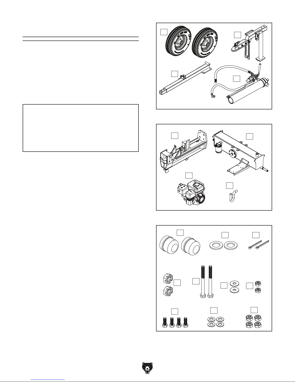
Box Inventory (Figures 5–6) Qty
A. Wheel Assemblies ...................................... 2
B. Support Leg and Coupler Assembly .......... 1
C. Rear Frame Tube ....................................... 1
D. Hydraulic Cylinder Assembly...................... 1
E. Log Splitter Assembly ................................ 1
F. Hydraulic Tank Assembly ........................... 1
G. Kohler Engine 3000, 6.5HP, 196CC ........... 1
H. Suction Hose .............................................. 1
Hardware Bag Contents (Figure 7) Qty
I. Axle Caps (Wheel) ..................................... 2
J. Flat Washers 20mm (Wheel)...................... 2
K. Cotter Pins 4 x 36 (Wheel) ......................... 2
L. Slotted Hex Nuts M20-2.5 (Wheel) ............ 2
M. Hex Bolts M10-1.5 x 70 (Frame Tube) ........ 2
N. Flat Washers 10mm (Frame Tube) ............. 2
O. Lock Nuts M10-1.5 (Frame Tube) ............... 2
P. Hex Bolts M12-1.75 x 35 (Frame/Tank) ...... 4
Q. Flat Washers 12mm (Frame/Tank) ............. 4
R. Lock Nuts M12-1.75 (Frame/Tank) .............. 4
Figure 5. Box inventory 1.
E
G
Figure 6. Box inventory 2.
I
L
M
F
H
J K
N
O
-12-
P
Figure 7. Hardware inventory.
Q
R
Page 15
Model T27710 (Mfd. Since 04/16)
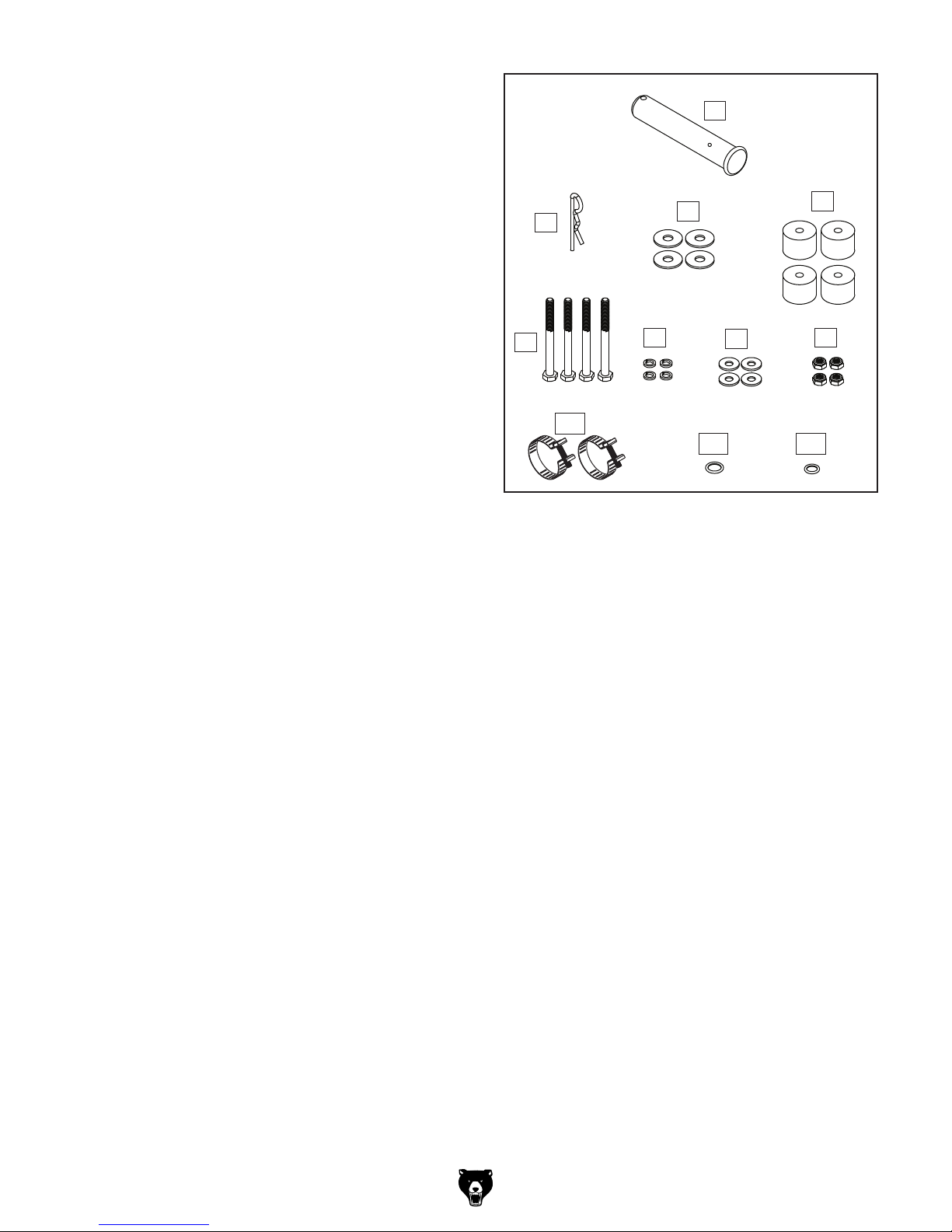
Addl. Hardware Bag Contents (Figure 8) Qty
S. Clevis Pin 21 x 126mm (Cylinder/Beam) .... 1
3
T. Hairpin Cotter Pin 1
⁄4" x 21⁄2 "
(Cylinder/Beam) .......................................... 1
U. Fender Washers 10mm (Engine) ................ 4
V. Rubber Spacers (Engine) ........................... 4
W. Hex Bolts M8-1.25 x 65 (Engine) ................ 4
X. Fender Washers 8mm (Engine) ................. 4
Y. Lock Washers 8mm (Engine) ..................... 4
Z. Lock Nuts M8-1.25 (Engine) ....................... 4
AA. Hose Clamps (Suction Hose) ..................... 2
AB. O-Ring 11. 2 x 2.4mm (High Press. Hose) . . 1
AC. O-Ring 17 x 2.5mm (Hydraulic Filter) ......... 1
S
T
W
U
X
Y
AA
AB
Figure 8. Additional hardware inventory.
V
Z
AC
-13-
Page 16
Model T27710 (Mfd. Since 04/16)
Site Considerations
Weight Load
for the weight
of your machine. Make sure that the surface upon
of the machine, additional equipment that may be
Physical Environment
The physical environment where the machine
is operated is important for safe operation and
longevity of components. For best results, operate this machine in a dry environment that is
free from excessive moisture, hazardous chemicals, airborne abrasives, or extreme conditions.
Extreme conditions for this type of machinery are
generally those where the ambient temperature
range is outside 41°–104°F; the relative humidity
range is outside 20–95% (non-condensing); or
the environment is subject to vibration, shocks,
or bumps.
Shadows, glare, or strobe effects that may distract
Space Allocation
Consider the largest size of workpiece that will
be processed through this machine and provide
enough space around the machine for adequate
operator material handling or the installation of
auxiliary equipment. With permanent installations,
leave enough space around the machine to open
or remove doors/covers as required by the maintenance and service described in this manual.
See below for required space allocation.
Refer to the Machine Data Sheet
which the machine is placed will bear the weight
installed on the machine, and the heaviest workpiece that will be used. Additionally, consider the
weight of the operator and any dynamic loading
that may occur when operating the machine.
Lighting
Lighting around the machine must be adequate
enough that operations can be performed safely.
or impede the operator must be eliminated.
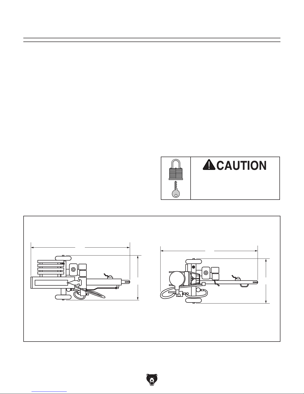
Horizontal Operation
Important: Ensure log splitter is at least 7' from any dry leaves or combustibles, and at least 25' from
any fresh air intake supplying working or living areas. Allow enough space on all sides to move logs to
and from splitter.
-14-
84"
Figure 9. Working clearances.
Children or untrained people
may be seriously injured by
this machine. Only install in an
access restricted location.
Vertical Operation
421/2"
87"
421/2"
Page 17
Model T27710 (Mfd. Since 04/16)
Assembly
The machine must be fully assembled before it
can be operated. Before beginning the assembly
process, refer to
all
cess goes smoothly, clean all
that have any
heavy-duty rust preventative
tory (if applicable).
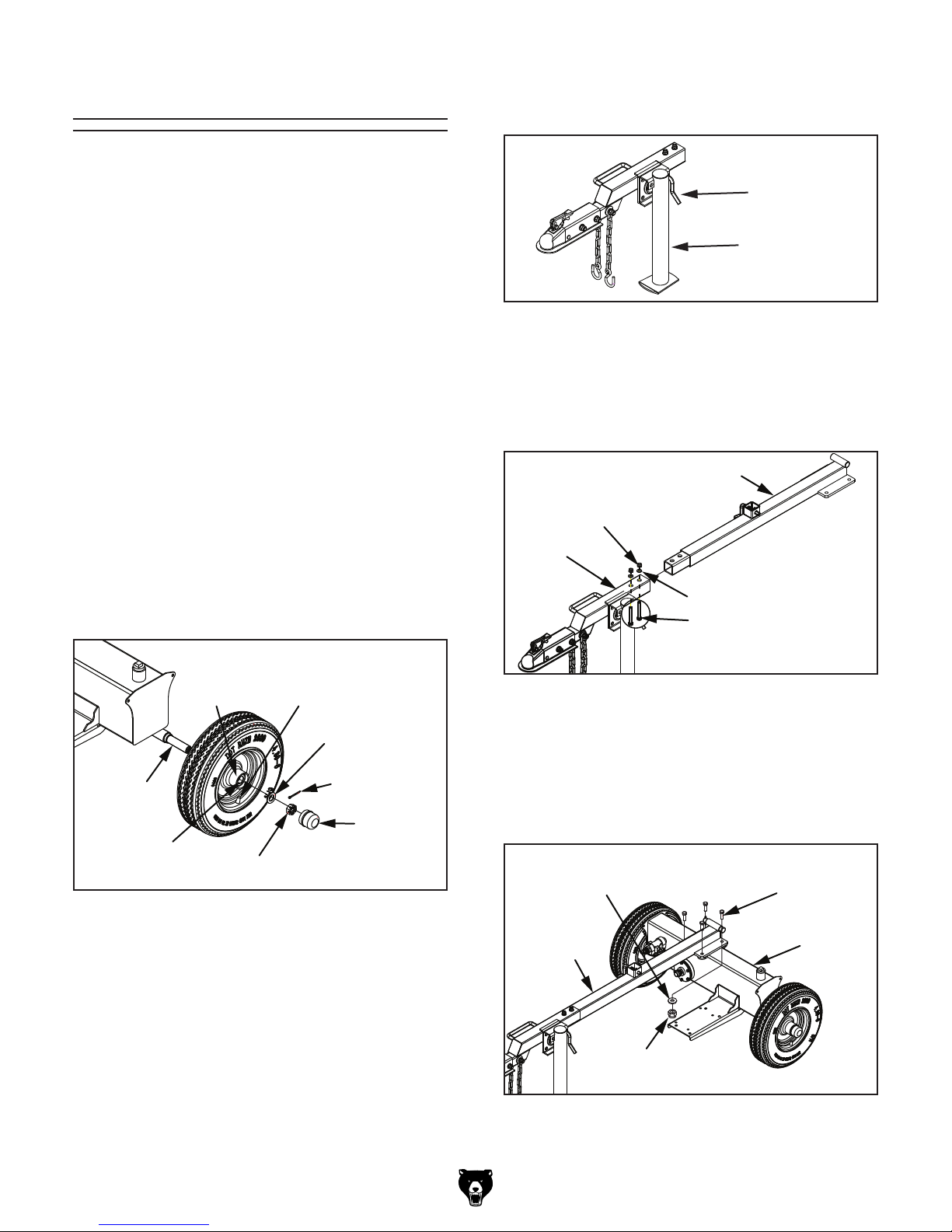
5. Pull lock pin out and pivot support leg until pin
locks leg in down position (see Figure 11).
Needed for Setup and gather
listed items. To make sure the assembly pro-
parts
applied by the fac-
To assemble log splitter:
1. Wipe dab of multi-purpose grease onto spin-
dle and wheel bearing (see Figure 10), and
with valve stem facing outward, slide wheel
onto axle until it stops.
2. Place 20mm flat washer with M20-2.5
slotted hex nut onto axle, then place 4 x
36mm cotter pin through hole in spindle end
(see Figure 10).
3. Bend both cotter pin tangs so wheel is held
onto axle, and tap axle cap (see Figure 10)
onto wheel.
Lock Pin
Support Leg
Figure 11. Support leg locked in down position.
6. Attach front frame tube with support leg to
rear frame tube with (2) M10-1.5 x 70 hex
bolts, (2) 10mm flat washers, and (2) M10-1.5
lock nuts (see Figure 12).
Rear Frame Tube
Lock Nut M10-1.5
Front
Frame
Tube
Flat Washer 10mm
Hex Bolt M10-1.5 x 70
Wheel
Bearing
Axle
Spindle
Figure 10. Installing wheel onto axle.
4. Repeat Steps 1–3 to install the other wheel.
Slotted Hex Nut
Valve Stem
Flat Washer 20mm
Cotter Pin
4 x 36
Axle Cap
Figure 12. Installing front frame tube onto rear
frame tube.
7. Place frame tube onto hydraulic tank and
attach it with (4) M12-1.75 x 35 hex bolts, (4)
12mm flat washers, and (4) M12-1.75 lock
nuts, as shown in Figure 13.
Hex Bolt
Flat Washer 12mm
Frame
Tube
Lock Nut
M12-1.75
Figure 13. Installing frame tube onto tank.
M12-1.75 x 35
Hydraulic
Tank
-15-
Page 18
Model T27710 (Mfd. Since 04/16)
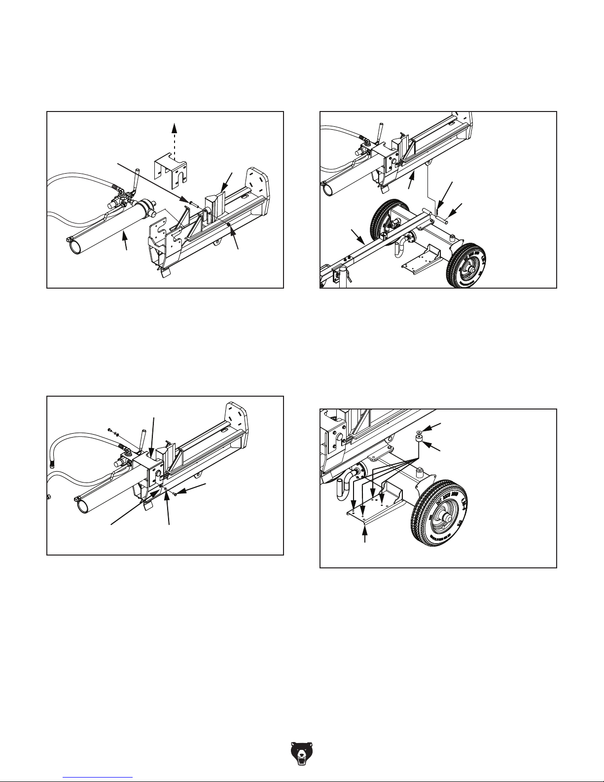
8. Remove cylinder cover, then attach hydraulic
cylinder to splitting wedge with pre-installed
(1) M12-1.75 x 65 hex bolt and (1) M12-1.75
lock nut (see Figure 14).
10. With help of assistant, lift hydraulic cylinder
and beam onto frame tube. Secure with (1)
3
21 x 126mm clevis pin and (1) 1
⁄4" x 21⁄2"
hairpin cotter pin (see Figure 16).
Hex Bolt
M12-1.75 x 65
Cylinder
Cover
Hydraulic
Cylinder
Splitting
Wedge
Lock Nut
M12-1.75
Figure 14. Attaching hydraulic cylinder to
splitting wedge.
9. Re-install cylinder cover with (8) M10-1.5 x
20 hex bolts, (8) 10mm lock washers, and
(8) 10mm flat washers that were removed in
Step 8 (see Figure 15).
Cylinder Cover
Hairpin
Cotter Pin
Beam
Frame
Tube
Clevis Pin
Figure 16. Attaching hydraulic cylinder and
beam to frame tube.
11. Remove any paint chips or foreign material
from engine mounting pad, then place (4)
rubber spacers—each with a 10mm fender
washer—over holes on engine mounting pad
(see Figure 17).
Fender Washer 10mm
Hex Bolt
M10-1.5 x 20
Flat Washer
10mm
Lock Washer
10mm
Figure 15. Hydraulic cylinder cover re-installed.
Rubber Spacer
Mounting Pad
Figure 17. Installing rubber spacers and flat
washers onto motor mounting pad.
-16 -
Page 19
Model T27710 (Mfd. Since 04/16)
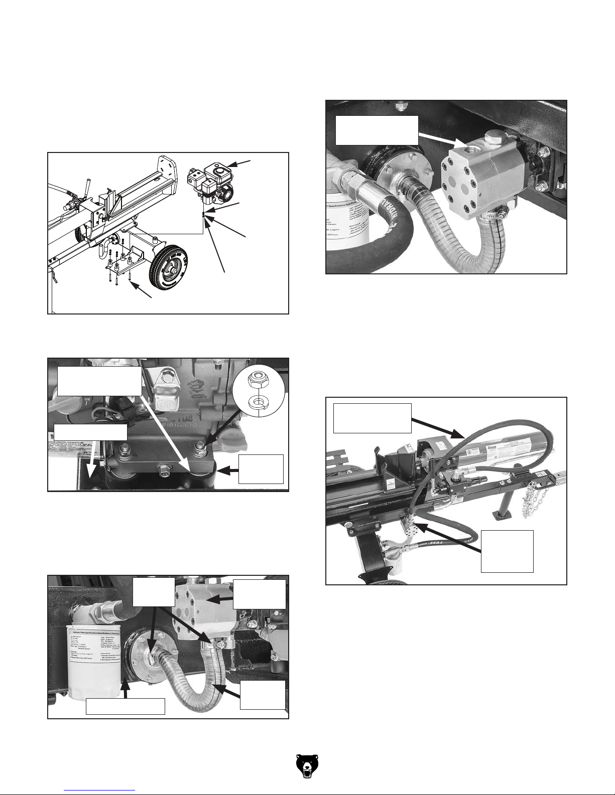
12. Attach engine to mounting pad with (4)
M8-1.25 x 65 hex bolts, (4) 8mm fender
washers, (4) 8mm lock washers, and (4)
M8-1.25 lock nuts (see Figures 18–19).
Tighten fasteners evenly, in alternating pattern, to reduce risk of cracking mounting
flange. DO NOT overtighten!
Engine
Lock Nut
M8-1.25
Lock Washer
8mm
14. Remove plastic cap from pump pressure port
and add a couple of tablespoons of hydraulic
fluid into pressure port (see Figure 21).
Location to Add
Hydraulic Fluid
Flat Washer 8mm
Hex Bolt M8-1.25 x 65
Figure 18. Installing rubber spacers and flat
washers onto engine mounting pad.
Fender Washer
10mm
Mounting Pad
Rubber
Spacer
Figure 19. Engine fastener detail.
13. Attach suction hose to hydraulic pump suc-
tion port and hydraulic tank with hose clamps
(see Figure 20).
Figure 21. Pump pressure port.
15. Unthread plastic plug from high pressure
hose (see Figure 22).
16. Install high pressure hose onto pump pressure
fitting (see Figure 22) with (1) 11.2 x 2.4
O-ring.
High Pressure
Hose
Pump
Pressure
Fitting
Hose
Clamps
Hydraulic Tank
Figure 20. Suction hose attached to hydraulic
pump and hydraulic tank.
Hydraulic
Pump
Suction
Hose
Figure 22. High pressure hose and control lever.
-17-
Page 20

Model T27710 (Mfd. Since 04/16)
17. Remove plastic cap from hydraulic filter fitting
(see Figure 23), and lubricate and install (1)
17 x 2.5mm O-ring on end of fitting.
21. Refer to Kohler engine manual to select
required engine oil type, locate fill plug (see
Figure 24), and fill engine with required oil.
18. Unthread plastic plug from low pressure
return hose (see Figure 23).
19. Install low pressure return hose onto tank
hydraulic filter fitting (see Figure 23), making
sure O-ring stays in place.
Note: Tighten hydraulic hose connector to
18-20 inch/pounds.
Low Pressure
Return Hose
Hydraulic
Filter Fitting
22. Refer to Kohler engine manual to select
required fuel type, locate gas cap (see
Figure 24), and fill engine with required fuel.
Gas Cap
Oil Fill Plug
Figure 24. Engine gas cap and oil fill plug
locations.
Figure 23. Low pressure hose and oil filter
fitting.
20. Make sure log splitter is on level surface, and
fill hydraulic tank with hydraulic fluid. Refer to
Checking/Adding Hydraulic Fluid on Page
29 for specific details.
IMPORTANT: Hydraulic tank is shipped from
factory without hydraulic fluid. It must be filled
before operation!
Damage caused by running log splitter
without hydraulic fluid or engine oil will not
be covered under warranty.
-18-
Page 21
Model T27710 (Mfd. Since 04/16)
Test Run/Break-In
This machine presents
serious injury hazards
to untrained users. Read
through this entire manual
and Kohler engine manual to become familiar with
controls and operations
before starting engine and
using log splitter!
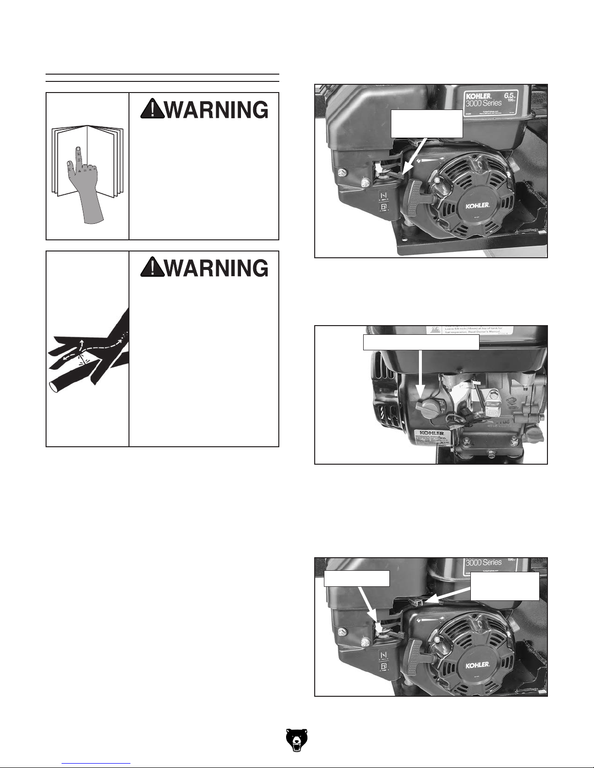
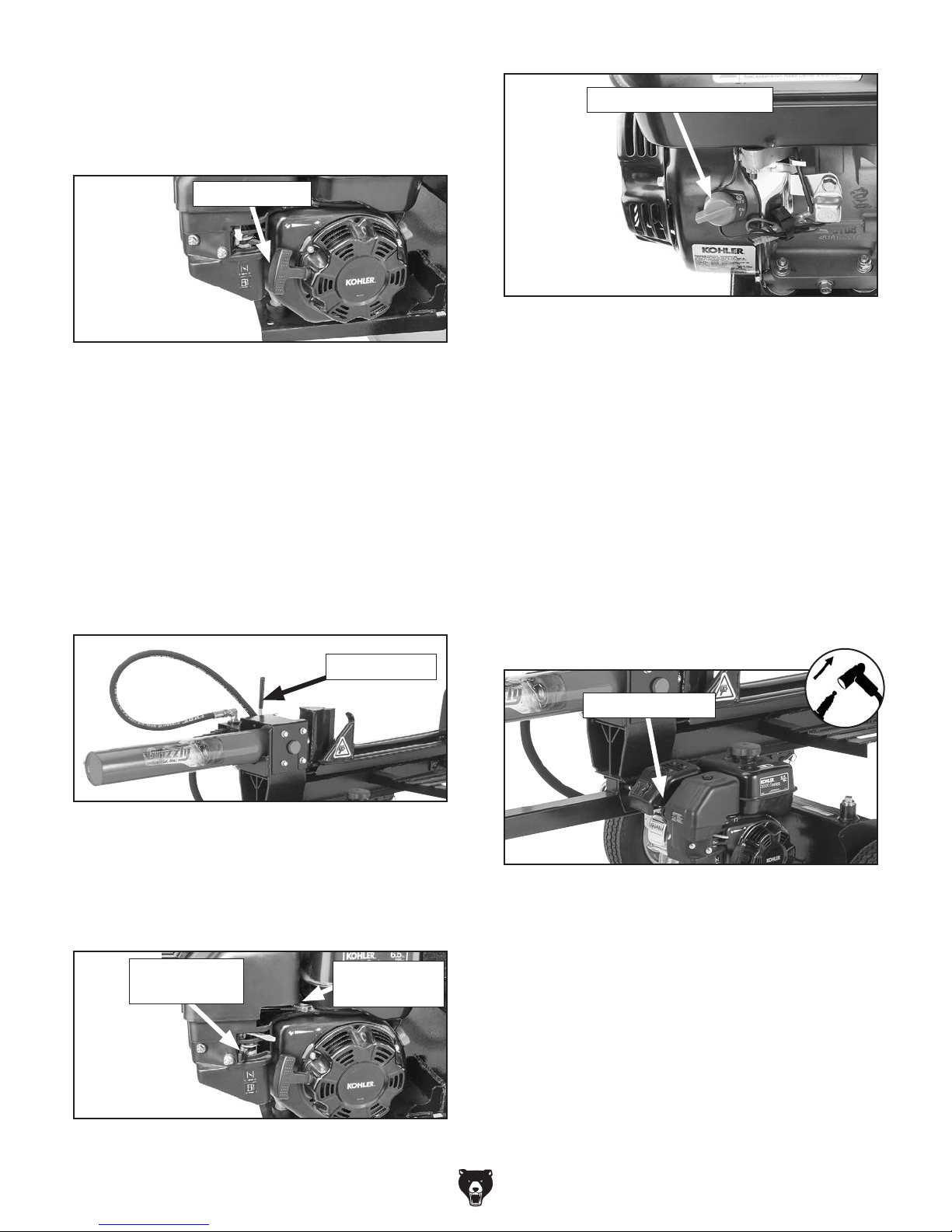
3. Move fuel shutoff lever to ON (I) position, as
shown in Figure 25.
Fuel Shutoff
Lever
Figure 25. Fuel shutoff lever in ON position.
HYDRAULIC INJECTION
HAZARD
Hydraulic fluid leaks can be
under sufficient pressure
to penetrate your skin and
enter your bloodstream. If
fluid is injected into any
part of your body, it is a
medical emergency and
may, if not treated immediately, result in severe infection, permanent disability,
or even death.
IMPORTANT: Do not leave area during test run,
in case there is a problem or a leak.
To test run and break-in log splitter:
1. Read and understand Kohler engine manual
that accompanied this log splitter and follow
all safety precautions. Read and understand
entire Grizzly manual and follow all safety
precautions.
2. Make sure hydraulic tank and engine have
been filled to required fluid and fuel levels.
Hydraulic tank and engine are not filled
at factory for shipping purposes. DO NOT
operate log splitter without filling hydraulic
tank and engine!
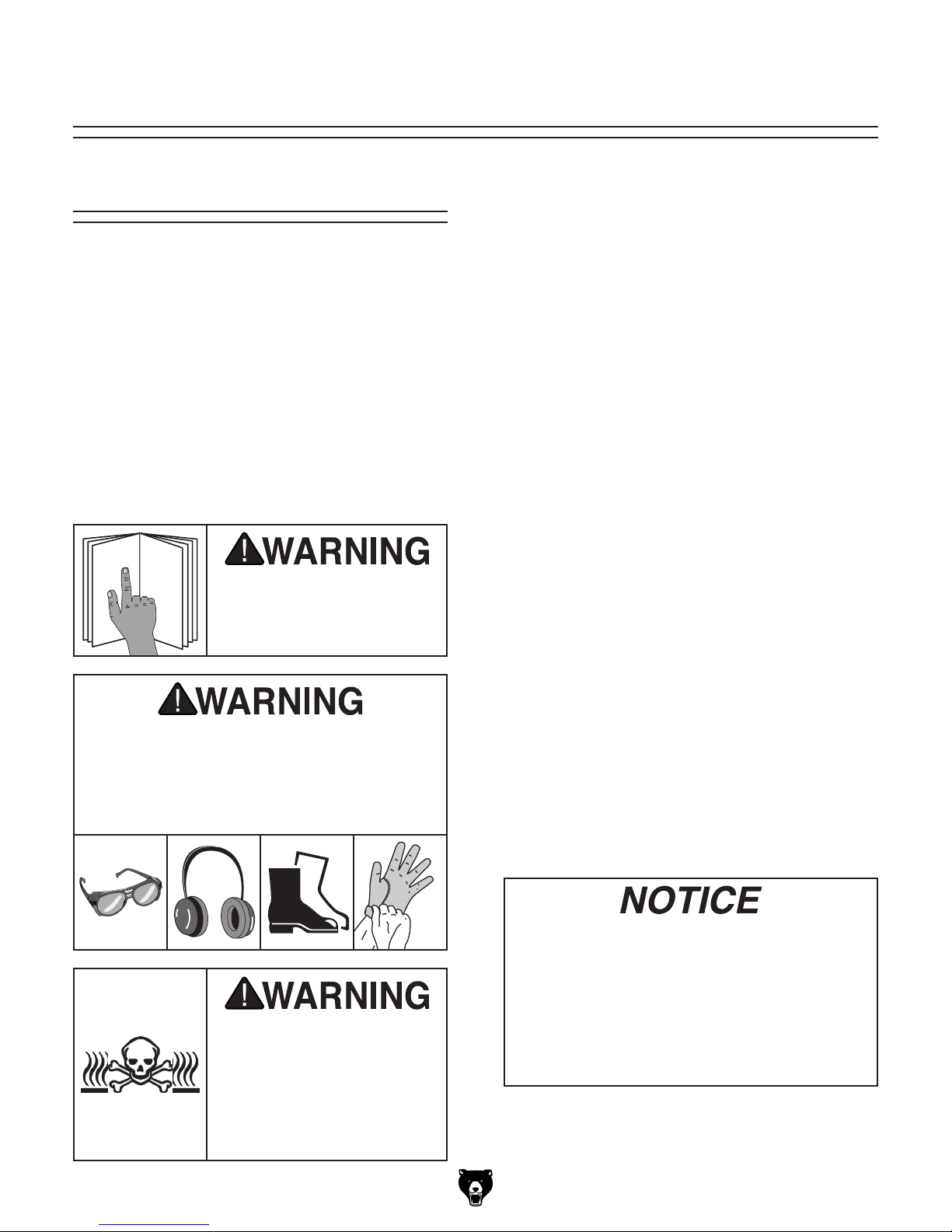
4. Turn engine ON/OFF switch to ON (I) position, as shown in Figure 26.
Engine ON/OFF Switch
Figure 26. Engine ON/OFF switch in ON
position.
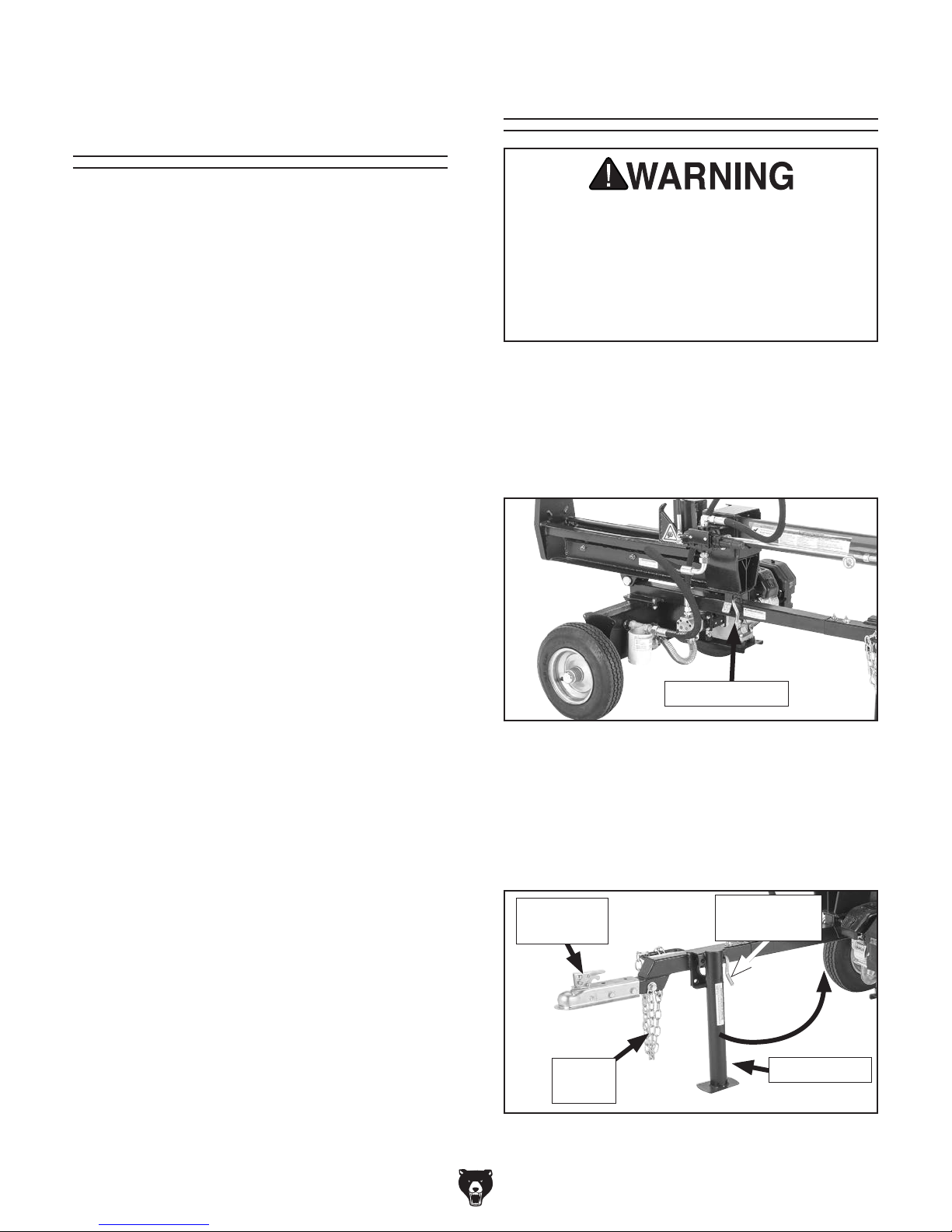
5. Move throttle control lever halfway between
SLOW (turtle) and FAST (rabbit), and move
choke lever to ON (I) position (see Figure 27).
Choke Lever
Throttle
Control Lever
Figure 27. Fuel shutoff lever and throttle lever
adjusted to starting positions.
-19 -
Page 22
Model T27710 (Mfd. Since 04/16)
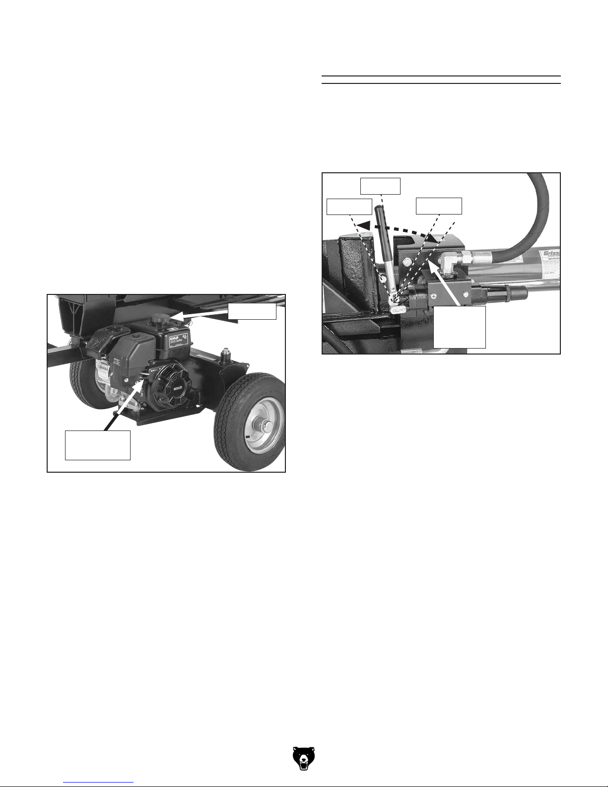
6. Pull starter handle (see Figure 28) slowly until resistance is felt. Retract handle,
then pull handle quickly with smooth, steady
motion until engine starts.
Starter Handle
Engine ON/OFF Switch
Figure 31. ON/OFF switch in OFF position.
Figure 28. Starter handle location.
7. After several seconds, move choke lever
slowly to OFF (O) position.
8. Let engine run at 75% throttle for one hour.
9. Move control lever (see Figure 29) to cycle
log splitter ram back and forth periodically
during break-in process to bleed hydraulic
system and check for fluid leaks. Do not
operate at full load until after engine break-in
has been completed.
Control Lever
11. After first 5 to 10 hours of initial operation,
change engine oil (refer to Kohler engine
manual for details).
If any problem or leak is found, do the following before you troubleshoot or correct
problem:
1. Shut engine down immediately and let it
cool for at least 15 minutes to prevent burn
injuries.
2. DISCONNECT SPARK PLUG WIRE (see
Figure 32) from spark plug to prevent
possibility of accidental start-up.
Spark Plug Wire
Figure 29. Control lever location.
10. To turn engine OFF, move throttle control
lever to SLOW (turtle), move ON/OFF switch
to OFF (O), and move fuel shutoff switch to
OFF (O), as shown in Figures 30–31.
Fuel Shutoff
Lever
Figure 30. Engine controls in OFF position.
-20-
Throttle
Control Lever
Figure 32. Location of spark plug.
IMPORTANT: If fluid leak is suspected or
seen, DO NOT touch area to find the leak.
Move control lever completely to forward and
backward positions to relieve any hydraulic
pressure and prevent possibility of hydraulic
fluid injection injury during repair.
3. Refer to Troubleshooting on Page 33 for
solutions, or call Technical Support at
(570) 546-9663.
Page 23
Model T27710 (Mfd. Since 04/16)
SECTION 3: OPERATIONS
To reduce your risk of
serious injury, read this
entire manual BEFORE
The purpose of this overview is to provide the novice machine operator with a basic understanding
of how the machine is used during operation, so
the
discussed later
in this manual
Due to the generic nature of this overview, it is
not intended to be an instructional guide. To learn
more about specific operations, read this entire
manual and
rienced
research outside of this manual by reading "howto" books, trade magazines, or websites.
Operation Overview
To complete a typical operation, the operator
does the following:
1. Places log splitter on flat, stable work
surface, and blocks wheels.
machine controls/components
are easier to understand.
seek additional training from expe-
machine operators, and do additional
using machine.
Bodily injury could result from using this
machine. Always wear safety glasses, hearing protection, leather work boots, and
heavy-duty leather work gloves when
operating this machine.
2. Makes sure support leg is secured in down
position.
3. Checks that engine and hydraulic tank are
filled with proper amount of fluid.
4. Sets up log splitter for horizontal or vertical
operation. If operating in horizontal position,
ensures beam is secured with beam lock pin;
if operating in vertical position, ensures foot
plate sits on flat, stable ground.
5. Puts on safety glasses, hearing protection,
leather work boots, and leather work gloves.
6. Turns engine ON.
7. Places log lengthwise on beam and flat
against foot plate.
8. Moves control lever to forward position to
drive wedge through log, then moves lever
to reverse position to retract wedge. After
wedge retracts, lever automatically resets to
neutral position.
9. Repeats Steps 4–8 as needed for remaining
logs, then turns engine OFF.
NEVER run engine indoors
such as in a garage, barn,
carport, or storage shed,
even if it is ventilated.
Engine exhaust is poisonous and can kill animals
and you without warning.
If you are not experienced with this type
of machine, WE STRONGLY RECOMMEND
that you seek additional training outside of
this manual. Read books/magazines or get
formal training before beginning any projects. Regardless of the content in this section, Grizzly Industrial will not be held liable
for accidents caused by lack of training.
-21-
Page 24
Model T27710 (Mfd. Since 04/16)
Considerations
TransportingJob Site
Work Location
Only use this log splitter outdoors, and never leave
the area while the engine is running. NEVER run
the engine indoors such as in a garage, barn,
carport, or storage shed, even if it is ventilated.
Engine exhaust is poisonous and can kill people
and animals without warning.
Always use the splitter on a flat, stable work surface, and block the log splitter wheels so it cannot
roll forward or backward.
Position the log splitter in a well lit, flat area at
least seven feet away from any dry leaves or combustibles, and at least 25 feet from any fresh air
intake supplying working or living areas.
Working Clearances
Allow enough room on all sides to move logs to
and from the splitter.
Keep your work zone clear of lumber to avoid tripping hazards while using the machine.
Log splitter is NOT designed to be towed on
logging roads, forest service roads, public
roads, or highways. It is designed for towing
only where maximum speed will not exceed
45 MPH. Log splitter must be transported
between job sites on trailer capable of
carrying 1000 lbs.
To tow splitter:
1. Lower log splitter cylinder and beam to hori-
zontal position, and lock with beam lock pin
(see Figure 33).
Beam Lock Pin
Figure 33. Beam lock pin location.
2. Raise and lock support leg in up position with
support-leg lock pin (see Figure 34).
3. Raise coupler lock lever (see Figure 34) to
unlatch it, and place coupler onto tow ball.
Coupler
Lock Lever
Safety
Chains
Figure 34. Raising support leg to towing
position.
Support-Leg
Lock Pin
Support Leg
-22-
Page 25
Model T27710 (Mfd. Since 04/16)
4. Make sure tow ball is fully seated inside
coupler.
Control Lever
5. Push down on coupler lock lever until it pulls
the lock tongue up against underside of tow
ball and locks tow ball and coupler together.
6. Secure safety chains (see Figure 34) to
tow vehicle and double-check all your
connections.
7. Close fuel shutoff valve (see Figure 35) on
engine carburetor to prevent fuel leakage.
8. Make sure engine gas cap (see Figure 35) is
secure and there are no tools or logs still on
log splitter. Never allow any riders or cargo
on log splitter while towing.
Gas Cap
When the engine is running and the control
lever is in the neutral position (see Figure 36),
the hydraulic pump delivers hydraulic fluid at 11
GPM through the control valve and back into the
hydraulic tank.
Neutral
Forward
Figure 36. Control lever positions.
Reverse
Locked in
Retract
Mode
Fuel Shutoff
Valve
Figure 35. Fuel shutoff valve and gas cap
location.
9. Tow log splitter responsibly! Do not tow it
while engine is operating, and take precautions to make sure machine will not
tip over during towing, causing a fuel leak
and possible fire.
When you move the control lever to the forward
position, the control valve diverts hydraulic fluid
up to 3600 PSI to one side of the splitter piston,
moving the splitting wedge into the log and splitting the log in half. The maximum distance of the
wedge stroke is 23
When you move the control lever to the full reverse
position, the lever locks in retract mode, and the
control valve diverts the hydraulic fluid to the other
side of the splitter piston. As a result, both of your
hands are free to load the next log for splitting.
When the ram fully retracts, the control lever
automatically moves back to neutral, and the log
splitter is ready to split another log.
1
⁄8".
-23-
Page 26
Model T27710 (Mfd. Since 04/16)
Splitting Logs
This log splitter is ONLY designed to split wood
with the direction of the grain. DO NOT attempt to
split or crush wood against the grain, or split brick,
concrete blocks, or rock. If you do, you will damage the machine, void the warranty, and possibly
severely injure or kill bystanders or yourself.
The log splitter can be operated in either the horizontal or vertical position, as shown in Figure 37.
The horizontal position is generally for lighter,
easy-to-lift logs; the vertical position is generally
for splitting heavier logs that are difficult to lift onto
the log splitter.
To operate log splitter:
1. Read and understand this entire manual and
Kohler engine manual.
Do NOT touch hydraulic cylinder or hydraulic tube during or immediately after operation. These components get extremely hot.
Allow them to cool before repositioning ram
and beam during following step.
4. Move beam and cylinder assembly to either
horizontal or vertical position (see Figure 37).
Horizontal Operation: Beam lock pin
automatically locks log splitter into position.
Pull up on beam to ensure splitter is locked.
Operator stands on side near control lever.
Vertical Operation: Pull beam lock pin out
and rotate beam and cylinder up until foot
plate sits squarely on level ground. Operator
stands in front of splitter on side by control
lever.
2. Verify your job site location meets at least
the minimum requirements for safety and
use. Refer to Job Site Considerations on
Page 22 for details.
3. Lower support leg and secure it in place with
support leg lock pin.
Horizontal Operation Vertical Operation
Control Lever
Beam
Splitting
Wedge
5. Closely inspect all components and hydraulic
lines for any evidence of damage, wear, or
unsafe conditions. Correct before proceeding
any further.
Beam
Assembly
Beam Lock
Pin
Work Zone is
Approximately a
6-Foot Sphere
Figure 37. Horizontal and vertical log splitter operating positions.
-24-
Foot Plate
Page 27
Model T27710 (Mfd. Since 04/16)
6. Put on safety glasses, hearing protection,
and thick leather gloves.
Removing
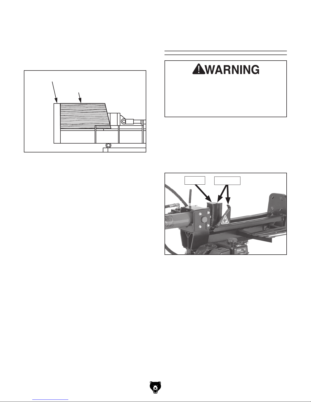
7. Start engine and place log lengthwise on
beam and flat against foot plate, as shown in
Figure 38.
Foot Plate
Log
Beam
Figure 38. Best placement of log against beam
and foot plate (horizontal operation shown).
8. Make sure bystanders are out of work zone
and that zone is clear of split logs. The work
zone is an approximate 6-foot sphere that
extends around log splitter, as shown in
Figure 37.
Stuck Logs
Never use your hands to remove a log stuck
on wedge, as it could crush hands and fingers during accidental startup. Always use
log dislodger to remove log. If log is still
stuck, turn log splitter OFF and use sledge
hammer and crow bar to remove stuck log.
This log splitter features a dislodger for helping
eject partially split logs or logs that get stuck on
the wedge. To eject a stuck log, move the control
lever to reverse until the split log contacts the dislodger brackets shown in Figure 39 and slips off
the wedge.
Wedge
Dislodger
9. While keeping hands clear of splitting wedge,
use control lever to split log, retract wedge,
and remove split log from work zone.
Figure 39. Dislodger location.
If the log remains stuck on the wedge, turn the
log splitter OFF and use a sledge hammer and
crowbar to remove the log.
-25-
Page 28
Model T27710 (Mfd. Since 04/16)
ACCESSORIES
Installing unapproved accessories may
order online at www.grizzly.com or call 1-800-523-4777
SECTION 4: ACCESSORIES
cause machine to malfunction, resulting in
serious personal injury or machine damage.
To reduce this risk, only install accessories
recommended for this machine by Grizzly.
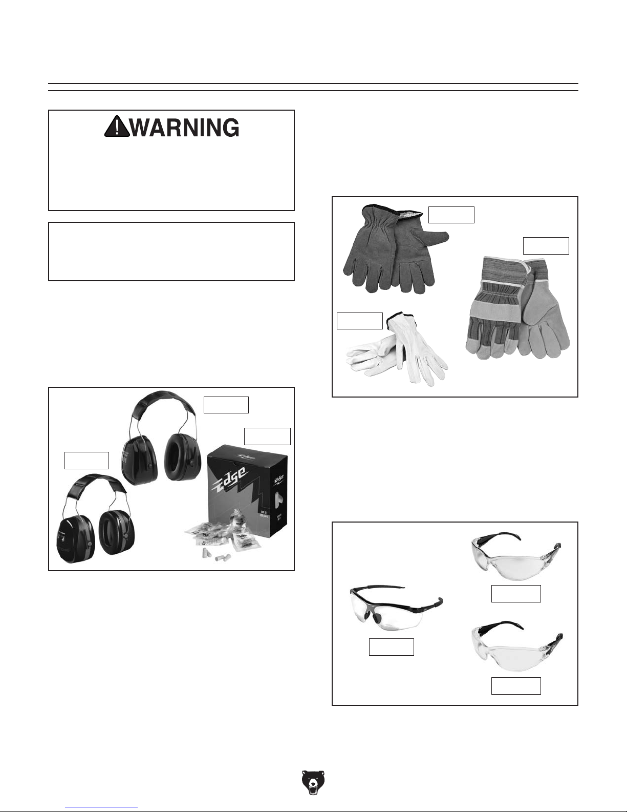
T21273—Golden Cowhide Gloves
T21272—Golden Pigskin Gloves
T20692—Deluxe Soft Goatskin Gloves
Grizzly offers a wide selection of synthetic and
leather gloves for all-day comfort in a variety of
working conditions.
T21273
NOTICE
Refer to our website or latest catalog for
additional recommended accessories.
H4978—Deluxe Earmuffs - 27dB
H4979—Twin Cup Hearing Protector - 29dB
T20446—Classic Earplugs, 200-pair - 31dB
Protect yourself comfortably with a pair of cushioned earmuffs. Especially important if you or
employees operate for hours at a time.
H4978
T20446
H4979
T21272
T20692
Figure 41. Assortment of gloves.
Basic Eye Protection
T20451—“Kirova” Clear Safety Glasses
T20452—“Kirova” Anti-Reflective S. Glasses
H7194—Bifocal Safety Glasses 1.5
H7195—Bifocal Safety Glasses 2.0
H7196—Bifocal Safety Glasses 2.5
Figure 40. Hearing protection.
H7194
Figure 42. Assortment of basic eye protection.
-26-
T20452
T20451
Page 29
Model T27710 (Mfd. Since 04/16)
order online at www.grizzly.com or call 1-800-523-4777
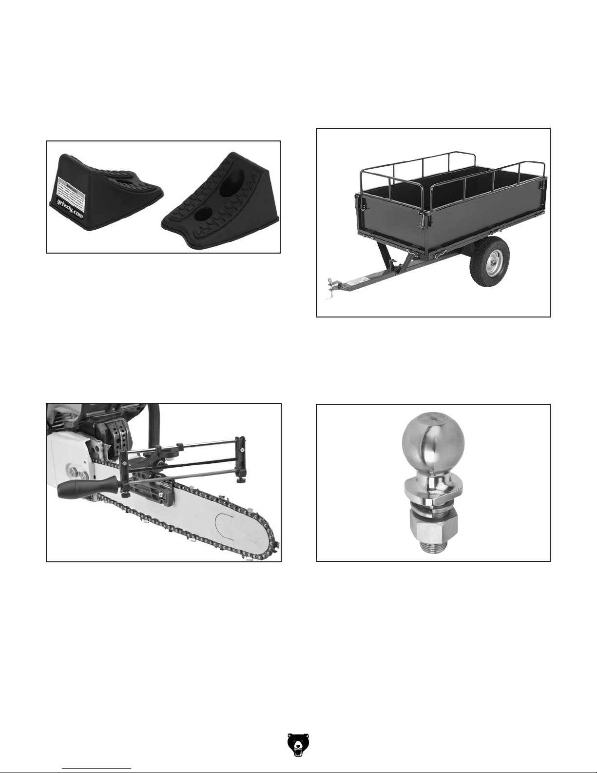
T10028—Pair of Wheel Chocks
Prevent accidental shifting of your vehicle with a
pair of these stackable, high impact plastic Wheel
Chocks. Just place each chock against the tires
and you know your vehicle isn’t going anywhere.
Great for campers and utility trailers as well as
preventing vehicles from shifting during jacking.
Figure 43. T10028 Pair of Wheel Chocks.
T10278—Chainsaw Filing Guide
Get the most out of your chainsaw with a properly
filed saw chain. This Chainsaw Filing Guide is
easy to use—requires no chain removal from the
saw. No guesswork involved—angle settings,
depths and file heights are dial set. Designed
to handle all saw chains. Accepts all chainsaw
file sizes (not included). Great for fast, on-site
sharpening!
T27709—17-Cubic-Foot Steel Dump Cart
This ruggedly constructed cart is perfect for hauling
logs. Features tilting dump bed with removable
rear panel for easy loading and unloading, and a
maximum capacity of 500 lbs. Dimensions:
1
59"L x 30
⁄2 "W x 231⁄2 "H.
Figure 45. T27709 Dump Cart.
H7824—2" Stainless Ball Hitch
This ball hitch has a 5,000-pound capacity and
includes nutsand lock washer. 2" hitch ball, 1" x
1
⁄4" shank.
2
Figure 44. T10278 Chainsaw Filing Guide.
Figure 46. H7824 2" Stainless Ball Hitch.
-27-
Page 30
Model T27710 (Mfd. Since 04/16)
SECTION 5: MAINTENANCE
Cleaning
To reduce risk of accidental start-up injury, disconnect spark plug wire before
performing adjustments or
maintenance.
For optimum performance from your log splitter,
clean it with a brush after every use and wipe it
down occasionally with a rag.
Schedule
For optimum performance from your machine,
follow this maintenance schedule and refer to any
specific instructions given in this section.
Daily Check:
• Hydraulic fluid and engine oil levels are full.
• Tires have recommended air pressure.
• Cracks, leaks, kinks, and abrasions do not
exist in hydraulic hoses, fuel lines, or fittings.
• Engine air filter is clean.
• Loose fasteners, hose clamps, bent
components.
• Safety features and guards are working and
in place.
Every 25 Hours of Use:
• Clean hydraulic tank vented cap (see
Page 29) with solvent, let air dry, re-install.
Lubrication
Items Needed Qty
Flat Head Screwdriver #2 .................................. 1
Pliers .................................................................. 1
Rubber Mallet .................................................... 1
Multi-Purpose Bearing Grease .......... As Needed
The wheel bearings will require lubrication with
multi-purpose bearing grease about every six
months.
To lubricate wheel bearings:
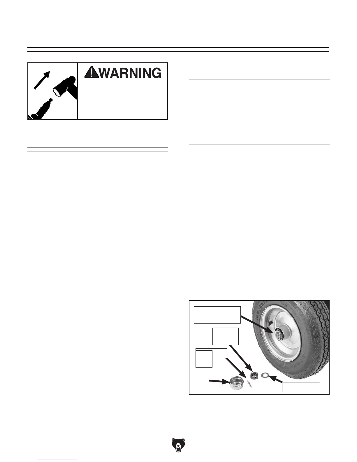
1. Remove wheel axle cap, cotter pin, flat washer,
and slotted hex nut shown in Figure 47.
2. Remove and clean inner and outer tapered
roller bearings (see Figure 47), re-pack these
with multi-purpose grease, and re-install.
Every 100 Hours of Use:
• Change hydraulic tank fluid, clean inner filter.
Every 500 Hours of Use:
• Change hydraulic tank filter (see Page 30).
Every 6 Months
• Relubricate wheel bushings (on this page).
As Needed:
• Inspect for burnt-smelling or tan-colored,
water-contaminated hydraulic fluid. If contaminated, replace tank vented cap, clean
tank filter/strainer, flush system, and replace
fluid.
• Refer to the Kohler engine manual for general engine maintenance schedules.
-28-
Tapered Roller
Bearing
Slotted
Hex Nut
Cotter Pin
Axle
Cap
Flat Washer
Figure 47. Components removed from wheel to
access and grease outer wheel bearing.
3. In reverse order, re-install wheel with components removed in Step 1.
Page 31

Model T27710 (Mfd. Since 04/16)
Checking/Adding
4. Re-install vented cap, remove it, then check
oil level on dipstick.
Hydraulic Fluid
Do not remove hydraulic vented cap while
engine is running or just after it is shut OFF.
You could be severely burned by hot vented
cap or hot hydraulic fluid escaping from
tank. Allow log splitter to cool sufficiently
before removing vented cap.
Items Needed Qty
Adjustable Wrench ............................................ 1
Clean Rag ......................................... As Needed
Drain Pan 5-Gallon ............................................ 1
Hydraulic Fluid AW-32, ASLE H-150, ISO 32 or
Universal Hydraulic Fluid ........... 3.5 Gallons
Flashlight ........................................................... 1
Checking Hydraulic Fluid Level
1. DISCONNECT SPARK PLUG WIRE!
2. Position log splitter on level ground, lower
support leg, and lock in place. Ensure engine
is cold.
— If fluid level is near middle of dipstick (see
Figure 49), no fluid needs to be added.
Proper Hydraulic
Oil Level
Figure 49. Location of correct hydraulic fluid
level on dipstick.
— If fluid level is below middle of dipstick,
add hydraulic fluid as required to bring it to
correct level. Refer to Adding Hydraulic
Fluid below.
— If fluid level is above middle of dipstick,
place drain pan under drain plug (see
Figure 48), and carefully remove plug
from bottom of hydraulic tank. Allow fluid to
drain to bring it to correct level. Re-install
drain plug when finished.
3. Remove vented cap (see Figure 48) and
wipe dipstick with clean rag.
Vented
cap
Drain Plug
Figure 48. Vented cap location.
5. Re-install vented cap.
6. Start engine. Use control lever to extend and
retract wedge several times to remove air
from hydraulic lines.
7. Turn engine OFF and repeat Step 1.
8. Repeat Steps 3–4 and continue adding
hydraulic fluid until level is correct.
Adding Hydraulic Fluid
1. DISCONNECT SPARK PLUG WIRE!
2. Remove vented cap (see Figure 48) and fill
hydraulic tank with 3.5 gallons of hydraulic
fluid or amount needed to fill tank to middle
of dipstick.
3. Check hydraulic fluid level (follow steps from
Checking Hydraulic Fluid Level) then re-
install vented cap.
-29-
Page 32

Model T27710 (Mfd. Since 04/16)
Changing Hydraulic
Fluid
4. Loosen filter cover hex bolts and carefully
dislodge cover slightly so hydraulic fluid spills
into drain pan (see Figure 50). Be careful to
avoid dropping rubber gasket into drain pan.
The hydraulic fluid should be inspected and
replaced on a regular basis. Replace the fluid
after every 100 hours of operation, if it smells
burnt, or if it is contaminated by water.
Water contamination can build up over time and
can be identified as a tan discoloration in the fluid.
Wear safety goggles when
servicing hydraulic system
to avoid getting hydraulic
fluid in your eyes.
Tools Needed Qty
Drain Pan 5-Gallon ............................................ 1
Disposable Shop Rags ...................... As Needed
Goggles ...................................1 Pair Per Person
Gloves ............................................ 1 Per Person
Hydraulic Fluid AW-32, ASLE H-150, ISO 32 or
Universal Hydraulic Fluid ........... 3.5 Gallons
Mineral Spirits ...................................... As Neeed
Open-End Wrench 10mm .................................. 1
5. When tank is empty, remove bolts all the
way, then remove suction filter.
6. Remove tank vented cap.
7. Clean tank vent with mineral spirits and let air
dry.
8. Clean suction filter screen with mineral spirits
and blow dry with compressed air.
9. Inspect suction filter screen and tank vent for
any holes, and replace if any damage exists.
10. Reach into tank and wipe out as much residual fluid and contaminants as possible. We
highly recommend tank be cleaned out with
a pressure washer or steam cleaner and fully
dried with compressed air for best results.
11. Re-install suction filter, rubber gasket, and
hose.
12. Fill tank with 3.5 gallons of hydraulic fluid and
re-install tank vented cap.
To change hydraulic fluid:
1. DISCONNECT SPARK PLUG WIRE!
2. Block log splitter wheels to prevent them from
rolling.
3. Place a 5-gallon drain pan under suction filter
cover, as shown in Figure 50.
Suction
Filter
Suction
Filter
Cover
Figure 50. Example photo of draining hydraulic
fluid.
13. Check hydraulic fluid level (refer to Page 29).
IMPORTANT: Be sure to dispose of old
hydraulic fluid according to federal, state, and
fluid manufacturer's requirements.
-30-
Page 33

Model T27710 (Mfd. Since 04/16)
StorageChanging Hydraulic
Tank Filter
The hydraulic tank filter shown in Figure 51
needs to be replaced every 500 operating hours,
but for convenience it should be done when you
change the hydraulic fluid (follow Steps 1–13 from
Changing Hydraulic Fluid on Page 30).
Hydraulic Tank
Filter
Figure 51. Location of hydraulic tank filter.
If the log splitter will not be used for longer than
two months, we recommend storing it. Be sure to
store the log splitter in a clean, dry, well-ventilated
area that is away from ignition sources and inaccessible to children.
Preparing Log Splitter for Storage
1. Wait for engine to cool, and clean log splitter
thoroughly with a clean, dry cloth. Do not use
water to clean log splitter, as it could damage
bearings or the engine.
2. Use lightly oiled rag to wipe down all metal
components to prevent rust.
3. Follow Kohler engine manual instructions for
preparing engine for storage.
Bringing Log Splitter Out of Storage
1. Follow Kohler engine manual instructions for
storage in reverse.
The hydraulic tank filter can be purchased from
most local hardware stores, or replacement part
#PT27710040 can be purchased by contacting
the Grizzly Order Desk at (800) 523-4777.
To change the filter, DISCONNECT SPARK PLUG
WIRE!, drain the hydraulic tank, remove the old
filter, and install the new one. Be sure to follow
any additional instructions the replacement filter
manufacturer provides.
IMPORTANT: Be sure to dispose of old hydraulic
fluid according to federal, state, and fluid manufacturer's requirements.
2. Drain fuel from tank and use clean, fresh,
unleaded gasoline that meets Kohler's specifications, especially if fuel has been sitting
for longer than fuel stabilizer manufacturer's
recommendation.
3. Perform Test Run/Break In procedure on
Page 19 before putting log splitter back into
service.
-31-
Page 34

Model T27710 (Mfd. Since 04/16)
Sharpening Splitting
Wedge
To reduce risk of serious
cuts, always wear leather
gloves when sharpening
splitting wedge.
During the life of your log splitter, you will need
to sharpen the splitting wedge periodically. When
sharpening the wedge, keep in mind that if you try
to keep the wedge sharpened to a razor point (like
an axe blade), you will greatly reduce the life of the
wedge by always sharpening it. However, if you
allow the point to become very dull or bullnosed,
your log splitter will have to overwork to split logs,
which will decrease the lifespan of the splitter. The
optimum point is somewhere between. Refer to
Figure 52 for a general idea.
Wedge Too Sharp
Wedge Too Dull
Wedge Just Right
Figure 52. Good and bad wedge points.
-32-
Page 35

Model T27710 (Mfd. Since 04/16)
Review the troubleshooting and procedures in this section if a problem develops with your machine. If
you need replacement parts or additional help with a procedure, call our Technical Support.
gather the serial number and manufacture date of your machine before calling.
SECTION 6: SERVICE
Troubleshooting
Operation
Symptom Possible Cause Possible Solution
Splitting wedge
moves forward
and backward too
slowly, or does
not move in either
direction.
Splitting wedge
moves forward
too slowly or not
at all, but retracts
correctly.
Splitting wedge
retracts too slowly
or not at all, but
moves forward
correctly.
Splitter will not split
wood or splits it too
slowly.
Hydraulic tank fluid
burnt or has tan
discoloration.
1. Hydraulic tank empty or low.
2. Tank suction filter clogged.
3. Air in hydraulic system.
4. Control lever linkage at fault.
5. Pump or pump relief valve at fault.
6. Hydraulic control valve at fault.
7. Damaged ram piston seals.
1. Control lever linkage at fault.
2. Splitting wedge dull; log unsuitable for
splitting.
3. Hydraulic fluid too low or contaminated.
4. Hydraulic control valve at fault.
5. Damaged ram piston seals.
1. Control lever linkage at fault.
2. Hydraulic control valve at fault.
3. Damaged ram piston seals.
1. Splitting wedge dull.
2. Engine oil level too low or contaminated.
3. Hydraulic tank filter clogged.
4. Splitting wood against grain.
5. Air in hydraulic system.
1. Hydraulic fluid old or contaminated with
water.
1. Fill tank to required level (Page 29).
2. Clean suction filter (Page 30). Service hydraulic
system.
3. Bleed air out of system by moving wedge back/forth
several times until it moves smoothly.
4. Replace/repair bent or worn linkage to provide full
range of travel.
5. Replace pump and flush/service hydraulic system
(Page 30).
6. Replace valve and flush/service hydraulic system
(Page 30).
7. Replace ram assembly and flush/service hydraulic
system (Page 30).
1. Replace/repair bent or worn linkage to provide full
range of travel.
2. Sharpen wedge; avoid splitting logs with twisted
grain, numerous knots, or high moisture content.
3. Replace/fill tank to required fluid level (Page 29).
4. Replace valve and flush/service hydraulic system
(Page 30).
5. Replace ram assembly and flush/service hydraulic
system (Page 30).
1. Replace/repair bent or worn linkage to provide full
range of travel.
2. Replace control valve.
3. Replace ram assembly and flush/service hydraulic
system (Page 30).
1. Sharpen wedge (Page 32).
2. Add/replace engine oil.
3. Replace hydraulic tank filter (Page 31).
4. Split wood with grain instead of against grain.
5. Bleed air out of hydraulic system.
1. Replace hydraulic fluid (Page 30).
Note: Please
Note: Refer to the Kohler engine manual for engine-related troubleshooting.
-33-
Page 36

Model T27710 (Mfd. Since 04/16)
SECTION 7: HYDRAULIC SYSTEM
Fluid
Tank
Control
Valve
Ram
Engine
Pump
Filter
Figure 53. Hydraulic system components.
Ram
Before servicing hydraulic parts,
stop engine and depressurize
entire hydraulic system by moving
control lever back and forth a few
times. Ignoring this warning may
lead to hydraulic fluid poisoning,
which is a serious and potentially
fatal injury.
Control
Valve
Engine
Pump
DEW HYD-8.8/2.15
1H513109
Suction Filter
Hydraulic Fluid Reservoir
This diagram is only provided as a reference to help you identify hydraulic system components. Seek assistance from a
professional hydraulic technician whenever
servicing or repairing the hydraulic system.
Filter
20 GPM
200 PSI
1–12 UNF
-34-
Page 37

Model T27710 (Mfd. Since 04/16)
39
We do our best to stock replacement parts when possible, but we cannot guarantee that all parts shown
are available for purchase. Call (800) 523-4777 or visit www.grizzly.com/parts to check for availability.
SECTION 8: PARTS
Main
B
23
72
22
54
51
32
15
9
21
14
13
3
45
46
49
20
47
18
20
16
41
17
5
7
19
8
5
20
74
2
22
42
56
47
25
48
73
20
25
6
33
33
16
B
31
75
61
60
65
A
66
69
57
37
6
8
64
63
57
38
37
57
5
7
38
67
68
11
58
12
10
32
25
59
44
1
4
52
4
35
62
29
44
70
27
26
55
40
A
19
30
28
43
18
41
20
5
24
71
50
34
20
25
53
36
-35-
Page 38

Model T27710 (Mfd. Since 04/16)
Main Parts List
REF PART # DESCRIPTION REF PART # DESCRIPTION
1 PT27710001 HYDRAULIC FLUID TANK 39 PT27710039 HYDRAULIC HOSE 602-1302 62"L
2 PT27710002 TONGUE SECTION (FRONT) 40 PT27710040 FILTER 20GPM 200PSI 5.4" 1-12UNF 10-30M
3 PT27710003 BEAM 41 PT27710041 CONNECTOR-MM M26-1.75, M26-1.75
4 PT27710004 WHEEL W/TIRE 8 X 3.75, 4.80-8 42 PT27710042 HYDRAULIC HOSE 602-1302 48"L
5 PT27710005 COTTER PIN 4 X 36 STANDARD 43 PT27710043 HYDRAULIC HOSE 1-3/8" X 18" (CLEAR)
6 PT27710006 FLAT WASHER 20MM 44 PT27710044 HOSE CLAMP 1-1/2"
7 PT27710007 AXLE CAP 45 PT27710045 HEX BOLT M12-1.75 X 90
8 PT27710008 HEX NUT THIN SLOTTED M20-2.5 46 PT27710046 HEX BOLT M12-1.75 X 80
9 PT27710009 CYLINDER COVER 47 PT27710047 FENDER WASHER 12MM
10 PT27710010 WEDGE SLIDE 48 PT27710048 SAFETY CHAIN W/HOOK 28-LINK
11 PT27710011 ENGINE KOHLER 3000 6.5HP 196CC 49 PT27710049 BALL RECEIVER 2"
12 PT27710012 RUBBER SHOCK ABSORBER 50 PT27710050 CLEVIS PIN 21 X 126
13 PT27710013 O-RING 16 X 2.5 51 PT27710051 CONTROL VALVE COVER
14 PT27710014 CONNECTOR-MF M22-1.75, M28-1.25 52 PT27710052 HYDRAULIC CYLINDER ASSEMBLY
15 PT27710015 CONTROL VALVE ASSEMBLY 53 PT27710053 DRAIN PLUG 3/8 NPT
16 PT27710016 ELBOW-MM 90DEG M22-1.75, M22-1.75 54 PT27710054 PHLP HD SCR M8-1.25 X 10
17 PT27710017 HYDRAULIC TUBE 16 OD X 560 L (SS) 55 PT27710055 SUPPORT LEG
18 PT27710018 SAFETY PIN 56 PT27710056 EXT RETAINING RING 62MM
19 PT27710019 COMPRESSION SPRING 1.5 X 18 X 60 57 PT27710057 LOCK WASHER 8MM
20 PT27710020 FLAT WASHER 12MM 58 PT27710058 FENDER WASHER 8MM
21 PT27710021 ELBOW-MM 90DEG M22-1.75, M26-1.75 59 PT27710059 PUMP DELI CBNA-8.8/2.1J
22 PT27710022 FLAT WASHER 10MM 60 PT27710060 HEX BOLT M8-1.25 X 30
23 PT27710023 HEX BOLT M10-1.5 X 20 61 PT27710061 EXT RETAINING RING 11MM
24 PT27710024 HEX BOLT M12-1.75 X 65 62 PT27710062 TONGUE SECTION (REAR)
25 PT27710025 LOCK NUT M12-1.75 63 PT27710063 PUMP COUPLER
26 PT27710026 FILTER MOUNT PLATE 64 PT27710064 ENGINE COUPLER
27 PT27710027 GASKET (RUBBER) 65 PT27710065 ENGINE COUPLER BUSHING
28 PT27710028 FLAT WASHER 6MM 66 PT27710066 PUMP MOUNTING BLOCK
29 PT27710029 LOCK WASHER 6MM 67 PT27710067 HEX BOLT M5-.8 X 10
30 PT27710030 HEX BOLT M6-1 X 20 68 PT27710068 COUPLER COVER
31 PT27710031 PUMP CONNECTOR M26-1.75 69 PT27710069 HEX BOLT M8-1.25 X 25
32 PT27710032 O-RING 11.2 X 2.4 70 PT27710070 INNER FILTER
33 PT27710033 O-RING 17 X 2.5 71 PT27710071 COTTER PIN 1-3/4–1-7/8 X 2-1/2 HAIRPIN
34 PT27710034 VENTED CAP 1-1/4 NPT 72 PT27710072 LOCK WASHER 10MM
35 PT27710035 HEX BOLT M12-1.75 X 35 73 PT27710073 HEX BOLT M10-1.5 X 70
36 PT27710036 HEX BOLT M8-1.25 X 65 74 PT27710074 LOCK NUT M10-1.5
37 PT27710037 FLAT WASHER 8MM 75 PT27710075 SET SCREW M6-1 X 10
38 PT27710038 LOCK NUT M8-1.25
-36-
Page 39

Model T27710 (Mfd. Since 04/16)
101
111
WARNING!
To reduce risk of death
or serious injury, read
manual BEFORE using
machine.
To get a new manual,
call (800) 523-4777 or
go to www.grizzly.com.
WARNING!
AMPUTATION
HAZARD!
Keep hands and arms
away from this splitting
head when splitting
logs.
102
EYE INJURY
HAZARD!
Always wear safety
glasses when using
this machine.
104
DO NOT touch hydraulic
cylinder during operation.
Cylinder gets extremely
hot. Allow cylinder to cool
before touching.
WARNING!
BURN HAZARD!
Labels
103
Specifications
Engine: Kohler 3000, 6.5 HP, 196 CC
Splitting Force: 22 Tons
Hydraulic Oil Capacity: 3.5 Gallons
Hydraulic Pressure: 3600 PSI Max.
Maximum Log Length: 25-5/8"
Hydraulic Cyl. Bore/Stroke: 4" x 23-1/8"
Tow Ball Diameter: 2"
Weight: 388 lbs.
Date
S/N
Mfd. for Grizzly in China
WARNING!
BURN HAZARD!
DO NOT touch hydraulic
106
cylinder during operation.
Cylinder gets extremely
hot. Allow cylinder to cool
before touching.
104
WARNING!
Support leg MUST be locked
in horizontal position (with
safety pin engaged) when
towing/transporting log
splitter. Failure to do this
could cause serious injury
from loss of vehicle control
or severe property damage.
107
22-TON HYDRAULIC LOG SPLITTER
1. Read and understand manual and engine manual before
using.
2. Always wear ANSI approved safety glasses and hearing
protection.
3. Never place hands on log or splitter wedge during operation.
4. Make sure no fuel spills or leaks exist before starting engine.
5. Do not force log splitter beyond 22-ton capacity.
6. Never leave log splitter with a log under pressure.
7. Keep all combustibles away from engine exhaust port.
8. Never leave log splitter running unattended.
9. Always stop engine before refueling or clearing a jam.
MODEL T27710
WARNING!
:enihcam siht gnisu nehw yrujni lanosrep suoires fo ksir ecuder oT
10. Never operate log splitter engine in enclosed or
non-ventilated areas. Carbon monoxide from engine exhaust
is poisonous and odorless, and can kill without warning.
11. Do not tow log splitter on public roads or highway! It is only
designed for backyard towing at speeds no greater than 45
MPH.
12. Tie back long hair and clothing, and remove all jewelry or
other loose apparel to avoid entanglement.
13. Do not operate under influence of drugs or alcohol, or if tired.
14. Prevent unauthorized use by children or untrained users;
restrict access or disable machine when unattended.
105
WARNING!
108
110
CHECK
HYDRAULIC FLUID/
ENGINE OIL LEVEL
BEFORE USING!
REFER TO
OWNER’S MANUAL
FOR FLUID/OIL TYPE
AND AMOUNT.
WARNING!
Beam MUST be locked in horizontal
position (with safety pin engaged)
when towing/transporting log splitter.
Failure to do this could cause serious
injury from loss of vehicle control or
severe property damage.
109
TOWING HAZARD!
Do not tow this log
splitter on highways
or public roads.
It is designed for
repositioning at the
jobsite only. Never
exceed 45 MPH.
REF PART # DESCRIPTION REF PART # DESCRIPTION
101 PT27710101 AMPUTATION HAZARD LABEL 107 PT27710107 MACHINE ID LABEL
102 PT27710102 EYE INJURY HAZARD LABEL 108 PT27710108 TOWING HAZARD LABEL
103 PT27710103 TOUCH-UP PAINT, GRIZZLY GREEN 109 PT27710109 BEAM SAFETY PIN WARNING LABEL
104 PT27710104 BURN HAZARD LABEL 110 PT27710110 STOP CHECK FLUID/OIL TAG
105 PT27710105 TOUCH-UP PAINT, GLOSSY BLACK 111 PT27710111 READ MANUAL LABEL
106 PT27710106 SUPPORT LEG WARNING LABEL
Safety labels help reduce the risk of serious injury caused by machine hazards. If any label comes
off or becomes unreadable, the owner of this machine MUST replace it in the original location
before resuming operations. For replacements, contact (800) 523-4777 or www.grizzly.com.
-37-
Page 40

-38-
Model T27710 (Mfd. Since 04/16)
Page 41

WARRANTY CARD
Name _____________________________________________________________________________
Street _____________________________________________________________________________
City _______________________ State _________________________ Zip _____________________
Phone # ____________________ Email _________________________________________________
Model # ____________________ Order # _______________________ Serial # __________________
The following information is given on a voluntary basis. It will be used for marketing purposes to help us develop
better products and services. Of course, all information is strictly confidential.
1. How did you learn about us?
____ Advertisement ____ Friend ____ Catalog
____ Card Deck ____ Website ____ Other:
2. Which of the following magazines do you subscribe to?
____ Cabinetmaker & FDM
____ Family Handyman
____ Hand Loader
____ Handy
____ Home Shop Machinist
____ Journal of Light Cont.
____ Live Steam
____ Model Airplane News
____ Old House Journal
____ Popular Mechanics
3. What is your annual household income?
____ $20,000-$29,000 ____ $30,000-$39,000 ____ $40,000-$49,000
____ $50,000-$59,000 ____ $60,000-$69,000 ____ $70,000+
CUT ALONG DOTTED LINE
4. What is your age group?
____ 20-29 ____ 30-39 ____ 40-49
____ 50-59 ____ 60-69 ____ 70+
5. How long have you been a woodworker/metalworker?
____ 0-2 Years ____ 2-8 Years ____ 8-20 Years ____20+ Years
6. How many of your machines or tools are Grizzly?
____ 0-2 ____ 3-5 ____ 6-9 ____10+
____ Popular Science
____ Popular Woodworking
____ Precision Shooter
____ Projects in Metal
____ RC Modeler
____ Rie
____ Shop Notes
____ Shotgun News
____ Today’s Homeowner
____ Wood
____ Wooden Boat
____ Woodshop News
____ Woodsmith
____ Woodwork
____ Woodworker West
____ Woodworker’s Journal
____ Other:
7. Do you think your machine represents a good value? _____ Yes _____No
8. Would you recommend Grizzly Industrial to a friend? _____Yes _____No
9. Would you allow us to use your name as a reference for Grizzly customers in your area?
Note: We never use names more than 3 times. _____Yes _____No
10. Comments: _____________________________________________________________________
_________________________________________________________________________________
_________________________________________________________________________________
_________________________________________________________________________________
Page 42

FOLD ALONG DOTTED LINE
FOLD ALONG DOTTED LINE
Place
Stamp
Here
GRIZZLY INDUSTRIAL, INC.
P.O. BOX 2069
BELLINGHAM, WA 98227-2069
Send a Grizzly Catalog to a friend:
Name_______________________________
Street_______________________________
City______________State______Zip______
TAPE ALONG EDGES--PLEASE DO NOT STAPLE
Page 43

WARRANTY & RETURNS
Grizzly Industrial, Inc. warrants every product it sells for a period of 1 year to the original purchaser from
the date of purchase. This warranty does not apply to defects due directly or indirectly to misuse, abuse,
negligence, accidents, repairs or alterations or lack of maintenance. This is Grizzly’s sole written warranty
and any and all warranties that may be implied by law, including any merchantability or fitness, for any particular purpose, are hereby limited to the duration of this written warranty. We do not warrant or represent
that the merchandise complies with the provisions of any law or acts unless the manufacturer so warrants.
In no event shall Grizzly’s liability under this warranty exceed the purchase price paid for the product and
any legal actions brought against Grizzly shall be tried in the State of Washington, County of Whatcom.
We shall in no event be liable for death, injuries to persons or property or for incidental, contingent, special,
or consequential damages arising from the use of our products.
To take advantage of this warranty, contact us by mail or phone and give us all the details. We will then issue
you a “Return Number,’’ which must be clearly posted on the outside as well as the inside of the carton. We
will not accept any item back without this number. Proof of purchase must accompany the merchandise.
The manufacturers reserve the right to change specifications at any time because they constantly strive to
achieve better quality equipment. We make every effort to ensure that our products meet high quality and
durability standards and we hope you never need to use this warranty.
Please feel free to write or call us if you have any questions about the machine or the manual.
Thank you again for your business and continued support. We hope to serve you again soon.
Page 44

Page 45

Page 46

Page 47

Page 48

Page 49

Page 50

Page 51

Page 52

Page 53

Page 54

Page 55

Page 56

Page 57

Page 58

Page 59

Page 60

Page 61

Page 62

Page 63

SH265
Service Manual
IMPORTANT: Read all safety precautions and instructions carefully before operating equipment. Refer to operating
instruction of equipment that this engine powers.
Ensure engine is stopped and level before performing any maintenance or service.
2 Safety
3 Maintenance
5 Specifi cations
12 Tools and Aids
15 Troubleshooting
19 Air Cleaner/Intake
20 Fuel System
24 Governor System
25 Lubrication System
26 Electrical System
30 Starter System
33 Disassembly/Inspection and Service
43 Reassembly
18 690 01 Rev. C KohlerEngines.com
1
Page 64

Safety
SAFETY PRECAUTIONS
WARNING: A hazard that could result in death, serious injury, or substantial property damage.
CAUTION: A hazard that could result in minor personal injury or property damage.
NOTE: is used to notify people of important installation, operation, or maintenance information.
WARNING
Explosive Fuel can cause
fi res and severe burns.
Do not fi ll fuel tank while
engine is hot or running.
Gasoline is extremely fl ammable
and its vapors can explode if
ignited. Store gasoline only in
approved containers, in well
ventilated, unoccupied buildings,
away from sparks or fl ames.
Spilled fuel could ignite if it comes
in contact with hot parts or sparks
from ignition. Never use gasoline
as a cleaning agent.
WARNING
Rotating Parts can cause
severe injury.
Stay away while engine
is in operation.
Keep hands, feet, hair, and
clothing away from all moving
parts to prevent injury. Never
operate engine with covers,
shrouds, or guards removed.
WARNING
Carbon Monoxide can
cause severe nausea,
fainting or death.
Avoid inhaling exhaust
fumes.
Engine exhaust gases contain
poisonous carbon monoxide.
Carbon monoxide is odorless,
colorless, and can cause death if
inhaled.
Accidental Starts can
cause severe injury or
death.
Disconnect and ground
spark plug lead(s) before
servicing.
Before working on engine or
equipment, disable engine as
follows: 1) Disconnect spark plug
lead(s). 2) Disconnect negative (–)
battery cable from battery.
Hot Parts can cause
severe burns.
Do not touch engine
while operating or just
after stopping.
Never operate engine with heat
shields or guards removed.
Cleaning Solvents can
cause severe injury or
death.
Use only in well
ventilated areas away
from ignition sources.
Carburetor cleaners and solvents
are extremely fl ammable. Follow
cleaner manufacturer’s warnings
and instructions on its proper and
safe use. Never use gasoline as a
cleaning agent.
WARNING
WARNING
WARNING
Electrical Shock can
cause injury.
Do not touch wires while
engine is running.
Damaging Crankshaft
and Flywheel can cause
personal injury.
Using improper procedures can
lead to broken fragments. Broken
fragments could be thrown from
engine. Always observe and use
precautions and procedures when
installing fl ywheel.
Uncoiling Spring can
cause severe injury.
Wear safety goggles or
face protection when
servicing retractable
starter.
Retractable starters contain a
powerful, recoil spring that is
under tension. Always wear safety
goggles when servicing retractable
starters and carefully follow
instructions in Retractable Starter
for relieving spring tension.
CAUTION
CAUTION
WARNING
2
KohlerEngines.com 18 690 01 Rev. C
Page 65

Maintenance
MAINTENANCE INSTRUCTIONS
WARNING
Accidental Starts can cause severe injury or
death.
Disconnect and ground spark plug lead(s)
before servicing.
Normal maintenance, replacement or repair of emission control devices and systems may be performed by any repair
establishment or individual; however, warranty repairs must be performed by a Kohler authorized dealer.
MAINTENANCE SCHEDULE
After fi rst 5 Hours
● Change oil. Lubrication System
Every 50 Hours or Annually
● Service/replace dual-element precleaner. Air Cleaner/Intake
Every 100 Hours or Annually¹
● Clean low-profi le air cleaner element. Air Cleaner/Intake
● Replace dual-element air cleaner element. Air Cleaner/Intake
● Change oil. Lubrication System
● Clean cooling areas. Air Cleaner/Intake
● Clean spark arrestor (if equipped).
● Replace fuel fi lter (if equipped).
Before working on engine or equipment, disable engine as
follows: 1) Disconnect spark plug lead(s). 2) Disconnect
negative (–) battery cable from battery.
Every 100 Hours
2
● Check and adjust valve clearance when engine is cold. Reassembly
● Have combustion chamber decarbonized.
Every 125 Hours or Annually¹
● Replace spark plug and set gap. Electrical System
Every 200 Hours²
● Replace fuel line. Fuel System
Every 300 Hours
● Replace low-profi le air cleaner element. Air Cleaner/Intake
1
Perform these procedures more frequently under severe, dusty, dirty conditions.
2
Have a Kohler authorized dealer perform this service.
REPAIRS/SERVICE PARTS
Kohler genuine service parts can be purchased from Kohler authorized dealers. To fi nd a local Kohler authorized
dealer visit KohlerEngines.com or call 1-800-544-2444 (U.S. and Canada).
18 690 01 Rev. C KohlerEngines.com
3
Page 66

Maintenance
OIL RECOMMENDATIONS
We recommend use of Kohler oils for best performance.
Other high-quality detergent oils (including synthetic)
of API (American Petroleum Institute) service class SJ
or higher are acceptable. Select viscosity based on
air temperature at time of operation as shown in table
below.
FUEL RECOMMENDATIONS
WARNING
Explosive Fuel can cause fi res and severe
burns.
Do not fi ll fuel tank while engine is hot or
running.
STORAGE
If engine will be out of service for 2 months or more
follow procedure below.
1. Add Kohler PRO Series fuel treatment or equivalent
to fuel tank. Run engine 2-3 minutes to get stabilized
fuel into fuel system (failures due to untreated fuel
are not warrantable).
2. Change oil while engine is still warm from operation.
Remove spark plug(s) and pour about 1 oz. of
engine oil into cylinder(s). Replace spark plug(s) and
crank engine slowly to distribute oil.
3. Disconnect negative (-) battery cable.
4. Store engine in a clean, dry place.
Gasoline is extremely fl ammable and its vapors can
explode if ignited. Store gasoline only in approved
containers, in well ventilated, unoccupied buildings,
away from sparks or fl ames. Spilled fuel could ignite
if it comes in contact with hot parts or sparks from
ignition. Never use gasoline as a cleaning agent.
NOTE: E15, E20 and E85 are NOT approved and
should NOT be used; effects of old, stale or
contaminated fuel are not warrantable.
Fuel must meet these requirements:
● Clean, fresh, unleaded gasoline.
● Octane rating of 87 (R+M)/2 or higher.
● Research Octane Number (RON) 90 octane minimum.
● Gasoline up to 10% ethyl alcohol, 90% unleaded is
acceptable.
● Methyl Tertiary Butyl Ether (MTBE) and unleaded
gasoline blend (max 15% MTBE by volume) are
approved.
● Do not add oil to gasoline.
● Do not overfi ll fuel tank.
● Do not use gasoline older than 30 days.
4
KohlerEngines.com 18 690 01 Rev. C
Page 67

Engine Dimensions
Dimensions in millimeters.
Inch equivalents shown in [ ].
273.97
[10.786]
369.40
[14.543]
Specifi cations
318.66
[12.545]
STRAIGHT PTO
181.60
[7.150]
113.44
[4.466]
SPARK
PLUG
OIL FILL
DRAIN PLUG
342.20
[13.473]
65.05
[2.561]
32.53 [1.281]
32.53
[1.281]
66.00 [2.598]
65.05 [2.561]
88.00
[3.465]
162.00
[6.378]
110.00 [4.331]
AIR CLEANER
COVER
REMOVAL
339.90
[13.382]
30.00
[1.181]
106.00
[4.173]
METRIC FLANGE: 4X M8 X 1.25-6H
SAE A FLANGE: 4X 5/16-24 UNF-2B THRU
METRIC FLANGE: 4X M8 X 1.25-6H
SAE A FLANGE: 4X
5/16-24 UNF-2B 15.00 [0.591]
37.98 [1.495]
37.50 [1.476]
THRU
15.00 [0.591]
78.00
[3.071]
2X Ø 10.00 [0.394]
2X 10.00 X 15.50
SLOT [0.394 X 0.610]
12.50
[0.492]
GAS CAP
REMOVAL
18 690 01 Rev. C KohlerEngines.com
5
Page 68

Specifi cations
ENGINE IDENTIFICATION NUMBERS
Kohler engine identifi cation numbers (model, specifi cation and serial) should be referenced for effi cient repair,
ordering correct parts, and engine replacement.
Model . . . . . . . . . . . . . . . . . . . . . SH265
Courage Engine
Horizontal Shaft
Numerical Designation
Specifi cation . . . . . . . . . . . . . . . SH265-0001
Serial . . . . . . . . . . . . . . . . . . . . . 4323500328
Year Manufactured Code Factory Code
Code Year
43 2013
44 2014
45 2015
GENERAL SPECIFICATIONS
3,6
SH265
Bore 68 mm (2.7 in.)
Stroke 54 mm (2.1 in.)
Displacement 196 cc (12.0 cu. in.)
Oil Capacity (refi ll) 0.6 L (0.63 U.S. qt.)
Maximum Angle of Operation (@ full oil level)
TORQUE SPECIFICATIONS
3,5
4
25°
SH265
Air Cleaner
Mounting Screw (into intake manifold) 8 N·m (70.8 in. lb.)
Blower Housing and Sheet Metal
M6 Shoulder Screw 10 N·m (88.5 in. lb.)
M6 Nut 8 N·m (70.8 in. lb.)
Carburetor
Stud 10 N·m (88.5 in. lb.)
Primary Nut 8 N·m (70.8 in. lb.)
Secondary Nut 10 N·m (88.5 in. lb.)
Intake Cover Nut 4 N·m (35.4 in. lb.)
Connecting Rod
Cap Fastener (torque in increments) 12 N·m (106 in. lb.)
Crankcase
Oil Drain Plug 18 N·m (13 ft. lb.)
Closure Plate Screw 24 N·m (212 in. lb.)
Cylinder Head
Fastener (torque in 2 increments) fi rst to 12 N·m (106 in. lb.)
3
Values are in Metric units. Values in parentheses are English equivalents.
4
Exceeding maximum angle of operation may cause engine damage from insuffi cient lubrication.
5
Lubricate threads with engine oil prior to assembly.
6
Any and all horsepower (hp) references by Kohler are Certifi ed Power Ratings and per SAE J1940 & J1995 hp
standards. Details on Certifi ed Power Ratings can be found at KohlerEngines.com.
6
fi nally to 24 N·m (212 in. lb.)
KohlerEngines.com 18 690 01 Rev. C
Page 69

Specifi cations
TORQUE SPECIFICATIONS
3,5
SH265
Flywheel
Retaining Nut 74 N·m (655 in. lb.)
Fuel Tank
Mounting Nut 24 N·m (212 in. lb.)
Mounting Screw 24 N·m (212 in. lb.)
Inlet Fitting 1.5 N·m (13.3 in. lb.)
Governor
Arm Nut 10 N·m (88.5 in. lb.)
Throttle Control Lever Nut 4.5-6 N·m (40-53 in. lb.)
Ignition
Spark Plug 27 N·m (20 ft. lb.)
Module Fastener 8 N·m (70.8 in. lb.)
Module Screw 10 N·m (88.5 in. lb.)
Oil Sentry™ Module Screw 8 N·m (70.8 in. lb.)
Muffl er
M8 Exhaust Screw 24 N·m (212 in. lb.)
M6 Muffl er Shield Screw 8 N·m (70.8 in. lb.)
M4 Muffl er Shield Screw 2 N·m (17.7 in. lb.)
M5 Spark Arrestor Screw 3.5 N·m (31 in. lb.)
Retractable Starter
Cover Screw 5.4 N·m (47.8 in. lb.)
Screw 10 N·m (88.5 in. lb.)
Rocker Arm
Stud 13.6 N·m (120 in. lb.)
Pivot Jam Nut 10 N·m (88.5 in. lb.)
Valve Cover
Fastener 8 N·m (70.8 in. lb.)
3
Values are in Metric units. Values in parentheses are English equivalents.
5
Lubricate threads with engine oil prior to assembly.
18 690 01 Rev. C KohlerEngines.com
7
Page 70

Specifi cations
CLEARANCE SPECIFICATIONS
3
SH265
Camshaft
End Play 0.025/0.602 mm (0.0010/0.0237 in.)
Running Clearance 0.016/0.052 mm (0.0006/0.0020 in.)
Bore I.D.
New
Max. Wear Limit
14.000/14.018 mm (0.5512/0.5519 in.)
14.048 mm (0.5531 in.)
Connecting Rod
Crankpin End I.D. @ 21°C (70°F)
New
Max. Wear Limit
30.021/30.026 mm (1.1819/1.1821 in.)
30.08 mm (1.184 in.)
Connecting Rod-to-Crankpin Running Clearance
New
Max. Wear Limit
0.041/0.051 mm (0.002/0.002 in.)
0.12 mm (0.005 in.)
Connecting Rod-to-Crankpin Side Clearance
New
Max. Wear Limit
0.58/0.60 mm (0.023/0.024 in.)
1.10 mm (0.043 in.)
Connecting Rod-to-Piston Pin Running Clearance 0.01/0.027 mm (0.0004/0.0011 in.)
Piston Pin End I.D. @ 21°C (70°F)
New
Max. Wear Limit
18.010/18.015 mm (0.709/0.709 in.)
18.08 mm (0.712 in.)
Crankcase
Governor Cross Shaft Bore I.D.
New
Max. Wear Limit
6.000/6.018 mm (0.2362/0.2369 in.)
6.037 mm (0.2377 in.)
Crankshaft
End Play (free) 0.025/0.703 mm (0.0010/0.028 in.)
Ball Bearing 0.003/0.25 mm (0.0001/0.0010 in.)
Bore (in crankcase)
New, without Main Bearing 51.961/51.991 mm (2.0457/2.0469 in.)
Bore (in closure plate)
New, without Main Bearing 51.961/51.991 mm (2.0457/2.0469 in.)
Flywheel End Main Bearing Journal O.D.
O.D.-New
O.D.-Max. Wear Limit
Max. Taper
Max. Out-of-Round
24.975/24.989 mm (0.9833/0.9838 in.)
24.95 mm (0.9823 in.)
0.025 mm (0.0010 in.)
0.025 mm (0.0010 in.)
Closure Plate End Main Bearing Journal O.D.
O.D.-New
O.D.-Max. Wear Limit
Max. Taper
Max. Out-of-Round
24.975/24.989 mm (0.9833/0.9838 in.)
24.95 mm (0.9823 in.)
0.025 mm (0.0010 in.)
0.025 mm (0.0010 in.)
Connecting Rod Journal O.D.
O.D.-New
O.D.-Max. Wear Limit
Max. Taper
Max. Out-of-Round
Width
29.975/29.985 mm (1.1801/1.1805 in.)
29.920 mm (1.1779 in.)
0.025 mm (0.0010 in.)
0.025 mm (0.0010 in.)
25.02/25.08 mm (0.9850/0.9874 in.)
Runout (either end) 0.025 mm (0.0010 in.)
Main Bearing I.D. (Crankcase/Closure Plate)
New (installed) 24.994/25.000 mm (0.9840/0.9842 in.)
3
Values are in Metric units. Values in parentheses are English equivalents.
5
Lubricate threads with engine oil prior to assembly.
8
KohlerEngines.com 18 690 01 Rev. C
Page 71

Specifi cations
CLEARANCE SPECIFICATIONS
3
SH265
Cylinder Bore
Bore I.D.
New
Max. Wear Limit
Max. Out-of-Round
Max. Taper
70.027/70.035 mm (2.757/2.757 in.)
70.200 mm (2.764 in.)
12.7 microns (0.0005 in.)
12.7 microns (0.0005 in.)
Cylinder Head
Max. Out-of-Flatness 0.1 mm (0.0039 in.)
Governor
Governor Cross Shaft-to-Crankcase Running Clearance 0.013/0.075 mm (0.0005/0.0029 in.)
Governor Cross Shaft O.D.
New
Max. Wear Limit
5.95/5.98 mm (0.2342/0.2354 in.)
5.85 mm (0.2303 in.)
Governor Gear Shaft-to-Governor Gear Running Clearance 0.09/0.19 mm (0.0035/0.0074 in.)
Governor Gear Shaft O.D.
New
Max. Wear Limit
6.028/6.043 mm (0.2373/0.2379 in.)
6.018 mm (0.2369 in.)
Ignition
Spark Plug Gap 0.76 mm (0.030 in.)
Module Air Gap 0.254 mm (0.0100 in.)
Piston, Piston Rings, and Piston Pin
Piston-to-Piston Pin Running Clearance 0.009/0.016 mm (0.0003/0.0006 in.)
Piston Pin Bore I.D.
New
Max. Wear Limit
18.004/18.005 mm (0.7088/0.7089 in.)
18.05 mm (0.7106 in.)
Piston Pin O.D.
New
Max. Wear Limit
17.992/17.995 mm (0.7083/0.7084 in.)
17.95 mm (0.7067 in.)
Top and Center Compression Ring Side Clearance
New Bore
Used Bore (max.)
0.04 mm (0.002 in.)
0.15 mm (0.006 in.)
Top and Center Compression Ring End Gap
New Bore
Used Bore (max.)
0.325 mm/0.4 (0.013/0.016 in.)
1.00 mm (0.039 in.)
Top and Center Compression Ring Width
New Bore
Used Bore (max.)
1.5/1.51 mm (0.059/0.059 in.)
1.37 mm (0.054 in.)
Oil Control Ring-to-Groove Side Clearance 0.06/0.18 mm (0.0023/0.0071 in.)
Piston Thrust Face O.D.
New
Max. Wear Limit
7
67.975/67.985 mm (2.6762/2.6766 in.)
67.85 mm (2.6712 in.)
Piston Thrust Face-to-Cylinder Bore Running Clearance
New 0.057/0.075 mm (0.0022/0.0029 in.)
3
Values are in Metric units. Values in parentheses are English equivalents.
7
Measure 15 mm (0.5905 in.) above bottom of piston skirt at right angles to piston pin.
18 690 01 Rev. C KohlerEngines.com
9
Page 72

Specifi cations
CLEARANCE SPECIFICATIONS
3
SH265
Valves and Valve Lifters
Intake Valve Stem-to-Valve Guide Running Clearance 0.020/0.044 mm (0.008/0.0017 in.)
Exhaust Valve Stem-to-Valve Guide Running Clearance 0.030/0.054 mm (0.0011/0.0021 in.)
Intake Valve Stem O.D.
New
Max. Wear Limit
5.480 mm (0.2157 in.)
5.32 mm (0.2094 in.)
Exhaust Valve Stem O.D.
New
Max. Wear Limit
5.47 mm (0.2153 in.)
5.305 mm (0.2088 in.)
Intake Valve Stem to Guide
New
Max. Wear Limit
0.024/0.039 mm (0.001/0.002 in.)
0.10 mm (0.0004 in.)
Exhaust Valve Stem to Guide
New
Max. Wear Limit
0.098/0.112 mm (0.0038/0.0044 in.)
0.12 mm (0.0005 in.)
Valve Guide Reamer Size
Standard Intake
Standard Exhaust
5.506 mm (0.2168 in.)
5.506 mm (0.2168 in.)
Valve Seat Width 0.800/2.00 mm (0.0315/0.787 in.)
Nominal Valve Face Angle 30°, 45°, 60°
3
Values are in Metric units. Values in parentheses are English equivalents.
10
KohlerEngines.com 18 690 01 Rev. C
Page 73

GENERAL TORQUE VALUES
English Fastener Torque Recommendations for Standard Applications
Bolts, Screws, Nuts and Fasteners Assembled Into Cast Iron or Steel
Grade 2 or 5 Fasteners
Size Grade 2 Grade 5 Grade 8
Tightening Torque: N·m (in. lb.) ± 20%
8-32 2.3 (20) 2.8 (25) — 2.3 (20)
10-24 3.6 (32) 4.5 (40) — 3.6 (32)
10-32 3.6 (32) 4.5 (40) — —
1/4-20 7.9 (70) 13.0 (115) 18.7 (165) 7.9 (70)
1/4-28 9.6 (85) 15.8 (140) 22.6 (200) —
5/16-18 17.0 (150) 28.3 (250) 39.6 (350) 17.0 (150)
5/16-24 18.7 (165) 30.5 (270) — —
3/8-16 29.4 (260) — — —
3/8-24 33.9 (300) — — —
Tightening Torque: N·m (ft. lb.) ± 20%
5/16-24 — — 40.7 (30) —
3/8-16 — 47.5 (35) 67.8 (50) —
3/8-24 — 54.2 (40) 81.4 (60) —
7/16-14 47.5 (35) 74.6 (55) 108.5 (80) —
7/16-20 61.0 (45) 101.7 (75) 142.5 (105) —
1/2-13 67.8 (50) 108.5 (80) 155.9 (115) —
1/2-20 94.9 (70) 142.4 (105) 223.7 (165) —
9/16-12 101.7 (75) 169.5 (125) 237.3 (175) —
9/16-18 135.6 (100) 223.7 (165) 311.9 (230) —
5/8-11 149.5 (110) 244.1 (180) 352.6 (260) —
5/8-18 189.8 (140) 311.9 (230) 447.5 (330) —
3/4-10 199.3 (147) 332.2 (245) 474.6 (350) —
3/4-16 271.2 (200) 440.7 (325) 637.3 (470) —
Specifi cations
Into Aluminum
Metric Fastener Torque Recommendations for Standard Applications
Size
4.8
Tightening Torque: N·m (in. lb.) ± 10%
M4 1.2 (11) 1.7 (15) 2.9 (26) 4.1 (36) 5.0 (44) 2.0 (18)
M5 2.5 (22) 3.2 (28) 5.8 (51) 8.1 (72) 9.7 (86) 4.0 (35)
M6 4.3 (38) 5.7 (50) 9.9 (88) 14.0 (124) 16.5 (146) 6.8 (60)
M8 10.5 (93) 13.6 (120) 24.4 (216) 33.9 (300) 40.7 (360) 17.0 (150)
Tightening Torque: N·m (ft. lb.) ± 10%
M10 21.7 (16) 27.1 (20) 47.5 (35) 66.4 (49) 81.4 (60) 33.9 (25)
M12 36.6 (27) 47.5 (35) 82.7 (61) 116.6 (86) 139.7 (103) 61.0 (45)
M14 58.3 (43) 76.4 (56) 131.5 (97) 184.4 (136) 219.7 (162) 94.9 (70)
18 690 01 Rev. C KohlerEngines.com
Property Class
5.8
8.8
10.9 12.9
Torque Conversions
N·m = in. lb. x 0.113 in. lb. = N·m x 8.85
N·m = ft. lb. x 1.356 ft. lb. = N·m x 0.737
Noncritical
Fasteners
Into Aluminum
11
Page 74

Tools and Aids
Certain quality tools are designed to help you perform specifi c disassembly, repair, and reassembly procedures. By
using these tools, you can properly service engines easier, faster, and safer! In addition, you’ll increase your service
capabilities and customer satisfaction by decreasing engine downtime.
Here is a list of tools and their source.
SEPARATE TOOL SUPPLIERS
Kohler Tools
Contact your local Kohler source of
supply.
TOOLS
Description Source/Part No.
Alcohol Content Tester
For testing alcohol content (%) in reformulated/oxygenated fuels.
Camshaft Endplay Plate
For checking camshaft endplay.
Camshaft Seal Protector (Aegis)
For protecting seal during camshaft installation.
Cylinder Leakdown Tester
For checking combustion retention and if cylinder, piston, rings, or valves are worn.
Individual component available:
Adapter 12 mm x 14 mm (Required for leakdown test on XT-6 engines)
Dealer Tool Kit (Domestic)
Complete kit of Kohler required tools.
Components of 25 761 39-S
Ignition System Tester
Cylinder Leakdown Tester
Oil Pressure Test Kit
Rectifi er-Regulator Tester (120 V AC/60Hz)
Dealer Tool Kit (International)
Complete kit of Kohler required tools.
Components of 25 761 42-S
Ignition System Tester
Cylinder Leakdown Tester
Oil Pressure Test Kit
Rectifi er-Regulator Tester (240 V AC/50Hz)
Digital Vacuum/Pressure Tester
For checking crankcase vacuum.
Individual component available:
Rubber Adapter Plug
Electronic Fuel Injection (EFI) Diagnostic Software
For Laptop or Desktop PC.
EFI Service Kit
For troubleshooting and setting up an EFI engine.
Components of 24 761 01-S
Fuel Pressure Tester
Noid Light
90° Adapter
Code Plug, Red Wire
Code Plug, Blue Wire
Shrader Valve Adapter Hose
Wire Probe Set (2 pieces regular wire with clip; 1 piece fused wire)
Hose Removal Tool, Dual Size/End (also sold as individual Kohler tool)
Flywheel Puller
For properly removing fl ywheel from engine.
SE Tools
415 Howard St.
Lapeer, MI 48446
Phone 810-664-2981
Toll Free 800-664-2981
Fax 810-664-8181
Design Technology Inc.
768 Burr Oak Drive
Westmont, IL 60559
Phone 630-920-1300
Fax 630-920-0011
Kohler 25 455 11-S
SE Tools KLR-82405
SE Tools KLR-82417
Kohler 25 761 05-S
Design Technology Inc.
DTI-731-03
Kohler 25 761 39-S
Kohler 25 455 01-S
Kohler 25 761 05-S
Kohler 25 761 06-S
Kohler 25 761 20-S
Kohler 25 761 42-S
Kohler 25 455 01-S
Kohler 25 761 05-S
Kohler 25 761 06-S
Kohler 25 761 41-S
Design Technology Inc.
DTI-721-01
Design Technology Inc.
DTI-721-10
Kohler 25 761 23-S
Kohler 24 761 01-S
Design Technology Inc.
DTI-019
DTI-021
DTI-023
DTI-027
DTI-029
DTI-037
DTI-031
DTI-033
SE Tools KLR-82408
12 18 690 01 Rev. CKohlerEngines.com
Page 75

Tools and Aids
TOOLS
Description Source/Part No.
Hose Removal Tool, Dual Size/End (also available in EFI Service Kit)
Used to properly remove fuel hose from engine components.
Hydraulic Valve Lifter Tool
For removing and installing hydraulic lifters.
Ignition System Tester
For testing output on all systems, including CD.
Inductive Tachometer (Digital)
For checking operating speed (RPM) of an engine.
Offset Wrench (K and M Series)
For removing and reinstalling cylinder barrel retaining nuts.
Oil Pressure Test Kit
For testing/verifying oil pressure on pressure lubricated engines.
Rectifi er-Regulator Tester (120 volt current)
Rectifi er-Regulator Tester (240 volt current)
For testing rectifi er-regulators.
Components of 25 761 20-S and 25 761 41-S
CS-PRO Regulator Test Harness
Special Regulator Test Harness with Diode
Spark Advance Module (SAM) Tester
For testing SAM (ASAM and DSAM) on engines with SMART-SPARK
.
™
Starter Servicing Kit (All Starters)
For removing and reinstalling drive retaining rings and brushes.
Individual component available:
Starter Brush Holding Tool (Solenoid Shift)
Triad/OHC Timing Tool Set
For holding cam gears and crankshaft in timed position while installing timing belt.
Valve Guide Reamer (K and M Series)
For properly sizing valve guides after installation.
Valve Guide Reamer O.S. (Command Series)
For reaming worn valve guides to accept replacement oversize valves. Can be used
in low-speed drill press or with handle below for hand reaming.
Reamer Handle
For hand reaming using Kohler 25 455 12-S reamer.
Kohler 25 455 20-S
Kohler 25 761 38-S
Kohler 25 455 01-S
Design Technology Inc.
DTI-110
Kohler 52 455 04-S
Kohler 25 761 06-S
Kohler 25 761 20-S
Kohler 25 761 41-S
Design Technology Inc.
DTI-031R
DTI-033R
Kohler 25 761 40-S
SE Tools KLR-82411
SE Tools KLR-82416
Kohler 28 761 01-S
Design Technology Inc.
DTI-K828
Kohler 25 455 12-S
Design Technology Inc.
DTI-K830
AIDS
Description Source/Part No.
Camshaft Lubricant (Valspar ZZ613) Kohler 25 357 14-S
Dielectric Grease (GE/Novaguard G661) Kohler 25 357 11-S
Dielectric Grease Loctite
®
51360
Kohler Electric Starter Drive Lubricant (Inertia Drive) Kohler 52 357 01-S
Kohler Electric Starter Drive Lubricant (Solenoid Shift) Kohler 52 357 02-S
RTV Silicone Sealant
Loctite
Only oxime-based, oil resistant RTV sealants, such as those listed, are approved
®
5900® Heavy Body in 4 oz. aerosol dispenser.
for use. Permatex® the Right Stuff® 1 Minute Gasket™ or Loctite® Nos. 5900® or
5910® are recommended for best sealing characteristics.
Kohler 25 597 07-S
Loctite® 5910
®
Loctite® Ultra Black 598™
Loctite® Ultra Blue 587™
Loctite® Ultra Copper 5920™
Permatex® the Right Stuff® 1
Minute Gasket™
Spline Drive Lubricant Kohler 25 357 12-S
1318 690 01 Rev. C KohlerEngines.com
Page 76

Tools and Aids
FLYWHEEL HOLDING TOOL ROCKER ARM/CRANKSHAFT TOOL
A fl ywheel holding tool can be made out of an old junk
fl ywheel ring gear and used in place of a strap wrench.
1. Using an abrasive cut-off wheel, cut out a six tooth
segment of ring gear as shown.
2. Grind off any burrs or sharp edges.
3. Invert segment and place it between ignition bosses
on crankcase so tool teeth engage fl ywheel ring
gear teeth. Bosses will lock tool and fl ywheel in
position for loosening, tightening, or removing with a
puller.
A spanner wrench to lift rocker arms or turn crankshaft
may be made out of an old junk connecting rod.
1. Find a used connecting rod from a 10 HP or larger
engine. Remove and discard rod cap.
2. Remove studs of a Posi-Lock rod or grind off
aligning steps of a Command rod, so joint surface is
fl at.
3. Find a 1 in. long capscrew with correct thread size to
match threads in connecting rod.
4. Use a fl at washer with correct I.D. to slip on
capscrew and approximately 1 in. O.D. Assemble
capscrew and washer to joint surface of rod.
14 18 690 01 Rev. CKohlerEngines.com
Page 77

Troubleshooting
TROUBLESHOOTING GUIDE
When troubles occur, be sure to check simple causes which, at fi rst, may seem too obvious to be considered. For
example, a starting problem could be caused by an empty fuel tank.
Some general common causes of engine troubles are listed below and vary by engine specifi cation. Use these to
locate causing factors.
Engine Cranks But Will Not Start
● Battery connected backwards.
● Blown fuse.
● Carburetor solenoid malfunction.
● Choke not closing.
● Clogged fuel line or fuel fi lter.
● Diode in wiring harness failed in open circuit mode.
● DSAI or DSAM malfunction.
● Empty fuel tank.
● Faulty electronic control unit.
● Faulty ignition coil(s).
● Faulty spark plug(s).
● Fuel pump malfunction-vacuum hose clogged or
leaking.
● Fuel shut-off valve closed.
● Ignition module(s) faulty or improperly gapped.
● Insuffi cient voltage to electronic control unit.
● Interlock switch is engaged or faulty.
● Key switch or kill switch in OFF position.
● Low oil level.
● Quality of fuel (dirt, water, stale, mixture).
● SMART-SPARKTM malfunction.
● Spark plug lead(s) disconnected.
Engine Starts But Does Not Keep Running
● Faulty carburetor.
● Faulty cylinder head gasket.
● Faulty or misadjusted choke or throttle controls.
● Fuel pump malfunction-vacuum hose clogged or
leaking.
● Intake system leak.
● Loose wires or connections that intermittently ground
ignition kill circuit.
● Quality of fuel (dirt, water, stale, mixture).
● Restricted fuel tank cap vent.
Engine Starts Hard
● Clogged fuel line or fuel fi lter.
● Engine overheated.
● Faulty ACR mechanism.
● Faulty or misadjusted choke or throttle controls.
● Faulty spark plug(s).
● Flywheel key sheared.
● Fuel pump malfunction-vacuum hose clogged or
leaking.
● Interlock switch is engaged or faulty.
● Loose wires or connections that intermittently ground
ignition kill circuit.
● Low compression.
● Quality of fuel (dirt, water, stale, mixture).
● Weak spark.
Engine Will Not Crank
● Battery is discharged.
● Faulty electric starter or solenoid.
● Faulty key switch or ignition switch.
● Interlock switch is engaged or faulty.
● Loose wires or connections that intermittently ground
ignition kill circuit.
● Pawls not engaging in drive cup.
● Seized internal engine components.
Engine Runs But Misses
● Carburetor adjusted incorrectly.
● Engine overheated.
● Faulty spark plug(s).
● Ignition module(s) faulty or improperly gapped.
● Incorrect crankshaft position sensor air gap.
● Interlock switch is engaged or faulty.
● Loose wires or connections that intermittently ground
ignition kill circuit.
● Quality of fuel (dirt, water, stale, mixture).
● Spark plug lead(s) disconnected.
● Spark plug lead boot loose on plug.
● Spark plug lead loose.
Engine Will Not Idle
● Engine overheated.
● Faulty spark plug(s).
● Idle fuel adjusting needle(s) improperly set.
● Idle speed adjusting screw improperly set.
● Inadequate fuel supply.
● Low compression.
● Quality of fuel (dirt, water, stale, mixture).
● Restricted fuel tank cap vent.
Engine Overheats
● Cooling fan broken.
● Excessive engine load.
● Fan belt failed/off.
● Faulty carburetor.
● High crankcase oil level.
● Lean fuel mixture.
● Low cooling system fl uid level.
● Low crankcase oil level.
● Radiator, and/or cooling system components clogged,
restricted, or leaking.
● Water pump belt failed/broken.
● Water pump malfunction.
Engine Knocks
● Excessive engine load.
● Hydraulic lifter malfunction.
● Incorrect oil viscosity/type.
● Internal wear or damage.
● Low crankcase oil level.
● Quality of fuel (dirt, water, stale, mixture).
1518 690 01 Rev. C KohlerEngines.com
Page 78

Troubleshooting
Engine Loses Power
● Dirty air cleaner element.
● Engine overheated.
● Excessive engine load.
● Restricted exhaust.
● Faulty spark plug(s).
● High crankcase oil level.
● Incorrect governor setting.
● Low battery.
● Low compression.
● Low crankcase oil level.
● Quality of fuel (dirt, water, stale, mixture).
Engine Uses Excessive Amount of Oil
● Loose or improperly torqued fasteners.
● Blown head gasket/overheated.
● Breather reed broken.
● Clogged, broken, or inoperative crankcase breather.
● Crankcase overfi lled.
● Incorrect oil viscosity/type.
● Worn cylinder bore.
● Worn or broken piston rings.
● Worn valve stems/valve guides.
Oil Leaks from Oil Seals, Gaskets
● Breather reed broken.
● Clogged, broken, or inoperative crankcase breather.
● Loose or improperly torqued fasteners.
● Piston blow by, or leaky valves.
● Restricted exhaust.
EXTERNAL ENGINE INSPECTION
NOTE: It is good practice to drain oil at a location away
from workbench. Be sure to allow ample time for
complete drainage.
Before cleaning or disassembling engine, make a
thorough inspection of its external appearance and
condition. This inspection can give clues to what
might be found inside engines (and cause) when it is
disassembled.
● Check for buildup of dirt and debris on crankcase,
cooling fi ns, grass screen, and other external surfaces.
Dirt or debris on these areas can cause overheating.
● Check for obvious fuel and oil leaks, and damaged
components. Excessive oil leakage can indicate a
clogged or inoperative breather, worn or damaged
seals or gaskets, or loose fasteners.
● Check air cleaner cover and base for damage or
indications of improper fi t and seal.
● Check air cleaner element. Look for holes, tears,
cracked or damaged sealing surfaces, or other
damage that could allow unfi ltered air into engine. A
dirty or clogged element could indicate insuffi cient or
improper maintenance.
● Check carburetor throat for dirt. Dirt in throat is further
indication that air cleaner was not functioning properly.
● Check if oil level is within operating range on dipstick.
If it is above, sniff for gasoline odor.
● Check condition of oil. Drain oil into a container; it
should fl ow freely. Check for metal chips and other
foreign particles.
Sludge is a natural by-product of combustion; a small
accumulation is normal. Excessive sludge formation
could indicate over rich fuel settings, weak ignition,
overextended oil change interval or wrong weight or
type of oil was used.
CLEANING ENGINE
WARNING
Cleaning Solvents can cause severe injury or
death.
Use only in well ventilated areas away from
ignition sources.
Carburetor cleaners and solvents are extremely
fl ammable. Follow cleaner manufacturer’s warnings
and instructions on its proper and safe use. Never use
gasoline as a cleaning agent.
After inspecting external condition of engine, clean
engine thoroughly before disassembly. Clean individual
components as engine is disassembled. Only clean
parts can be accurately inspected and gauged for wear
or damage. There are many commercially available
cleaners that will quickly remove grease, oil, and grime
from engine parts. When such a cleaner is used, follow
manufacturer’s instructions and safety precautions
carefully.
Make sure all traces of cleaner are removed before
engine is reassembled and placed into operation. Even
small amounts of these cleaners can quickly break down
lubricating properties of engine oil.
16 18 690 01 Rev. CKohlerEngines.com
Page 79

CRANKCASE VACUUM TEST
Troubleshooting
WARNING
Carbon Monoxide can cause severe nausea,
fainting or death.
Avoid inhaling exhaust fumes.
Engine exhaust gases contain poisonous carbon
monoxide. Carbon monoxide is odorless, colorless,
and can cause death if inhaled.
A partial vacuum should be present in crankcase when engine is operating. Pressure in crankcase (normally caused
by a clogged or improperly assembled breather) can cause oil to be forced out at oil seals, gaskets, or other available
spots.
Crankcase vacuum is best measured with either a water manometer or a vacuum gauge. Complete instructions are
provided in kits.
To test crankcase vacuum with manometer:
1. Insert rubber stopper into oil fi ll hole. Be sure pinch
clamp is installed on hose and use tapered adapters
to connect hose between stopper and one
manometer tube. Leave other tube open to
atmosphere. Check that water level in manometer is
at 0 line. Make sure pinch clamp is closed.
2. Start engine and run no-load high speed.
3. Open clamp and note water level in tube.
Level in engine side should be a minimum of 10.2
cm (4 in.) above level in open side.
If level in engine side is less than specifi ed (low/no
vacuum), or level in engine side is lower than level in
open side (pressure), check for conditions in table
below.
4. Close pinch clamp before stopping engine.
Keep hands, feet, hair, and clothing away from all
moving parts to prevent injury. Never operate engine
with covers, shrouds, or guards removed.
To test crankcase vacuum with vacuum/pressure gauge:
1. Remove dipstick or oil fi ll plug/cap.
2. Install adapter into oil fi ll//dipstick tube opening,
3. Run engine and observe gauge reading.
Analog tester–needle movement to left of 0 is a
Digital tester–depress test button on top of tester.
Crankcase vacuum should be a minimum of 10.2 cm
Rotating Parts can cause severe injury.
Stay away while engine is in operation.
upside down over end of a small diameter dipstick
tube, or directly into engine if a tube is not used.
Insert barbed gauge fi tting into hole in stopper.
vacuum, and movement to right indicates a pressure.
(4 in.) of water. If reading is below specifi cation, or if
pressure is present, check table below for possible
causes and conclusions.
WARNING
Condition Conclusion
Crankcase breather clogged or inoperative. NOTE: If breather is integral part of valve cover and
cannot be serviced separately, replace valve
cover and recheck pressure.
Disassemble breather, clean parts thoroughly, check
sealing surfaces for fl atness, reassemble, and recheck
pressure.
Seals and/or gaskets leaking. Loose or improperly torque
fasteners.
Piston blow by or leaky valves (confi rm by inspecting
components).
Restricted exhaust. Check exhaust screen/spark arrestor (if equipped). Clean
Replace all worn or damaged seals and gaskets. Make
sure all fasteners are tightened securely. Use appropriate
torque valves and sequences when necessary.
Recondition piston, rings, cylinder bore, valves and
valves guides.
or replace as needed. Repair or replace any other
damaged/restricted muffl er or exhaust system parts.
1718 690 01 Rev. C KohlerEngines.com
Page 80

Troubleshooting
COMPRESSION TEST
For Command Twins:
A compression test is best performed on a warm engine. Clean any dirt or debris away from base of spark plug(s)
before removing them. Be sure choke is off, and throttle is wide open during test. Compression should be at least 160
psi and should not vary more than 15% between cylinders.
All other models:
These engines are equipped with an automatic compression release (ACR) mechanism. It is diffi cult to obtain an
accurate compression reading because of ACR mechanism. As an alternative, use cylinder leakdown test described
below.
CYLINDER LEAKDOWN TEST
A cylinder leakdown test can be a valuable alternative to a compression test. By pressurizing combustion chamber
from an external air source you can determine if valves or rings are leaking, and how badly.
Cylinder leakdown tester is a relatively simple, inexpensive leakdown tester for small engines. This tester includes a
quick-connect for attaching adapter hose and a holding tool.
1. Run engine for 3-5 minutes to warm it up.
2. Remove spark plug(s) and air fi lter from engine.
3. Rotate crankshaft until piston (of cylinder being tested) is at top dead center (TDC) of compression stroke. Hold
engine in this position while testing. Holding tool supplied with tester can be used if PTO end of crankshaft is
accessible. Lock holding tool onto crankshaft. Install a 3/8 in. breaker bar into hole/slot of holding tool, so it is
perpendicular to both holding tool and crankshaft PTO.
If fl ywheel end is more accessible, use a breaker bar and socket on fl ywheel nut/screw to hold it in position. An
assistant may be needed to hold breaker bar during testing. If engine is mounted in a piece of equipment, it may
be possible to hold it by clamping or wedging a driven component. Just be certain that engine cannot rotate off of
TDC in either direction.
4. Install adapter into spark plug hole, but do not attach it to tester at this time.
5. Turn regulator knob completely counterclockwise.
6. Connect an air source of at least 50 psi to tester.
7. Turn regulator knob clockwise (increase direction) until gauge needle is in yellow set area at low end of scale.
8. Connect tester quick-connect to adapter hose. While fi rmly holding engine at TDC, gradually open tester valve.
Note gauge reading and listen for escaping air at combustion air intake, exhaust outlet, and crankcase breather.
Condition Conclusion
Air escaping from crankcase breather. Ring or cylinder worn.
Air escaping from exhaust system. Defective exhaust valve/improper seating.
Air escaping from intake. Defective intake valve/improper seating.
Gauge reading in low (green) zone. Piston rings and cylinder in good condition.
Gauge reading in moderate (yellow) zone. Engine is still usable, but there is some wear present.
Customer should start planning for overhaul or
replacement.
Gauge reading in high (red) zone. Rings and/or cylinder have considerable wear. Engine
should be reconditioned or replaced.
18 18 690 01 Rev. CKohlerEngines.com
Page 81

Air Cleaner/Intake
AIR CLEANER
These systems are CARB/EPA certifi ed and components
should not be altered or modifi ed in any way.
Dual-Element Air Cleaner Components
A
B
A
C
D
E
A Wing Nut B Air Cleaner Cover
C Precleaner D Paper Element
E Air Cleaner Base
Low-Profi le Air Cleaner Components
I
NOTE: Operating engine with loose or damaged air
cleaner components could cause premature
wear and failure. Replace all bent or damaged
components.
NOTE: Paper element cannot be blown out with
compressed air.
Dual-Element
Remove wing nut and air cleaner cover.
Precleaner
1. Remove precleaner from paper element.
2. Replace or wash precleaner in warm water with
detergent. Rinse and allow to air dry.
3. Reinstall precleaner over paper element.
Paper Element
1. Remove wing nut (if equipped) and paper element
with precleaner.
2. Separate precleaner from element; service
precleaner and replace element.
3. Reinstall precleaner over paper element; secure with
wing nut (if equipped).
Reinstall air cleaner cover and secure with wing nut.
Low-Profi le
1. Remove screw and air cleaner cover.
2. Remove foam element from base.
3. Wash foam element in warm water with detergent.
Rinse and allow to air dry.
4. Lightly oil foam element with new engine oil;
squeeze out excess oil.
5. Reinstall foam element into base.
6. Reinstall cover and secure with screw.
BREATHER TUBE
Make sure both ends of breather tube are properly
connected.
AIR COOLING
G
F
F Air Cleaner Base G Foam Element
H Air Cleaner Cover I Screw
18 690 01 Rev. C KohlerEngines.com
WARNING
H
Never operate engine with heat shields or guards
removed.
Proper cooling is essential. To prevent over heating,
clean screens, cooling fi ns, and other external surfaces
of engine. Avoid spraying water at wiring harness or any
electrical components. Refer to Maintenance Schedule.
Hot Parts can cause severe burns.
Do not touch engine while operating or just
after stopping.
19
Page 82

Fuel System
Typical carbureted fuel system and related components
include:
● Fuel tank.
● Fuel lines.
● In-line fuel fi lter.
● Fuel tank fi lter.
● Carburetor.
● Fuel strainer screen in carburetor.
Fuel tank outlet is located above carburetor inlet,
allowing gravity to feed fuel through in-line fi lter and fuel
line to carburetor.
Fuel then enters carburetor through a fuel shut-off valve
and a fi ne screen/sediment bowl, and then to carburetor
fl oat bowl. Fuel is drawn into carburetor body and is
mixed with air. This fuel-air mixture is then burned in
engine combustion chamber.
FUEL RECOMMENDATIONS
Refer to Maintenance.
FUEL LINE
Low permeation fuel line must be installed on carbureted
Kohler Co. engines to maintain EPA and CARB
regulatory compliance.
FUEL FILTER
Fuel Tank Filter
A serviceable fuel tank fi lter is located under fuel tank
cap, in fi ller neck.
Daily or as required clean fi lter of any accumulation as
follows:
1. Remove fuel tank cap and fi lter.
2. Clean fi lter with solvent, replace if damaged.
3. Wipe fi lter and insert it.
4. Tighten fuel tank cap securely.
FUEL SYSTEM TESTS
When engine starts hard or turns over but will not start, fuel system might be causing problems. Test fuel system by
performing following test.
1. Check for fuel in combustion chamber.
a. Disconnect and ground spark plug lead.
b. Close choke on carburetor.
c. Crank engine several times.
d. Remove spark plug and check for fuel at tip.
2. Check for fuel fl ow from tank to carburetor.
a. Remove fuel line from inlet fi tting of carburetor.
Condition Conclusion
Fuel at tip of spark plug. Fuel is reaching combustion chamber.
No fuel at tip of spark plug. Check fuel fl ow from fuel tank (step 2).
Fuel fl ows from fuel line. Check operation of fuel shut-off valve (step 3).
No fuel fl ow from fuel line. Check fuel tank vent, in-line fi lter threaded into tank, and
Fuel fl ows from valve. Check for dirt and water in sediment bowl and screen.
No fuel fl ows from valve. Check for a restriction in fuel shut-off valve or inlet elbow.
Fuel Shut-Off
WARNING
Explosive Fuel can cause fi res and severe
burns.
Do not fi ll fuel tank while engine is hot or
running.
Gasoline is extremely fl ammable and its vapors can
explode if ignited. Store gasoline only in approved
containers, in well ventilated, unoccupied buildings,
away from sparks or fl ames. Spilled fuel could ignite
if it comes in contact with hot parts or sparks from
ignition. Never use gasoline as a cleaning agent.
Engines are equipped with a fuel shut-off located at
carburetor. It controls fuel fl ow from tank to carburetor.
1. Stop engine.
2. Turn fuel shut-off lever to OFF position.
3. Remove fuel shut-off cup.
4. Clean fuel shut-off cup with solvent and wipe dry.
5. Inspect for worn or damaged O-ring; replace as
necessary.
6. Place O-ring on fuel shut-off cup. Install fuel shut-off
cup and O-ring; rotate until fi nger tight. Turn with a
wrench 1/2 to 3/4 full turn.
7. Turn fuel shut-off lever to ON position and check for
leaks. If fuel shut-off cup leaks, repeat steps 5 and 6.
8. Tighten fuel tank cap securely.
b. Use an approved fuel container to catch fuel, and
hold line below bottom of tank to observe fuel
fl ow.
3. Check operation of fuel shut-off valve.
a. Remove fuel sediment bowl under inlet fi tting of
carburetor.
b. Turn fuel shut-off valve ON and OFF and observe
operation.
fuel line. Correct any observed problem and reconnect
line.
Clean bowl and screen as needed. Check for faulty
carburetor, refer to Carburetor.
20
KohlerEngines.com 18 690 01 Rev. C
Page 83

CARBURETOR
Fuel System
WARNING
Explosive Fuel can cause fi res and severe
burns.
Do not fi ll fuel tank while engine is hot or
running.
Typical One-Barrel Carburetor Components
A
B
C
F
I
K
D
E
G
H
J
L
M
Gasoline is extremely fl ammable and its vapors can
explode if ignited. Store gasoline only in approved
containers, in well ventilated, unoccupied buildings, away
from sparks or fl ames. Spilled fuel could ignite if it comes
in contact with hot parts or sparks from ignition. Never use
gasoline as a cleaning agent.
These engines are equipped with a fi xed main jet
carburetor. Carburetor is designed to deliver correct fuelto-air mixture to engine under all operating conditions.
Idle mixture is set at factory and cannot be adjusted.
Troubleshooting Checklist
When engine starts hard, runs rough, or stalls at low
idle speed, check these areas before adjusting or
disassembling carburetor.
1. Make sure fuel tank is fi lled with clean, fresh
gasoline.
2. Make sure fuel tank cap vent is not blocked and is
operating properly.
3. Make sure fuel is reaching carburetor. This includes
checking fuel shut-off valve, fuel tank fi lter screen,
in-line fuel fi lter, fuel lines and fuel pump for
restrictions or faulty components as necessary.
4. Make sure air cleaner base and carburetor are
securely fastened to engine using gaskets in good
condition.
5. Make sure air cleaner element (including precleaner
if equipped) is clean and all air cleaner components
are fastened securely.
6. Make sure ignition system, governor system,
exhaust system, and throttle and choke controls are
operating properly.
N
O
P
A Fuel Shut-Off B Wave Washer
C Fuel Shut-Off Valve D
E Idle Jet F Fuel Shut-Off Gasket
G Main Nozzle Tube H Main Jet
I Bowl Gasket J Fuel Inlet Needle
K Spring L Hinge Pin
M Float N Fuel Bowl
Bowl Retaining Screw
O
18 690 01 Rev. C KohlerEngines.com
Gasket
P Bowl Retaining Screw
Low Idle Speed
Adjusting Screw
21
Page 84

Fuel System
Troubleshooting-Carburetor Related Causes
Condition Possible Cause Conclusion
Engine starts hard, runs rough, or
stalls at idle speed.
Engine runs rich (indicated by black,
sooty exhaust smoke, misfi ring, loss
of speed and power, governor
hunting, or excessive throttle
opening).
Engine runs lean (indicated by
misfi ring, loss of speed and power,
governor hunting, or excessive
throttle opening).
Fuel leaks from carburetor. Float damaged. Submerge fl oat to check for leaks.
Low idle fuel mixture (some models)/
speed improperly adjusted.
Clogged air cleaner. Clean or replace air cleaner.
Choke partially closed during
operation.
Dirt under fuel inlet needle. Remove needle; clean needle and
Bowl vent or air bleeds plugged. Clean vent, ports, and air bleeds.
Leaky, cracked, or damaged fl oat. Submerge fl oat to check for leaks.
Intake air leak. Check if carburetor is loose or one of
Idle holes plugged; dirt in fuel delivery
channels.
Dirt under fuel inlet needle. Remove needle; clean needle and
Bowl vents plugged. Blow out with compressed air.
Adjust idle speed screw or clean
carburetor.
Check choke lever/linkage to ensure
choke is operating properly.
seat and blow with compressed air.
Blow out all passages with
compressed air.
intake gaskets is leaking.
Clean main fuel jet and all passages;
blow out with compressed air.
Replace fl oat.
seat and blow with compressed air.
Carburetor bowl gasket leaks. Replace gasket.
Carburetor Circuits
Float
Fuel level in bowl is maintained by fl oat and fuel inlet
needle. Buoyant force of fl oat stops fuel fl ow when
engine is at rest. When fuel is being consumed, fl oat will
drop and fuel pressure will push inlet needle away from
seat, allowing more fuel to enter bowl. When demand
ceases, buoyant force of fl oat will again overcome fuel
pressure, rising to predetermined setting and stop fl ow.
Slow and Mid-Range
At low speeds engine operates only on slow circuit. As
a metered amount of air is drawn through slow air bleed
jets, fuel is drawn through main jet and further metered
through slow jet. Air and fuel are mixed in body of slow
jet and exit to idle progression (transfer port) chamber.
From idle progression chamber, air fuel mixture is
metered through idle port passage. At low idle air/fuel
mixture is controlled by setting of idle fuel adjusting
screws. This mixture is then mixed with main body of
air and delivered to engine. As throttle plate opening
increases, greater amounts of air/fuel mixture are drawn
in through fixed and metered idle progression holes.
As throttle plate opens further, vacuum signal becomes
great enough at venturi so main circuit begins to work.
Main (high-speed)
At high speeds/loads engine operates on main circuit.
As a metered amount of air is drawn through air jet,
fuel is drawn through main jet. Air and fuel are mixed
in main nozzles then enters main body of airflow where
further mixing of fuel and air occurs. This mixture is then
delivered to combustion chamber. Carburetor has a fixed
main circuit; no adjustment is possible.
Carburetor Adjustments
NOTE: Carburetor adjustments should be made only
after engine has warmed up.
Carburetor is designed to deliver correct fuel-to-air
mixture to engine under all operating conditions. Main
fuel jet is calibrated at factory and is not adjustable. Idle
fuel adjusting needles are also set at factory and are not
adjustable.
Low Idle Speed (RPM) Adjustment
NOTE: Actual low idle speed depends on application.
Refer to equipment manufacturer’s
recommendations. Low idle speed for basic
engines is 1800 RPM.
1. Place throttle control into idle or slow position. Turn
low idle speed adjusting screw in or out to obtain
allow idle speed of 1800 RPM (± 75 RPM).
Carburetor Servicing
WARNING
Accidental Starts can cause severe injury or
death.
Disconnect and ground spark plug lead(s)
before servicing.
Before working on engine or equipment, disable
engine as follows: 1) Disconnect spark plug lead(s). 2)
Disconnect negative (–) battery cable from battery.
22
NOTE: Main and slow jets are fixed and size specific
and can be removed if required. Fixed jets for
high altitudes are available.
KohlerEngines.com 18 690 01 Rev. C
Page 85

• Inspect carburetor body for cracks, holes, and other
wear or damage.
• Inspect float for cracks, holes, and missing or
damaged float tabs. Check float hinge and shaft for
wear or damage.
• Inspect fuel inlet needle and seat for wear or damage.
1. Perform removal procedures for appropriate air
cleaner and carburetor outlined in Disassembly.
2. Clean exterior surfaces of dirt or foreign material
before disassembling carburetor. Remove bowl
retaining screws, and carefully separate fuel bowl
from carburetor. Do not damage fuel bowl O-rings.
Transfer any remaining fuel into an approved
container. Save all parts. Fuel can also be drained
prior to bowl removal by loosening/removing bowl
drain screw.
3. Remove float pin and inlet needle. Seat for inlet
needle is not serviceable and should not be
removed.
4. Clean carburetor bowl and inlet seat areas as
required.
5. Carefully remove main jet from carburetor. After
main jet is removed, main nozzles can be removed
through bottom of main towers. Note orientation/
direction of nozzles. End with 2 raised shoulders
should be out/down adjacent to main jets.
6. Save parts for cleaning and reuse unless a jet kit is
also being installed. Clean slow jets using
compressed air or carburetor cleaner, do not use
wire.
NOTE: There are 2 O-rings on body of idle jet.
Carburetor is now disassembled for appropriate cleaning
and installation of parts in overhaul kit. See instructions
provided with repair kits for more detailed information.
Fuel System
High Altitude Operation
Engines may require a high altitude carburetor kit to
ensure correct engine operation at altitudes above
1219 meters (4000 ft.). To obtain high altitude kit
information or to fi nd a Kohler authorized dealer visit
KohlerEngines.com or call1-800-544-2444 (U.S. and
Canada).
This engine should be operated in its original
confi guration below 1219 meters (4000 ft.) as damage
may occur if high altitude carburetor kit is installed and
operated below 1219 meters (4000 ft.).
18 690 01 Rev. C KohlerEngines.com
23
Page 86

Governor System
GOVERNOR
Governor Components
A
J
K
I
I
E
F
A Control Assembly B Nut C Governor Spring D Throttle Link
E Dampening Spring F Throttle Control Lever G Governor Lever H Cup
I Washer J Governor Gear K Governor Gear Shaft
Governed speed setting is determined by position of
throttle control. It can be variable or constant, depending
on engine application.
Governor is designed to hold engine speed constant
under changing load conditions. Most engines are
equipped with a centrifugal fl yweight mechanical
governor. Governor gear/fl yweight mechanism of
mechanical governor is mounted inside crankcase and is
driven off gear on crankshaft.
This governor design works as follows:
● Centrifugal force acting on rotating governor gear
assembly causes fl yweights to move outward as
speed increases. Governor spring tension moves
them inward as speed decreases.
● As fl yweights move outward, they cause regulating pin
to move outward.
● Regulating pin contacts tab on cross shaft causing
shaft to rotate.
● One end of cross shaft protrudes through crankcase.
Rotating action of cross shaft is transmitted to throttle
lever of carburetor through external throttle linkage.
● When engine is at rest, and throttle is in fast position,
tension of governor spring holds throttle plate open.
When engine is operating, governor gear assembly is
rotating. Force applied by regulating pin against cross
shaft tends to close throttle plate. Governor spring
tension and force applied by regulating pin balance
each other during operation, to maintain engine
speed.
G
C
D
B
● When load is applied and engine speed and governor
gear speed decreases, governor spring tension moves
governor arm to open throttle plate wider. This allows
more fuel into engine, increasing engine speed. As
speed reaches governed setting, governor spring
tension and force applied by regulating pin will again
offset each other to hold a steady engine speed.
Governor Adjustments
Initial Adjustment Procedure
NOTE: Make sure carburetor is mounted and secured in
place when adjustment is being made/checked.
Make this initial adjustment whenever governor lever
is loosened or removed from cross shaft. To ensure
proper setting, make sure throttle linkage is connected to
governor lever and to carburetor throttle lever.
Adjust as follows:
1. Close fuel shut-off valve.
2. Remove air cleaner outer cover. Then either
reposition fuel tank to access governor shaft and
lever joint, or disconnect fuel line and remove tank
from engine.
3. Loosen governor lever mounting nut.
4. Move governor lever clockwise until it stops.
5. Rotate governor shaft clockwise until it stops.
6. Hold both in this position and torque governor lever
nut to 10 N·m (88.5 in. lb.).
H
24
KohlerEngines.com 18 690 01 Rev. C
Page 87

Lubrication System
These engines use a splash lubrication system, supplying necessary lubrication to crankshaft, camshaft, connecting
rod and valve train components.
Lubrication Components
A
C
A Dipstick B Oil Fill Plug C Oil Drain Plug
OIL RECOMMENDATIONS
Refer to Maintenance.
CHECK OIL LEVEL
NOTE: To prevent extensive engine wear or damage,
never run engine with oil level below or above
operating range indicator on dipstick.
Ensure engine is cool. Clean oil fi ll/dipstick areas of any
debris.
1. Remove dipstick; wipe oil off.
2. Reinsert dipstick into tube; rest on oil fi ll neck; turn
counterclockwise until cap drops down to lowest
point of thread leads; do not thread cap onto tube.
a. Remove dipstick; check oil level. Level should be
at top of indicator on dipstick.
or
b. Remove oil fi ll plug. Level should be up to point of
overfl owing fi ller neck.
3. If oil is low, add oil up to point of overfl owing fi ller
neck.
4. Reinstall dipstick or oil fi ll plug and tighten securely.
CHANGE OIL
Change oil while engine is warm.
1. Clean area around oil fi ll plug/dipstick and drain
plug.
2. Remove drain plug and oil fi ll plug/dipstick. Drain oil
completely.
3. Reinstall drain plug. Torque 18 N·m (13 ft. lb.).
4. Fill crankcase with new oil, up to point of overfl owing
fi ller neck.
5. Reinstall oil fi ll plug/dipstick and tighten securely.
6. Dispose of used oil in accordance with local
ordinances.
OIL SENTRY™ (if equipped)
This switch is designed to prevent engine from starting
in a low oil or no oil condition. Oil Sentry™ may not shut
down a running engine before damage occurs. In some
applications this switch may activate a warning signal.
Read your equipment manuals for more information. For
testing procedures refer to Electronic Ignition Systems
and Oil Sentry™ Tests.
C
B
18 690 01 Rev. C KohlerEngines.com
25
Page 88

Electrical System
SPARK PLUGS
CAUTION
Electrical Shock can cause injury.
Do not touch wires while engine is running.
Spark Plug Component and Details
A
B
C
Inspection
Inspect each spark plug as it is removed from cylinder
head. Deposits on tip are an indication of general
condition of piston rings, valves, and carburetor.
Normal and fouled plugs are shown in following photos:
Normal
Plug taken from an engine operating under normal
conditions will have light tan or gray colored deposits. If
center electrode is not worn, plug can be set to proper
gap and reused.
Worn
D
A Wire Gauge B Spark Plug
C Ground Electrode D Gap
NOTE: Do not clean spark plug in a machine using
abrasive grit. Some grit could remain in spark
plug and enter engine causing extensive wear
and damage.
Engine misfi re or starting problems are often caused
by a spark plug that has improper gap or is in poor
condition.
Engine is equipped with following spark plugs:
Gap 0.76 mm (0.03 in.)
Thread Size 14 mm
Reach 19.1 mm (3/4 in.)
Hex Size 15.9 mm (5/8 in.)
Refer to Maintenance for Repairs/Service Parts.
Service
Clean out spark plug recess. Remove plug and replace.
1. Check gap using wire feeler gauge. Adjust gap to
0.76 mm (0.03 in.).
2. Install plug into cylinder head.
3. Torque plug to 27 N·m (20 ft. lb.).
On a worn plug, center electrode will be rounded and
gap will be greater than specifi ed gap. Replace a worn
spark plug immediately.
Wet Fouled
A wet plug is caused by excess fuel or oil in combustion
chamber. Excess fuel could be caused by a restricted air
cleaner, a carburetor problem, or operating engine with
too much choke. Oil in combustion chamber is usually
caused by a restricted air cleaner, a breather problem,
worn piston rings, or valve guides.
26
KohlerEngines.com 18 690 01 Rev. C
Page 89

Electrical System
Carbon Fouled
Soft, sooty, black deposits indicate incomplete
combustion caused by a restricted air cleaner, over rich
carburetion, weak ignition, or poor compression.
Overheated
Chalky, white deposits indicate very high combustion
temperatures. This condition is usually accompanied
by excessive gap erosion. Lean carburetor settings,
an intake air leak, or incorrect spark timing are normal
causes for high combustion temperatures.
BATTERY
A 12 volt battery (not furnished) with a minimum current
rating of 230 cold cranking amps/18 amp hours should
be suffi cient for cranking most electric start engine
models. Actual cold cranking requirement depends
on engine size, application and starting temperatures.
Cranking requirements increase as temperatures
decrease and battery capacity shrinks. Refer to
equipment's operating instructions for specifi c battery
requirements.
If battery charge is insuffi cient to turn over engine,
recharge battery.
Battery Maintenance
Regular maintenance is necessary to prolong battery
life.
Battery Test
To test battery, follow manufacturer's instructions.
ELECTRONIC IGNITION SYSTEM
Inductive Discharge Ignition System Components
J
F
B
E
C
A
Kill Switch/Off Position
A
C Flywheel D Magnet
E Ignition Module F Spark Plug
G Kill Terminal H Lamination
I Spark Plug Terminal J Spark Plug Boot
These engines are equipped with a dependable
magneto breakerless ignition. In such a system,
electrical energy is generated by cutting of magnetic fl ux
lines generated from ignition magnet on engine fl ywheel
via prescribed air gap as it passes ignition module.
This energy is transferred through ignition module
laminations and is then converted in module electronics
and stored in module primary coil, as a current. Stored
energy is transferred at correct moment by triggering a
semiconductor switch inside module. Electrical break
by switch initiates energy transfer by causing collapse
of magnetic fi eld at coil primary. This includes a voltage
at coil primary that is amplifi ed via transformer action at
coil secondary. Amplitude of voltage at coil secondary
is suffi cient to jump gap at spark plug, igniting fuel air
mixture in gap and initiating combustion. Note that by
design, these modules only will provide proper function if
mounted in correct orientation.
This ignition system is designed to be trouble free for
life of engine. Other than periodically checking/replacing
spark plugs, no maintenance or timing adjustments
are necessary or possible. Mechanical systems do
occasionally fail or break down. Refer to Troubleshooting
to determine root of a reported problem.
Reported ignition problems are most often due to poor
connections. Before beginning test procedure, check
all external wiring. Be certain all ignition-related wires
are connected, including spark plug leads. Be certain all
terminal connections fi t snugly. Make sure ignition switch
is in run position.
of Key Switch
D
G
Air Gap 0.254 mm
B
(0.010 in.)
I
H
18 690 01 Rev. C KohlerEngines.com
27
Page 90

Electrical System
Electronic Ignition Systems and Oil Sentry™ Tests
1. Disconnect cap from spark plug and attach it to
terminal end of spark tester. Attach tester spring clip
to a good ground, not to spark plug. Turn ignition/key
switch ON and crank engine while observing fi ring
tip of tester.
Condition Conclusion
Tester is fi ring. Ignition system is good.
Install a new spark plug
and try to start engine. If it
still will not start, check
other possible causes
(fuel, compression, etc.).
Tester doesn't fi re. Go to step 2.
2. Trace yellow lead wire from Oil Sentry™ control
module to Oil Sentry
connector where it joins lead from Oil Sentry
switch (yellow lead wire). Repeat spark test.
fl oat switch. Disconnect bullet
™
fl oat
™
Condition Conclusion
Spark is now present. Control module or fl oat
switch is faulty. Test
control module (step 3)
and fl oat switch (step 4).
Still no spark. Test ignition module (step
5).
3. Connect a jumper lead from yellow lead terminal to a
bare spot on crankcase (ground). Turn ignition
switch ON, crank engine, and observe red LED
indicator lamp.
Condition Conclusion
Indicator lamp was not
fl ashing.
Trace black lead from
ignition switch. Separate
bullet connector where
switch lead joins double
red harness lead. Crank
engine, again observing
red LED indicator lamp.
Indicator lamp fl ashes
during cranking.
Control module is
functioning, proceed to
step 5. If lamp was not
fl ashing initially but did
fl ash in step 3, control
module is good, but
ignition switch is probably
faulty. Test fl oat switch
(step 4) and ignition
switch (step 6).
4. Set an ohmmeter to Rx1 scale and zero meter.
Connect one ohmmeter lead to Oil Sentry
switch lead (yellow with green sleeve) and touch
fl oat
™
other lead to a bare spot on crankcase (ground).
Drain oil from crankcase and repeat test.
With oil at proper level, no continuity should have
been indicated. After oil was drained, continuity
should have been indicated.
Condition Conclusion
No continuity indicated. Remove closure plate
from engine and remove
fl oat switch for further
testing (steps 4a and 4b).
a. If continuity was indicated with and without oil
above, check if insulation has been scraped off
fl oat switch lead.
Condition Conclusion
Lead wire is bare. Allow it to short, repair
with electrical tape, or
replace fl oat switch.
b. With fl oat switch removed, connect one
ohmmeter lead to fl oat switch lead terminal and
connect other lead to mounting bracket. Test
resistance with switch in normal position and
inverted. Repeat test 2 or 3 times in each
direction.
Condition Conclusion
Switch continuity should
If not, replace it.
be as indicated.
5. Set an ohmmeter to Rx1K or Rx10K scale and zero.
Connect one ohmmeter lead to kill lead (black/white)
terminal and connect other lead into spark plug cap.
a. Remove cap from spark plug lead and test
resistance of cap alone.
b. If resistances are other than specifi ed, remove
blower housing and remove ignition module. With
kill lead and spark plug cap removed, test
resistance from small spade terminal to core of
spark plug lead wire. If resistance is not in this
range, replace module.
Resistance Chart
Ignition Module 13.5-18.0 K ohms
Cap 4-6 K ohms
Spade Terminal to Spark
9.5-12.9 K ohms
Plug Lead Wire
28
KohlerEngines.com 18 690 01 Rev. C
Page 91

6. Set an ohmmeter to Rx1 scale and zero meter. Test
ignition/key switch as follows.
a. Trace two black leads from on/off switch and
separate them from any connections. Connect
ohmmeter leads to switch leads, and check for
continuity in both switch positions.
Condition Conclusion
Continuity should be
indicated when and only
when switch is in OFF
position.
General Wiring Diagram
B
Replace switch for any
other results.
A
Electrical System
C
E
D
A Ignition Module B Spark Plug
C
E Oil Alert Control Unit F
Optional Red
Ignition Switch
D Oil Sensor
Optional Micro
Shut Down Switch
F
18 690 01 Rev. C KohlerEngines.com
29
Page 92

Starter System
NOTE: Do not crank engine continuously for more than 10 seconds. Allow a 60 second cool down period between
starting attempts. Failure to follow these guidelines can burn out starter motor.
NOTE: If engine develops suffi cient speed to disengage starter but does not keep running (a false start), engine
rotation must be allowed to come to a complete stop before attempting to restart engine. If starter is engages
while fl ywheel is rotating, starter pinion and fl ywheel ring gear may clash, resulting in damage of starter.
NOTE: If starter does not crank engine, shut off starter immediately. Check condition of inline fuse and do not make
further attempts to start engine until condition is corrected.
NOTE: Do not drop starter or strike starter housing. Doing so can damage starter.
Engines in this series use inertia drive electric starters or retractable starters. Inertia drive electric starters are not
serviceable.
Troubleshooting-Starting Diffi culties
Condition Possible Cause Conclusion
Starter does not energize. Battery Check specifi c gravity of battery. If low, recharge or replace
battery as necessary.
Wiring Check fuse condition.
Clean corroded connections and tighten loose connections.
Replace wires in poor condition and with frayed or broken
insulation.
Starter energizes but turns
slowly.
Starter Switch
or Solenoid
Battery Check specifi c gravity of battery. If low, recharge or replace
Wiring Check for corroded connections, poor ground connection.
Transmission
or
Engine
Check switch or relay operation. If starter cranks normally,
replace faulty components.
battery as necessary.
Make sure clutch or transmission is disengaged or placed
in neutral. This is especially important on equipment with
hydrostatic drive. Transmission must be exactly in neutral to
prevent resistance which could keep engine from starting.
Check for seized engine components such as bearings,
connecting rod, and piston.
Electric Starting System Tests
1. Test battery on unit.
a. Connect a DC voltmeter across battery terminals
and read battery voltage (key switch OFF).
b. Turn key switch to start position and read battery
voltage again. Turn switch OFF.
Condition Conclusion
Voltage less than 12 volts. Charge battery.
Battery voltage should not
fall below 9 volts during
cranking.
If it does, battery may be
faulty or there may be a
short in starting circuit.
Have battery load tested.
If battery passes load test,
check circuitry.
2. Remove electric starter cover panel and check fuse
inside plastic holder. Fuse outside holder is a spare.
Condition Conclusion
Fuse is blown. Check for a wiring
problem (bare wire, short
circuit). Correct problem
and replace fuse. Try to
start engine. If it still won’t
start, go to step 3.
3. Disconnect blue relay lead. Be sure transmission is
in neutral and PTO is OFF. Connect one end of a
jumper lead to positive terminal of battery. Connect
other end to terminal of relay.
Condition Conclusion
Relay engages and starter
begins to crank.
Key switch is faulty, or
there is a wiring problem
to/from key switch. Check
wiring and test key switch
circuits with an ohmmeter.
30
KohlerEngines.com 18 690 01 Rev. C
Page 93

4. Use a known, good, fully-charged battery and
jumper cables to test starter motor. Be sure
transmission is in neutral and PTO is OFF.
Remove heavy lead from post terminal on starter.
Connect one end of positive jumper cable to post
terminal and connect other end to positive terminal
of battery.
Connect one end of negative jumper cable to
negative terminal of battery. Touch other end of
negative jumper cable to a bare surface on
crankcase or to starter housing.
Condition Conclusion
Relay engages and starter
begins to crank.
5. Disconnect leads from starter relay and remove it
from starter for testing.
a. Set an ohmmeter on Rx1 scale and zero meter.
Connect one ohmmeter lead to terminal of blue
lead from relay. Connect other ohmmeter lead to
relay mounting bracket.
Key switch is faulty, or
there is a wiring problem
to/from key switch. Check
wiring and test key switch
circuits with an ohmmeter.
Starter System
Condition Conclusion
Meter reading less than
3.4 ohms, or an open
circuit is indicated (infi nity
ohms).
b. With ohmmeter still on Rx1 scale, connect leads
to two large post terminals. Meter should indicate
an open circuit (infi nity ohms, no continuity).
c. Leave ohmmeter leads connected to large
terminals. Connect a jumper lead from positive
terminal of battery to terminal of blue relay lead.
Connect another jumper lead from negative
terminal of battery to relay mounting bracket.
Condition Conclusion
When circuit is completed,
applying 12 volts to
energizing coil, an audible
click should be heard as
relay engages, and
ohmmeter should then
indicate continuity
between large terminals.
Relay is faulty and must
be replaced.
Results are other than
indicated, replace relay.
18 690 01 Rev. C KohlerEngines.com
31
Page 94

Starter System
RETRACTABLE STARTERS
WARNING
Uncoiling Spring can cause severe injury.
Wear safety goggles or face protection when
servicing retractable starter.
Retractable Starter Components
A
A Kit, Pawl Repair B Kit, Starter Rope with Handle
Remove Starter
1. Remove screws securing starter to blower housing.
2. Remove starter assembly.
Rope Replacement
NOTE: Do not allow pulley/spring to unwind. Enlist aid
of a helper if necessary.
Rope can be replaced without complete starter
disassembly.
1. Remove starter assembly from engine.
2. Pull rope out approximately 12 in. and tie a
temporary (slip) knot in it to keep it from retracting
into starter.
3. Pull knot end out of handle, untie knot, and slide
handle off.
4. Hold pulley fi rmly and untie slipknot. Allow pulley to
rotate slowly as spring tension is released.
5. When all spring tension on starter pulley is released,
remove rope from pulley.
6. Tie a double left-hand knot in one end of new rope.
7. Rotate pulley counterclockwise to pre-tension spring
(approximately 4 full turns of pulley).
8. Continue rotating pulley counterclockwise until rope
hole in pulley is aligned with rope guide bushing of
starter housing.
9. Insert unknotted end of new rope through rope hole
in starter pulley and rope guide bushing of housing.
10. Tie a slipknot approximately 12 in. from free end of
rope. Hold pulley fi rmly and allow it to rotate slowly
until slipknot reaches guide bushing of housing.
B
Retractable starters contain a powerful, recoil spring that is
under tension. Always wear safety goggles when servicing
retractable starters and carefully follow instructions in
Retractable Starter for relieving spring tension.
11. Insert starter rope through starter handle and tie a
double, left-hand knot at end of starter rope. Insert
knot into hole in handle.
12. Untie slip knot and pull on starter handle until starter
rope is fully extended. Slowly retract starter rope into
starter assembly. If recoil spring is properly
tensioned, starter rope will retract fully and starter
handle will stop against starter housing.
Pawls (dogs) Replacement
1. Install a clamp to hold pulley in starter housing and
prevent it from rotating.
2. Unscrew center screw and lift off drive plate.
3. Note positions of pawls and pawl springs before
removing. Remove parts from pulley.
4. Install pawl springs and pawls into pawl slots of
pulley. All parts must by dry.
5. Position drive plate over pawls, aligning actuating
slots in place with raised sections on each drive
pawl. Torque center screw to 5-6 N·m (44-54 in. lb.).
6. Remove clamp and pull starter rope out part way to
check operation of pawls.
Install Starter
1. Install retractable starter onto blower housing leaving
screws slightly loose.
2. Pull starter handle out until pawls engage in drive
cup. Hold handle in this position and tighten screws
securely.
32
KohlerEngines.com 18 690 01 Rev. C
Page 95

WARNING
Accidental Starts can cause severe injury or
death.
Disconnect and ground spark plug lead(s)
before servicing.
External Engine Components
Disassembly/Inspection and Service
Before working on engine or equipment, disable engine as
follows: 1) Disconnect spark plug lead(s). 2) Disconnect
negative (–) battery cable from battery.
J
K
E
I
F
G
C
A Oil Drain Plug B Oil Fill Plug C Muffl er Assembly D Breather Hose
E Air Cleaner Cover F Element/Precleaner G Air Cleaner Base H Carburetor Cover
I Fuel Tank J Fuel Tank Filter K
18 690 01 Rev. C KohlerEngines.com
D
H
A
B
Low-Profi le Air
Cleaner
33
Page 96

Disassembly/Inspection and Service
Clean all parts thoroughly as engine is disassembled.
Only clean parts can be accurately inspected
and gauged for wear or damage. There are many
commercially available cleaners that will quickly remove
grease, oil, and grime from engine parts. When such a
cleaner is used, follow manufacturer’s instructions and
safety precautions carefully.
Make sure all traces of cleaner are removed before
engine is reassembled and placed into operation. Even
small amounts of these cleaners can quickly break down
lubricating properties of engine oil.
Disconnect Spark Plug Lead
NOTE: Pull on boot only, to prevent damage to spark
plug lead.
1. Disconnect spark plug lead from spark plug.
2. Push fuel shut-off lever left to close fuel valve.
Drain Oil From Crankcase
1. Remove 1 oil drain plug and 1 oil fi ll plug.
2. Allow ample time for oil to drain from crankcase.
Remove Muffl er and Heat Shield Assembly
1. Remove nuts, lock washers, and fl at washers.
Blower Housing/Control Panel Components
2. Remove muffl er assembly from exhaust outlet.
3. Remove exhaust gasket from exhaust outlet.
Remove Air Cleaner Assembly
Remove air cleaner base from engine as follows:
1. Remove screws securing base of air cleaner
assembly to engine.
2. Disconnect breather hose and remove base of air
cleaner assembly.
3. Remove nuts and carburetor cover.
4. Loosely install nuts on studs (to temporarily hold
carburetor on engine).
Remove Fuel Tank
1. Ensure fuel tank is empty.
2. Loosen clamp and disconnect fuel line from inlet of
shut-off valve.
3. Remove nuts.
4. Remove screw and fuel tank while guiding fuel hose
through engine bracket.
F
E
D
G
A Governor Lever B Nut C Governor Spring D Throttle Link
E Dampening Spring F Control Assembly G Carburetor H Retractable Starter
I
M Oil Sentry™ Bracket
On/Off Wiring
Harness Bullet
Connector
C
A
B
H
J Blower Housing K
I
J
Oil Sentry™ Wiring
Harness Bullet
Connector
L
M
K
L Oil Sentry™ Module
34
KohlerEngines.com 18 690 01 Rev. C
Page 97

Disassembly/Inspection and Service
Remove External Throttle, Governor and Choke
Linkage
1. Mark hole in which governor spring is attached and
loosen nut securing governor lever arm to governor
shaft. Lift off governor lever and remove carburetor
throttle link, dampening spring, and governor spring
from governor lever.
2. Remove nut securing throttle control lever. Unhook
spring and remove throttle control lever.
3. Remove screws and throttle plate.
Remove Carburetor
WARNING
Explosive Fuel can cause fi res and severe
burns.
Do not fi ll fuel tank while engine is hot or
running.
Gasoline is extremely fl ammable and its vapors can
explode if ignited. Store gasoline only in approved
containers, in well ventilated, unoccupied buildings,
away from sparks or fl ames. Spilled fuel could ignite
if it comes in contact with hot parts or sparks from
ignition. Never use gasoline as a cleaning agent.
Remove air cleaner gasket and slide carburetor off
mounting studs while disconnecting throttle linkage
and dampening spring. Remove carburetor to insulator
gasket, insulator, and insulator to cylinder head gasket.
Remove Retractable Starter
Remove screws securing retractable starter assembly to
blower housing.
Remove Electric Starter (if equipped)
Remove screws securing electric starter to blower
housing.
Remove Blower Housing
1. Remove screws securing blower housing.
2. Release wiring harness bundle clamp and
disconnect ON/OFF wiring harness bullet
connectors.
3. Remove blower housing.
Remove Oil Sentry™ Module
Disconnect wiring harness bullet connector between Oil
Sentry™ switch and module. Remove screw securing
module to bracket.
Cylinder Head Components
M
N
L
I
K
J
A Valve Cover B Adjusting Nut C Rocker Arm D Rocker Arm Stud
E Push Rod Guide F Push Rod G Valve Keeper H Valve Spring
Intake Valve Stem
I
M Dowel Pins N Cylinder Head
Seal
J Cylinder Shroud K Valve L Spark Plug
GH
F
E
D
B
C
A
18 690 01 Rev. C KohlerEngines.com
35
Page 98

Disassembly/Inspection and Service
Remove Valve Cover/Breather, Rocker Arms, Push
Rods and Cylinder Head Assembly
NOTE: Mark location of push rods and any other part
removed that will be reused.
Valve Cover with Gasket
1. Remove screws and remove valve cover and gasket
from engine. Breather assembly is inside valve
cover.
2. Remove screws securing cylinder shroud and
remove cylinder shroud.
3. Loosen and remove rocker arm lock nuts and
adjuster nuts. Remove rocker arms and push rods.
4. Remove spark plug.
5. Remove screws securing cylinder head.
6. Remove cylinder head, dowel pins, and cylinder
head gasket.
Valve Cover with RTV Sealant
NOTE: Valve cover is sealed to cylinder head using
RTV silicone sealant. When removing valve
cover, use care not to damage gasket surfaces
of cover and cylinder head. To break RTV seal,
hold block of wood against 1 fl at surface of valve
cover. Strike wood fi rnly with mallet. If seal
doesn't break loose after 1 or 2 attempts, repeat
procedure on other side.
1. Remove screws and remove valve cover from
engine. Breather assembly is inside valve cover.
2. Using a brass wire brush and gasket remover or
similar solvent, clean old RTV from surface of
cylinder head and valve cover.
3. Remove screws securing cylinder shroud and
remove cylinder shroud.
4. Loosen and remove rocker arm lock nuts and
adjuster nuts. Remove rocker arms and push rods.
5. Remove spark plug.
6. Remove screws securing cylinder head.
7. Remove cylinder head, dowel pins, and cylinder
head gasket.
Remove Valves
NOTE: Mark location of any part removed that will be
reused.
1. Supporting head of valve from below, depress valve
keeper and valve spring until keeper can be
released from valve stem. Remove valve spring and
valve from head. Repeat this procedure for
remaining valve.
2. Remove and replace intake valve stem seal
whenever cylinder head is serviced or disassembled.
36
KohlerEngines.com 18 690 01 Rev. C
Page 99

Valve Details
Disassembly/Inspection and Service
B
D
A
E
Item Dimension Intake Exhaust
A
B Stem Diameter—Specifi cation 5.5 mm (0.217 in.) 5.438 mm (0.214 in.)
C
D Face/Seat Width—Maximum 2.0 mm (0.079 in.) 2.0 mm (0.079 in.)
E Face/Seat Angle 90°-90.5°/89.5°-90° 90-90.5°/89.5°-90°
Stem to Guide Running Clearance—Specifi cation 0.020 mm (0.0008 in.) 0.030 mm (0.0008 in.)
Stem to Guide Running Clearance—Maximum 0.044 mm (0.0017 in.) 0.054 mm (0.0021 in.)
Stem to Guide Running Clearance—Service Limit 0.10 mm (0.0039 in.) 0.12 mm (0.0047 in.)
Head Diameter—Specifi cation
Head Diameter—Maximum 25.1 mm (0.9881 in.) 24.1 mm (0.9488 in.)
Head Diameter—Service Limit 24.9 mm (0.9803 in.) 23.9 mm (0.9409 in.)
Stem Diameter—Maximum 5.491 mm (0.216 in.) 5.430 mm (0.214 in.)
Stem Diameter—Service Limit 5.340 mm (0.210 in.) 5.280 mm (0.208 in.)
Valve Length—Specifi cation
Valve Length—Maximum 64.15 mm (2.5256 in.) 62.15 mm (2.4468 in.)
Valve Length—Service Limit 64.15 mm (2.5256 in.) 62.15 mm (2.4468 in.)
Stem to Guide—Specifi cation 0.024 mm (0.0009 in.) 0.098 mm (0.0038 in.)
Stem to Guide—Maximum 0.039 mm (0.0015 in.) 0.112 mm (0.0044 in.)
Stem to Guide—Service Limit 0.10 mm (0.0039 in.) 0.12 mm (0.0047 in.)
Valve Guide – Specifi cation 5.5 mm (0.2165 in.) 5.5 mm (0.2165 in.)
Valve Guide – Maximum 5.512 mm (0.2170 in.) 5.512 mm (0.2170 in.)
C
D
25 mm + 0.1 mm
(0.9842 in. + 0.0039 in.)
64 mm + 0.15 mm
(2.5197in. + 0.0059 in.)
D
24 mm + 0.1 mm
(0.9449 in. + 0.0039 in.)
62 mm + 0.15 mm
(2.4409 in. + 0.0059 in.)
18 690 01 Rev. C KohlerEngines.com
37
Page 100

Disassembly/Inspection and Service
Inspection and Service
After cleaning, check fl atness of cylinder head and
corresponding top surface of crankcase, using a surface
plate or piece of glass and feeler gauge. Maximum
allowable out of fl atness is 0.1 mm (0.0039 in.).
Carefully inspect valve mechanism parts. Inspect valve
springs and related hardware for excessive wear or
distortion. Check valves and valve seats for evidence
of deep pitting, cracks, or distortion. Check running
clearance between valve stems and guides.
Hard starting, or loss of power accompanied by high
fuel consumption may be symptoms of faulty valves.
Although these symptoms could also be attributed to
worn rings, remove and check valves fi rst. After removal,
clean valve heads, faces, and stems with a power wire
brush.
Then, carefully inspect each valve for defects such as
warped head, excessive corrosion, or worn stem end.
Replace valves found to be in bad condition.
Valve Guides
If a valve guide is worn beyond specifi cations, it will not
guide valve in a straight line. This may result in burned
valve faces or seats, loss of compression, and excessive
oil consumption.
To check valve guide-to-valve stem clearance,
thoroughly clean valve guide and, using a split-ball
gauge, measure inside diameter of guide. Then, using
an outside micrometer, measure diameter of valve stem
at several points on stem where it moves in valve guide.
Use largest stem diameter to calculate clearance by
subtracting stem diameter from guide diameter. If intake
or exhaust clearance exceeds specifi cations in Valve
Specifi cation table, determine whether valve stem or
guide is responsible for excessive clearance.
If guides are within limits but valve stems are worn
beyond limits, install new valves.
Valve Seat Inserts
Hardened steel alloy intake and exhaust valve seat
inserts are press-fi tted into cylinder head. Inserts are
not replaceable but can be reconditioned if not too badly
pitted or distorted. If cracked or badly warped, cylinder
head should be replaced.
Recondition valve seat inserts following instructions
provided with valve seat cutter being used. Cutting
proper valve face angle, as specifi ed in Clearance
Specifi cations table and proper valve seat angle (89.5°-
90°) will achieve desired 0° (1° full cut) interference
angle where maximum pressure occurs on outside
diameters of valve face and seat.
Lapping Valves
Reground or new valves must be lapped in, to provide
proper fi t. Use a hand valve grinder with a suction cup
for fi nal lapping. Lightly coat valve face with a fi ne grade
of grinding compound, then rotate valve on seat with
grinder. Continue grinding until a smooth surface is
obtained on seat and on valve face. Thoroughly clean
cylinder head in hot, soapy water to remove all traces of
grinding compound. After drying cylinder head, apply a
light coating of SAE 10 oil to prevent rusting.
Intake Valve Stem Seal
Some engines use a valve stem seal on intake valve.
Always use a new seal when valves are removed
from cylinder head. Seals should also be replaced if
deteriorated or damaged in any way. Never reuse an old
seal.
Flywheel/Ignition Components
D
C
B
A
Flywheel Retaining
A
C Flywheel Fan D Flywheel
E Flywheel Shield F Ignition Module
Remove Ignition Module
Remove screws securing ignition module to crankcase.
Remove module.
Remove Flywheel
NOTE: Whenever possible, an impact wrench should be
used to loosen fl ywheel retaining nut. A fl ywheel
strap wrench may be used to hold fl ywheel when
loosening or tightening fl ywheel retaining nut.
NOTE: Always use a puller to remove fl ywheel from
crankshaft. Do not strike fl ywheel or crankshaft
as these parts could become cracked or
damaged.
1. Remove fl ywheel retaining nut.
2. Remove drive cup and fan from fl ywheel.
3. Remove screw and shield on right side of fl ywheel
(required for use of puller in next step).
4. Remove fl ywheel from crankshaft using a suitable
puller.
5. Remove fl ywheel key from crankshaft keyway.
Inspection
Inspect fl ywheel for cracks and fl ywheel keyway for
damage. Replace fl ywheel if it is cracked. Replace
fl ywheel, crankshaft, and key if fl ywheel key is sheared
or keyway is damaged.
Nut
F
E
B Drive Cup
38
KohlerEngines.com 18 690 01 Rev. C
 Loading...