

Grizzly T27577 Owner's Manual

MODEL T27577
PICTURE FRAMING
MACHINE/UNDERPINNER
OWNER'S MANUAL
(For models manufactured since 3/16)
COPYRIGHT © APRIL, 2016 BY GRIZZLY INDUSTRIAL, INC.
WARNING : NO PORTION OF THIS MANUAL MAY BE REPRODUCED IN ANY SHAPE
OR FORM WITHOUT THE WRITTEN APPROVAL OF GRIZZLY INDUSTRIAL, INC.
#JH18073 PRINTED IN CHINA
V1. 0 4.16

This manual provides critical safety instructions on the proper setup,
operation, maintenance, and service of this machine/tool. Save this
document, refer to it often, and use it to instruct other operators.
Failure to read, understand and follow the instructions in this manual
may result in fire or serious personal injury—including amputation,
electrocution, or death.
The owner of this machine/tool is solely responsible for its safe use.
This responsibility includes but is not limited to proper installation in
a safe environment, personnel training and usage authorization,
proper inspection and maintenance, manual availability and comprehension, application of safety devices, cutting/sanding/grinding tool
integrity, and the usage of personal protective equipment.
The manufacturer will not be held liable for injury or property damage
from negligence, improper training, machine modifications or misuse.
Some dust created by power sanding, sawing, grinding, drilling, and
other construction activities contains chemicals known to the State
of California to cause cancer, birth defects or other reproductive
harm. Some examples of these chemicals are:
• Lead from lead-based paints.
• Crystalline silica from bricks, cement and other masonry products.
• Arsenic and chromium from chemically-treated lumber.
Your risk from these exposures varies, depending on how often you
do this type of work. To reduce your exposure to these chemicals:
Work in a well ventilated area, and work with approved safety equipment, such as those dust masks that are specially designed to filter
out microscopic particles.

Table of Contents
INTRODUCTION ............................................................................................................................... 2
Machine Description ................................................................................................................... 2
Contact Info ................................................................................................................................ 2
Manual Accuracy ........................................................................................................................ 2
Identification ............................................................................................................................... 3
Controls & V-Nail Components .................................................................................................. 4
Machine Data Sheet ................................................................................................................... 5
SECTION 1: SAFETY ....................................................................................................................... 6
Safety Instructions for Machinery ............................................................................................... 6
SECTION 2: SETUP ......................................................................................................................... 7
Needed for Setup ....................................................................................................................... 7
Unpacking .................................................................................................................................. 7
Inventory ..................................................................................................................................... 8
Cleanup ...................................................................................................................................... 9
Site Considerations .................................................................................................................... 9
Assembly .................................................................................................................................. 10
SECTION 3: OPERATIONS ........................................................................................................... 11
Operation Overview.................................................................................................................. 11
V-Nail Size & Placement .......................................................................................................... 12
Changing V-Nails ..................................................................................................................... 13
Clamp Settings ......................................................................................................................... 13
Removing Jammed V-Nail ....................................................................................................... 14
SECTION 4: ACCESSORIES ......................................................................................................... 15
SECTION 5: MAINTENANCE......................................................................................................... 17
Schedule .................................................................................................................................. 17
Cleaning & Protecting .............................................................................................................. 17
Replacing V-Nail Driver ............................................................................................................ 18
Adjusting Driver Indicator ......................................................................................................... 19
Replacing Battery ..................................................................................................................... 19
SECTION 6: SERVICE ................................................................................................................... 20
Troubleshooting ........................................................................................................................ 20
Wiring Diagram......................................................................................................................... 21
SECTION 7: PARTS ....................................................................................................................... 22
Pedestal Breakdown ................................................................................................................ 22
Table Breakdown ..................................................................................................................... 24
Labels Breakdown & Parts List ................................................................................................ 26
WARRANTY & RETURNS ............................................................................................................. 29

Model T27577 (Mfd. Since 3/16)
We stand behind our machines! If you have questions or need help, contact us with the information
below. Before contacting, make sure you get the
serial number
machine ID label. This will help us help you faster.
We want your feedback on this manual. What did
you like about it? Where could it be improved?
Please take a few minutes to give us feedback.
We are proud to provide a high-quality owner’s
manual with your new machine!
We
instructions, specifications, drawings, and photographs
in this manual. Sometimes we make mistakes, but
our policy of continuous improvement also means
that
you receive is
slightly different than shown in the manual
If you find this to be the case, and the difference
between the manual and machine leaves you
confused or unsure about something
check our
website for an updated version. W
current
manuals and
on our web-
site at
Alternatively, you can call our Technical Support
for help. Before calling, make sure you write down
the
from
the machine ID label (see below). This information
is required for us to provide proper tech support,
and it helps us determine if updated documentation is available for your machine.
INTRODUCTION
Machine Description
The Model T27577 Underpinner is a foot-operated device for assembling picture frames using
varying V-nail lengths to secure each corner.
The correct V-nail length used depends on V-nail
placement in workpiece (see V-Nail Placement
on Page 12) and workpiece thickness. V-nails
work best when used in combination with adhesive to secure each corner.
Contact Info
Email: techsupport@grizzly.com
Grizzly Documentation Manager
and manufacture date from the
Grizzly Technical Support
1815 W. Battlefield
Springfield, MO 65807
Phone: (570) 546-9663
P.O. Box 2069
Bellingham, WA 98227-2069
Email: manuals@grizzly.com
Manual Accuracy
made every effort to be exact with the
sometimes the machine
.
,
e post
manual updates for free
www.grizzly.com.
Manufacture Date and Serial Number
Manufacture Date
Serial Number
-2-
Model T27577 (Mfd. Since 3/16)
Identification
To reduce your risk of
serious injury, read this
entire manual BEFORE
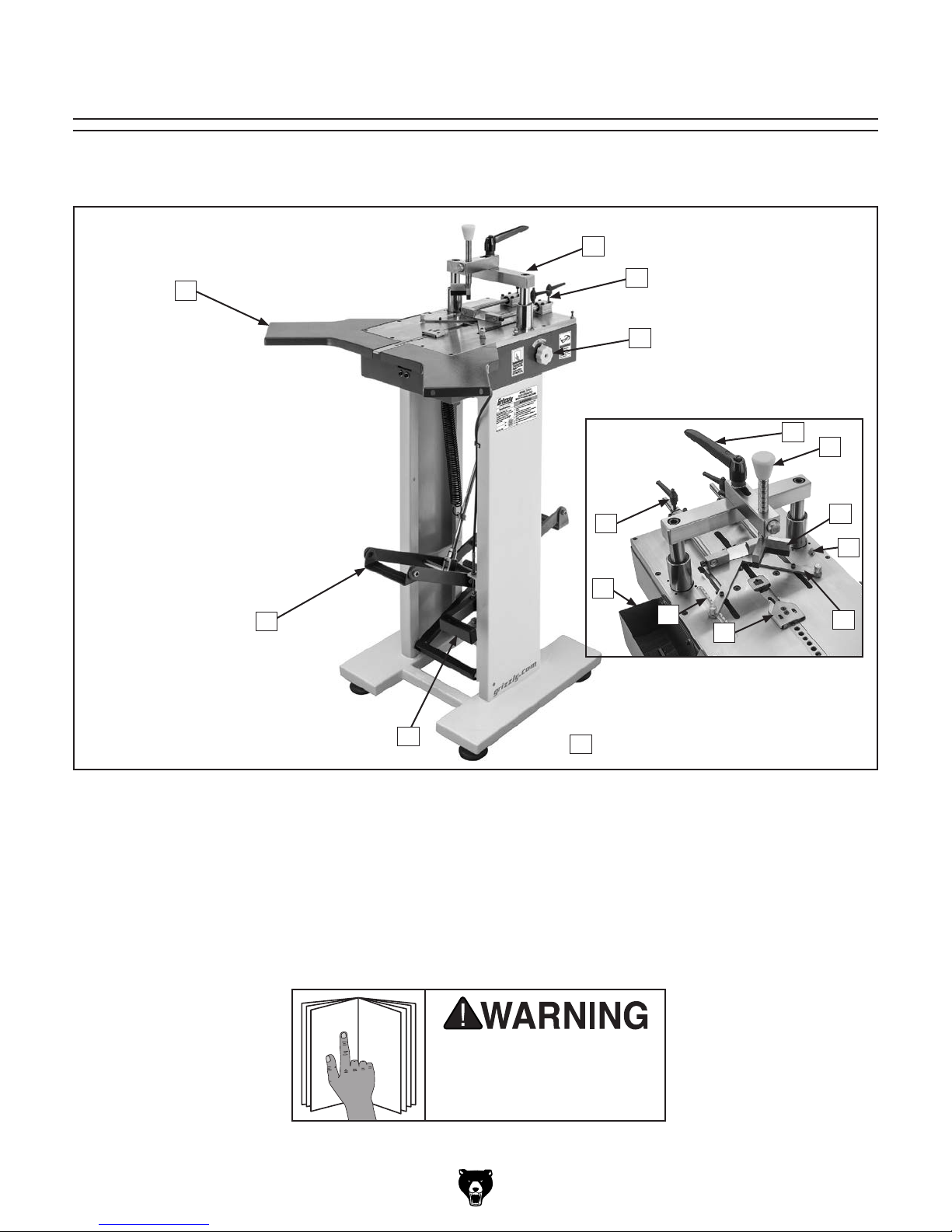
Become familiar with the names and locations of the controls and features shown below to better understand
the instructions in this manual.
B
M
L
C
D
E
F
G
H
K
J
I
A
P
A. Extension Table
B. Pressure Bar Support
C. Rear Position Stop
D. V-Nail Height Dial
E. Pressure Bar Lock
F. Pressure Bar
G. Pressure Pad
H. V-Nail Depth Indicator Light
O
using machine.
N
I. Fence
J. Front Clamp
K. Frame Size Scale
L. Tool Tray
M. Fence Lock Handle
N. Foot Pad
O. Front Clamp Foot Pedal
P. Top Clamp Foot Pedal
-3-
Model T27577 (Mfd. Since 3/16)
Controls & V-Nail
To reduce your risk of
serious injury, read this
entire manual BEFORE
D. Quick-Release Button: Releases pressure
bar for fast height adjustment over workpiece.
Components
using machine.
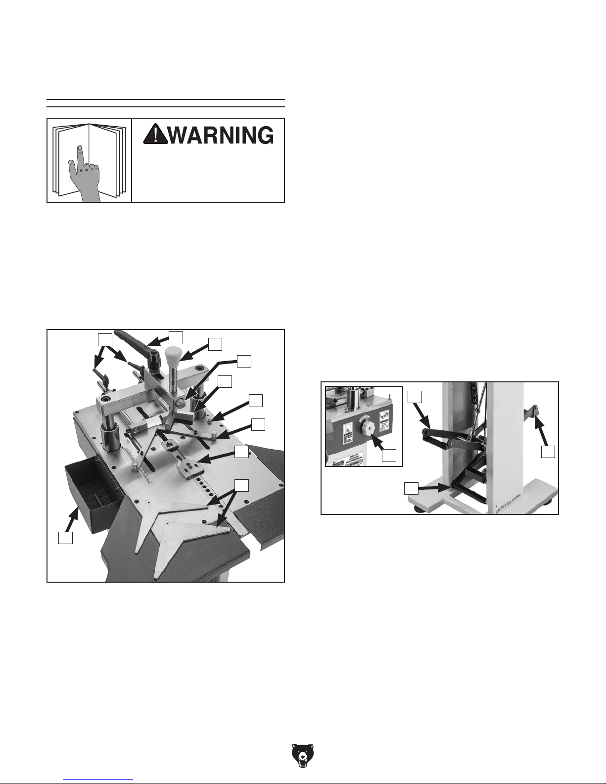
Refer to Figures 1–2 and the following descriptions to become familiar with the basic controls
and components of this machine. Understanding
these items and how they work will help you
understand the rest of the manual and stay safe
when operating this machine.
Table Controls
A
B
C
D
E. Pressure Pad: Holds workpiece firmly from
above as V-nail is inserted from underside of
table. Two pressure pads are included: round
and 90°. Pads thread into bottom of vertical
pressure bar and contact top of workpiece
while V-nail is inserted.
F. V-Nail Depth Indicator Light: Illuminates
when V-nail reaches proper depth.
G. Fence: Adjusts in or out depending upon
workpiece size. Fence angle is 90°.
H. Front Clamp: Secures inside angle during
V-nail insertion. Features two independently
adjustable gripping faces for securing oddshaped miters.
I. 120° & 135° Inserts: Place against fence for
clamping 6- and 8-sided frames.
J. Tool Tray: Holds tools and V-nails.
E
F
G
H
I
J
Figure 1. Table controls.
A. Fence Stop & Lock Handle: Locks fence
setting for consistent V-nail placement.
B. Pressure Bar Lock: Locks pressure bar
position over frame.
L
K
M
Figure 2. Stand controls and V-nail dial.
K. V-Nail Height Dial: Adjusts V-nail driver
depth depending upon size of V-nail used.
Turn dial clockwise for smaller V-nails. Turn
dial counterclockwise for larger V-nails.
L. Pressure Bar Foot Pedals: Controls down-
ward force of pressure bar.
M. Front Clamp Foot Pedal: Controls front
clamp pressure.
L
C. Pressure Bar: Adjusts height of pressure
pad over workpiece. Bar may be handturned, or the quick-release button can be
used for faster vertical bar adjustments.
-4-

Model T27577 (Mfd. Since 3/16)
Machine Data Sheet
MODEL T27577
PICTURE FRAMING MACHINE / UNDERPINNER
Product Dimensions:
Weight ...........................................................................................................................................................................104 lbs.
Width (side-to-side) x Depth (front-to-back) x Height .......................................................................... 28-1/2 x 30 x 48-1/2 in.
Foot Print (Length/Width) ...........................................................................................................................................18 x 15 in.
Shipping Dimensions:
Type ........................................................................................................................................................................ Wood Crate
Weight ............................................................................................................................................................................121 lbs.
Length/Width/Height .....................................................................................................................................43 x 19-1/2 x 23 in.
Must Ship Upright .................................................................................................................................................................Yes
Electrical:
Power Requirement ...................................................................................................................................................9V Battery
Main Specifications:
Capacities
Minimum Frame Width ............................................................................................................................................1/4 in.
Frame/Moulding Width Range ................................................................................................................... 1/4 – 3-5/16
Frame/Moulding Thickness Range .............................................................................................................. 1/4 – 3-1/2
V-Nail Sizes ....................................................................................................................................... 5, 7, 10, 12, 15 mm
Fence Templates .................................................................................................................................. 90, 120, 135 deg.
V-Nail Channel Capacity ................................................................................................................................350 V-Nails
Table Information
Table Length ............................................................................................................................................................18 in.
Table Width ..............................................................................................................................................................12 in.
Table Thickness ......................................................................................................................................................5/8 in.
Ext. Table Width .................................................................................................................................................13-3/4 in.
Ext. Table Length ...............................................................................................................................................13-3/4 in.
Ext. Table Thickness ...............................................................................................................................................1/8 in.
Floor-to-Table Height .........................................................................................................................................37-1/2 in.
Construction
Main Table .................................................................................................................................................................Steel
Ext. Tables ................................................................................................................................................................Steel
Body ..........................................................................................................................................................................Steel
Stand .........................................................................................................................................................................Steel
Paint Type/Finish ......................................................................................................................................Powder Coated
Other Specifications:
Country of Origin ............................................................................................................................................................... China
Warranty ........................................................................................................................................................................... 1 Year
Approximate Assembly & Setup Time ......................................................................................................................20 Minutes
Serial Number Location ................................................................................................................................................ ID Label
ISO 9001 Factory ...................................................................................................................................................................No
CSA Certified .........................................................................................................................................................................No
in.
in.
-5-
Model T27577 (Mfd. Since 3/16)
SECTION 1: SAFETY
For Your Own Safety, Read Instruction
Manual Before Operating This Machine
The purpose of safety symbols is to attract your attention to possible hazardous conditions.
This manual uses a series of symbols and signal words intended to convey the level of importance of the safety messages. The progression of symbols is described below. Remember that
safety messages by themselves do not eliminate danger and are not a substitute for proper
accident prevention measures. Always use common sense and good judgment.
Indicates an imminently hazardous situation which, if not avoided,
WILL result in death or serious injury.
Indicates a potentially hazardous situation which, if not avoided,
COULD result in death or serious injury.
Indicates a potentially hazardous situation which, if not avoided,
MAY result in minor or moderate injury. It may also be used to alert
against unsafe practices.
This symbol is used to alert the user to useful information about
NOTICE
proper operation of the machine.
Safety Instructions for Machinery
OWNER’S MANUAL. Read and understand this
owner’s manual BEFORE using machine.
TRAINED OPERATORS ONLY. Untrained operators have a higher risk of being hurt or killed.
Only allow trained/supervised people to use this
machine.
DANGEROUS ENVIRONMENTS. Do not use
machinery in areas that are wet, cluttered, or have
poor lighting. Operating machinery in these areas
greatly increases the risk of accidents and injury.
DAMAGED PARTS. Regularly inspect machine
for damaged, loose, or mis-adjusted parts—or
any condition that could affect safe operation.
Immediately repair/replace BEFORE operating
machine. For your own safety, DO NOT operate
machine with damaged parts!
AWKWARD POSITIONS. Keep proper footing
and balance at all times when operating machine.
Do not overreach! Avoid awkward hand positions
that make workpiece control difficult or increase
the risk of accidental injury.
FORCING MACHINERY. Do not force machine.
It will do the job safer and better at the rate for
which it was designed.
MAINTAIN WITH CARE. Follow all maintenance
instructions and lubrication schedules to keep
machine in good working condition. A machine
that is improperly maintained could malfunction,
leading to serious personal injury or death.
USE RECOMMENDED ACCESSORIES. Consult
this owner’s manual or the manufacturer for recommended accessories. Using improper accessories will increase the risk of serious injury.
-6-
Model T27577 (Mfd. Since 3/16)
SECTION 2: SETUP
This machine was carefully packaged for safe
transport. When unpacking, separate all enclosed
items from packaging materials and inspect them
for shipping damage.
,
please
IMPORTANT:
you are completely satisfied with the machine and
have resolved any issues between Grizzly or the
shipping agent. You MUST have the original pack-
aging to file a freight claim. It is also extremely
helpful if you need to return your machine later.
Keep children and pets away
from plastic bags or packing
materials shipped with this
Wear safety glasses during
the entire setup process!
Needed for Setup
The following items are needed, but not included,
for the setup/assembly of this machine.
Description Qty
• Additional People ....................................... 1
• Safety Glasses ........................................... 1
• Cleaner/Degreaser ..................... As Needed
• Disposable Shop Rags ............... As Needed
• Straightedge 24" ......................................... 1
• 9V Battery ................................................... 1
Unpacking
If items are damaged
call us immediately at (570) 546-9663.
Save all packaging materials until
SUFFOCATION HAZARD!
machine. Discard immediately.
-7-
Model T27577 (Mfd. Since 3/16)
Inventory
The following is a list of items shipped with your
machine. Before beginning setup, lay these items
out and inventory them.
If any non-proprietary parts are missing (e.g. a
nut or a washer), we will gladly replace them; or
for the sake of expediency, replacements can be
obtained at your local hardware store.
NOTICE
If you cannot find an item on this list, carefully check around/inside the machine and
packaging materials. Often, these items get
lost in packaging materials while unpacking or they are pre-installed at the factory.
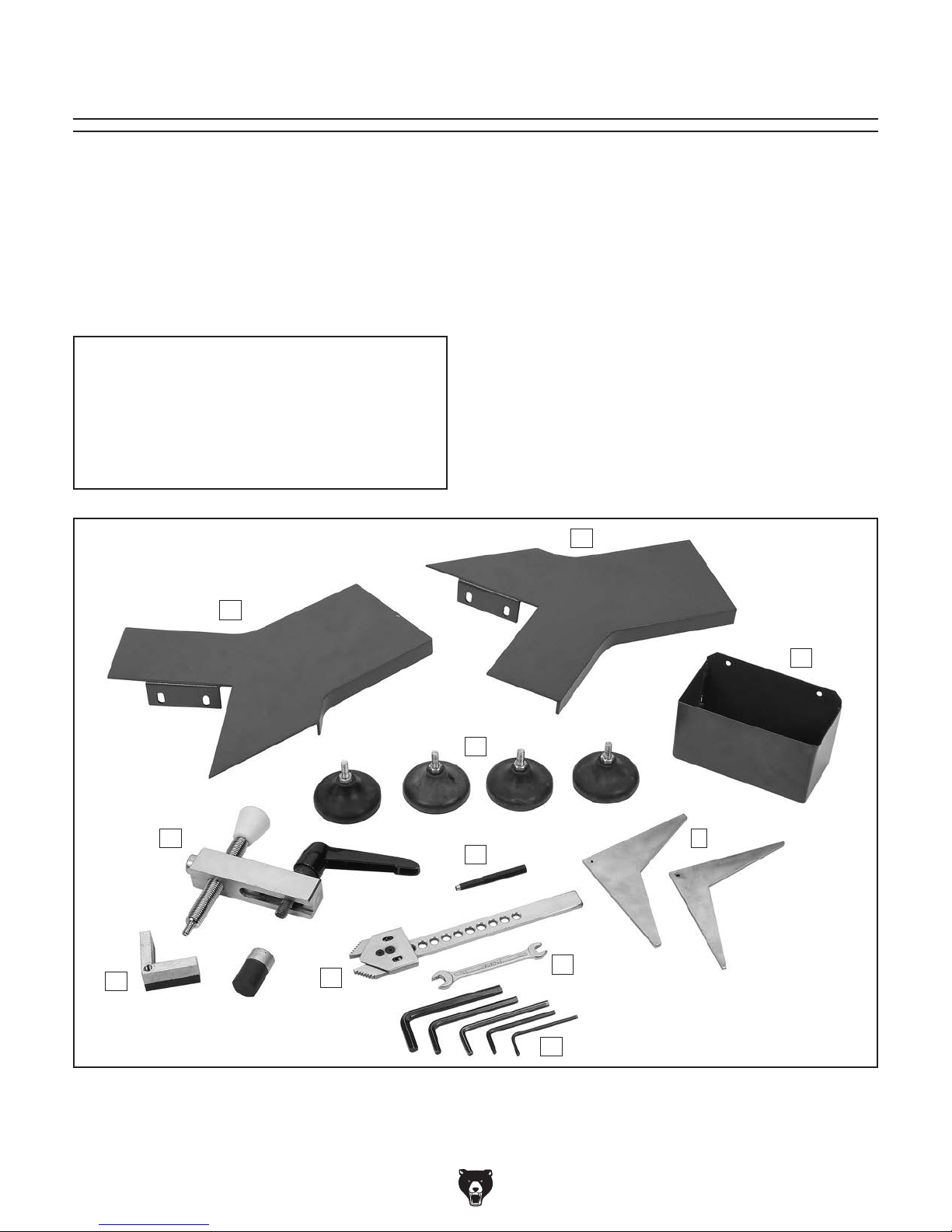
Inventory (Figure 3): Qty
A. Extension Tables ........................................ 2
B. Too l Tray ..................................................... 1
C. Rubber Feet ............................................... 4
D. Vertical Clamp Assembly ........................... 1
E. Magnetic Tool ............................................. 1
F. Angle Inserts: 120° & 135° ...................1 Ea.
G. Pressure Pad: Round & 90° .................1 Ea.
H. Front Clamp ................................................ 1
I. Open-End Wrench 8/10mm ........................ 1
J. Hex Wrench Set: 2.5, 3, 4, 5, 6mm ......1 Ea.
K. Hardware (not shown)
—Cap Screws M6-1 x 10 ......................... 10
—Flat Washers 6mm ............................... 10
A
G
A
B
C
D
E
I
H
J
F
-8-
Figure 3. Model T27577 inventory.
 Loading...