

Page 1

MODELS T27555-56, T27575
PORTABLE
BLADE WELDER
INSTRUCTIONS
For questions or help with this product contact Tech Support at (570) 546-9663 or techsupport@grizzly.com
Introduction
This portable blade welder can cut, weld, anneal,
and grind bandsaw blades, which is commonly
done in the following situations:
• To rejoin a blade that has been purposely cut
for making an internal contour cut.
• To repair a broken blade that is still sharp and
useful.
• To fabricate a new blade from bulk blade
material.
Hot sparks from the welding process can
damage your eyes and skin. During welding
operations, always wear safety goggles and
protective gear to reduce your risk.
Specifications
T27555 2.0 KVA Blade Welder
Range of Blade Widths (Carbon Steel) ....
Range of Blade Widths (Bi-Metal) ............
Blade Thickness ........................................ 0.025"
Power Supply Requirement ..................110V, 15 A
Prewired Voltage ......................................... 110 V
Welding Power.........................................2.0 kVA
Shipping Weight ....................................... 44 lbs.
T27575 2.4 KVA Blade Welder
Range of Blade Widths (Carbon Steel) ....
Range of Blade Widths (Bi-Metal) ............
Blade Thickness ........................................ 0.025"
Power Supply Requirement ..................110V, 15 A
Prewired Voltage ......................................... 110 V
Welding Power.........................................2.4 kVA
Shipping Weight ........................................46 lbs.
1
⁄8" –1⁄2 "
1
⁄8" –3⁄8"
1
⁄8" –5⁄8"
1
⁄8" –1⁄2 "
Figure 1. Model T27556 blade welder.
COPYRIGHT © FEBRUARY, 2016 BY GRIZZLY INDUSTRIAL, INC. REVISED JULY, 2017 (BL)
NO PORTION OF THIS MANUAL MAY BE REPRODUCED IN ANY SHAPE
OR FORM WITHOUT THE WRITTEN APPROVAL OF GRIZZLY INDUSTRIAL, INC.
(FOR MODELS MFD. SINCE 12/15) #BL17991 PRINTED IN TAIWAN
T27556 4.2 KVA Blade Welder
1
Range of Blade Widths (Carbon Steel) ....
Range of Blade Widths (Bi-Metal) ............
⁄8" –3⁄4"
1
⁄8" –5⁄8"
Blade Thickness ........................................ 0.025"
Power Supply Requirement ................. 2 20V, 15A
Welding Power.........................................4.2 kVA
Shipping Weight ........................................50 lbs.
Page 2

Identification
To reduce your risk of
serious injury, read this
entire manual BEFORE
Welding
Clamps
Blade
Shear
Grinder
ON/OFF
Switch
Welder
Button
Carrying Handle
Annealing
Button
Clamping
Pressure
Dial
Spark Deflector
Clamp Levers
Anneal
Strength
Switch
(T27556
Only)
-2-
Figure 2. Identification (Model T27556 shown).
Grinding
Wheel
using machine.
T27555-75 Blade Welder (Mfd. 12/15+)
Page 3

Safety for Blade Welders
WELDING FUMES. Breathing welding fumes can
cause respiratory damage. Maintain adequate ventilation during and after welding operations.
PREVENT FIRES. Welding work zones must be
kept clear of flammable liquids or gases, such as
gasoline or solvents, and combustible solids, such
as paper or wood, especially any built-up dust
from this same material. Provide approved fire
extinguishing equipment for the welding zone. Stay
alert for sparks and spatter thrown into cracks and
crevices that can start a smoldering fire.
PERSONAL PROTECTIVE EQUIPMENT. Wear
eye and body protection approved for welding operations, such as safety goggles, a face shield, clean
and oil-free protective clothing, leather gloves, long
sleeves, and cuffless pants. Protect other people
and property in the welding work zone from exposure to sparks and hot spatter.
STABLE WORK SURFACE. Always make sure
the welder is mounted on a stable and lever surface before operations. If the welder unexpectedly moves during operation, burns, lacerations, or
abrasion injuries could occur.
ABRASION INJURIES. The grinding wheel can
remove skin very quickly. Always keep your fingers
and hands away from the spinning grinding wheel
to reduce this risk.
ELECTRIC & MAGNETIC FIELDS (EMF). Welding
operations create EMF around the welding equipment and workpieces. Workers who have pacemakers must consult with their physician before
using this equipment or stay at least 50 feet from
welding operations.
EQUIPMENT MAINTENANCE. Make sure equipment inspections and maintenance are performed
by a qualified person. Stop the welding operation
and disconnect the welder from power if the equipment is damaged or malfunctions.
BLADE BREAKAGE. Blades that are not welded
correctly can break under the stresses of using
them on the bandsaw. Have only one weld on a
blade. Always inspect the weld as instructed. Make
sure the annealing and grinding process does not
compromise the integrity of the weld. If you have
any doubt about weld quality, start over.
If you have never used this type of welder before, WE STRONGLY RECOMMEND that you read
books, trade magazines, or get formal training before beginning any projects. Regardless of the
content in this section, Grizzly Industrial will not be held liable for accidents caused by lack of
training.
T27555-75 Blade Welder (Mfd. 12/15+)
-3-
Page 4

Note: Circuit requirements in this manual apply to
a dedicated circuit—where only one machine will
be running on the circuit at a time. If machine will
be connected to a shared circuit where multiple
machines may be running at the same time, consult an electrician or qualified service personnel to
ensure circuit is properly sized for safe operation.
A power supply circuit includes all electrical
equipment between the breaker box or fuse panel
in the building and the machine. The power supply circuit used for this machine must be sized to
safely handle the full-load current drawn from the
machine for an extended period of time. (If this
machine is connected to a circuit protected by
fuses, use a time delay fuse marked D.)
Circuit Information
or equipment damage
not properly grounded
This machine MUST be grounded. In the event
of certain malfunctions or breakdowns, grounding
reduces the risk of electric shock by providing a
path of least resistance for electric current.
Improper connection of the equipment-grounding
wire can result in a risk of electric shock. The
wire with green insulation (with or without yellow
stripes) is the equipment-grounding wire. If repair
or replacement of the power cord or plug is necessary, do not connect the equipment-grounding
wire to a live (current carrying) terminal.
Check with a qualified electrician or service personnel if you do not understand these grounding
requirements, or if you are in doubt about whether
the tool is properly grounded. If you ever notice
that a cord or plug is damaged or worn, disconnect it from power, and immediately replace it with
a new one.
For your own safety and protection of
We do not recommend using an extension cord
with this machine.
cord, only use it if absolutely necessary and only
on a temporary basis.
Extension cords cause voltage drop, which can
damage electrical components and shorten motor
life. Voltage drop increases as the extension cord
size gets longer and the gauge size gets smaller
(higher gauge numbers indicate smaller sizes).
Any extension cord used with this machine must
be in good condition and contain a ground wire
and matching plug/receptacle. Additionally, it must
meet the following size requirements:
Extension Cords
Power Supply
Electrocution, fire, shock,
may occur if machine is
and connected to power
supply.
property, consult an electrician if you are
unsure about wiring practices or electrical
codes in your area.
Grounding Requirements
If you must use an extension
Minimum Gauge Size ...........................12 AWG
Maximum Length (Shorter is Better).......50 ft.
-4-
T27555-75 Blade Welder (Mfd. 12/15+)
Page 5

it will not fit the outlet, have a qualified
electrician install the proper outlet with a
T27555 & T27575 Circuit
This machine is equipped with a power cord that
has an equipment-grounding wire and a grounding
plug. Only insert plug into a matching receptacle
(outlet) that is properly installed and grounded in
accordance with all local codes and ordinances.
DO NOT modify the provided plug!
This machine is prewired to operate on a power
supply circuit that has a verified ground and meets
the following requirements:
No adapter should be used with plug. If
Requirements
Nominal Voltage .................... 110V, 115 V, 120V
Cycle ..........................................................60 Hz
Phase ........................................... Single-Phase
Power Supply Circuit ......................... 15 Amps
Plug/Receptacle ............................. NEMA 5-15
GROUNDED
5-15 RECEPTACLE
T27556 Circuit Requirements
Nominal Voltage .........208V, 220V, 2 3 0V, 240V
Cycle ..........................................................60 Hz
Phase ........................................... Single-Phase
Power Supply Circuit ......................... 15 Amps
Plug/Receptacle ............................. NEMA 6-15
GROUNDED
6-15 RECEPTACLE
Current Carrying Prongs
Grounding Prong
5-15 PLUG
Neutral Hot
Figure 3. Typical 5-15 plug and receptacle.
SHOCK HAZARD!
Two-prong outlets do not meet the grounding
requirements for this machine. Do not modify
or use an adapter on the plug provided—if
verified ground.
6-15 PLUG
Grounding Prong
Figure 4. Typical 6-15 plug and receptacle.
plug does not fit available receptacle, or if
machine must be reconnected for use on a
different type of circuit, reconnection must
be performed by an electrician or qualified
service personnel, and it must comply with
all local codes and ordinances.
T27555-75 Blade Welder (Mfd. 12/15+)
-5-
Page 6

Operations
Overview
This blade welder uses electrical resistance (induction) to weld bandsaw blade ends. Afterwards, the
annealing process gives the weld strength and
flexibility.
Hot sparks from the welding process can
damage your eyes and skin. During welding
operations, always wear safety goggles and
protective gear to reduce your risk.
Blade Shear
To use the blade shear, place the back of the
blade evenly against the back of the blade shear,
as shown in Figure 5, then firmly pull the handle
down to square off the blade end.
Blade Preparation
When welding the blade, the ends must evenly
butt up against each other and be square. This
will ensure the that the weld is of even thickness
for the full width of the blade.
To prepare the blade for welding:
1. Be sure to grind off any teeth that are in the
blade welding zone (see Figures 6–7).
Note: Make sure the blade ends are even
with each other after grinding them.
Welding Zone
Grind Off
Figure 6. Blade ends and welding zone.
Handle
Figure 5. Using the blade shear to cut the blade.
-6-
Figure 7. Using the grinder.
T27555-75 Blade Welder (Mfd. 12/15+)
Page 7

Note: You can make sure that the blade ends
are even with each other by stacking them
together with the teeth facing in opposite
directions (see Figure 8), then grinding them.
Regardless of the grinding angle, the blade
ends will match evenly for welding.
Figure 8. Blade ends stacked with teeth facing
opposite directions.
2. Use 120-grit emery cloth or an equivalent to
lightly sand the part of the blade that will contact the welding clamps. This helps ensure
a good electrical contact with the blade for
welding.
Note: To prevent dulling the teeth, keep the
emery cloth away from them when sanding
the blade surface.
Welding
1. DISCONNECT WELDER FROM POWER!
2. Thoroughly clean the welding clamps to
remove debris, oily substances, or flash from
previous welding operations. If necessary,
lightly sand clamps with 120-grit emery cloth.
3. Fully rotate the clamping pressure dial
(see Figure 9) clockwise. This spreads the
welding clamps apart to allow proper positioning of the blade ends.
Clamping
Welding
Clamp
Figure 9. Clamping controls.
4. Loosen the welding clamps by pulling the
clamp levers down.
5. Position the back of one blade end evenly
against the back of the right welding clamp so
the end is midway between the two clamps,
then rotate the clamp lever as far up as possible to hold the blade end in place (see
Figure 10).
Pressure
Dial
Clamp
Lever
T27555-75 Blade Welder (Mfd. 12/15+)
Blade
End
Figure 10. Blade end properly positioned in
welding clamp and locked in place.
-7-
Page 8
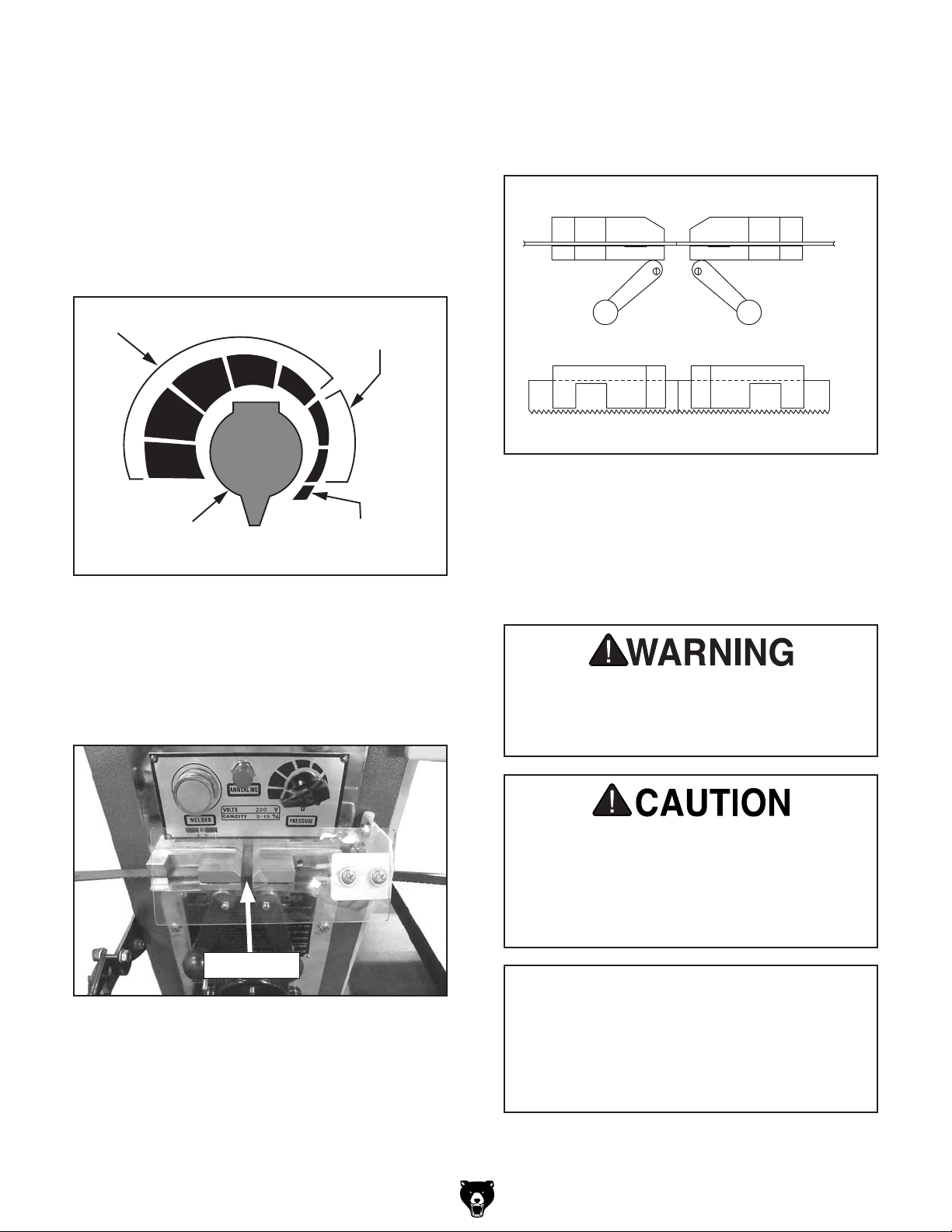
6. Use the illustration in Figure 11 to set the
correct clamping pressure setting for the
width of the blade.
Note: The clamping pressure presses the
blade ends together to help form a strong
weld. The pressure scale is an approximation
only. If you have difficulty getting satisfactory
welds, experiment by increasing or decreasing this pressure.
Note: To ensure a good blade weld, it is
critical that the blade ends are secured in the
welding clamps evenly and with no overlap
(see Figure 13).
Blade Ends Flat w/No Overlap
Front View
Above
3
⁄8" Blade
Clamping
Pressure
Dial
1
⁄4"-3⁄8" Blade
Up to
1
⁄4" Blade
Figure 11. Blade clamping pressure settings.
7. Place the other blade end in the left welding
clamp. Position it so that it evenly butts up
against the opposing blade end, then clamp
it in place by rotating the left clamp lever up
(see Figure 12).
Blade Ends Butt Evenly
Top View
Figure 13. Blade ends correctly secured in
welding clamps.
8. Put on safety goggles and heavy leather
gloves.
9. Connect the welder to power.
Light generated during the welding process
could cause serious eye injury. To reduce
your risk, always wear eye protection
approved for welding during this process.
Blade Ends
Figure 12. Blade ends in correct position for
welding.
-8-
Burning sparks may be thrown in all directions while welding. Protect yourself from
injury by not welding near flammables and
wearing spark-resistant clothing/gloves.
Keep fire extinguishing equipment readily
available.
NOTICE
For good metal-to-metal contact between
welding clamps and blade, make sure
blades and clamps are free from any debris,
coatings, or flash before and after each use
of the welding station.
T27555-75 Blade Welder (Mfd. 12/15+)
Page 9

Before welding a blade back together to
perform an internal cut, insulate entire blade
from all metal surfaces of the bandsaw to
ensure a good flow of current through the
blade.
10. Press welder button until the blade joint
returns to the original color. IMPORTANT:
Releasing the welder button immediately
may cause weld failure.
Note: A limit switch senses the electrical
resistance between the blade ends. If there is
an adequate amount of welded material, the
limit switch will not allow the welder button to
activate the operation again.
14. Inspect the weld. The welded joint should be
even across the width of the blade with no
gaps (see Figure 14).
Correct
Not Correct
Not Correct
Figure 14. Blade welding joint examples.
11. Allow the blade to cool.
12. Rotate the clamping pressure dial fully clock-
wise to release the clamp pressure.
13. Remove the blade.
— If the weld is satisfactory, anneal the weld
as instructed in the next subsection.
— If the weld is NOT satisfactory, use the
blade shear to completely remove the weld
and repeat the Blade Preparation and
Welding procedures beginning on Page 6.
T27555-75 Blade Welder (Mfd. 12/15+)
-9-
Page 10

Correct
Not Correct
Not Correct
Annealing Weld
Once the blade ends are welded, the metal
becomes hard and brittle, which is not suitable
for a bandsaw blade that must continuously bend
smoothly under stress.
5. Allow the blade to completely cool.
6. Remove the blade from the welding clamps.
7. Grind the weld flat on both sides so the blade
will run smoothly on the bandsaw wheels.
To bring the weld strength and flexibility to acceptable levels for a bandsaw blade, it must be
annealed. The annealing process re-heats the
weld area, then allows it to cool gradually, improving its strength enough to meet the flexibility
requirements for the blade.
To anneal the weld:
1. Place the blade in the welding clamps so that
the weld is centered between the clamps.
2. Secure the blade by moving clamp levers up.
3. T27556 Only: Set the "Anneal Strength"
switch (see Figure 15) to the proper position for the width of the blade. Use WEAK for
1
⁄8"–3⁄8" (3–10mm) wide blades and STRONG
7
⁄16"–3⁄4" (11–19mm) wide blades.
for
Annealing
Button
Note: Make sure not to grind the teeth or
blade body. Be careful to avoid overheating
the blade while grinding—this will weaken the
blade.
8. For Bi-Metal Blades Only: Repeat Steps
4–5 (not Step 6).
9. Test the strength and flexibility of the weld by
bending the blade in an arc (with the weld at
the top of the arc) similar in size and shape of
the bandsaw wheels. The blade should bend
smoothly without any angles (see Figure 16).
Correct
Anneal
Strength
Switch
(T27556)
Figure 15. Annealing controls.
4. For Carbon Steel Blades: Rapidly press
and release the annealing button repeatedly
(see Figure 15) until the weld zone turns a
dull red color. (DO NOT press and hold the
annealing button.) Continue pressing the
annealing button with decreasing frequency
until the weld no longer glows.
For Bi-Metal Blades: Rapidly press and
release the annealing button repeatedly until
the weld zone starts to glow, then immediately stop pressing the annealing button
completely.
Not Correct
Figure 16. Comparison of correct and incorrect
blade weld bends.
— If the blade does show signs of bending or
breaking at the weld, use the blade shear
to completely remove the weld and perform
the Blade Preparation and Welding procedures again that begin on Page 6.
10. DISCONNECT WELDER FROM POWER!
11. Thoroughly clean the welding clamps to
remove debris, oily substances, or flash from
previous welding operations. If necessary,
lightly sand them with 120-grit emery cloth.
-10 -
T27555-75 Blade Welder (Mfd. 12/15+)
Page 11

Troubleshooting
Review the troubleshooting and procedures in this section if a problem develops with your machine. If
you need replacement parts or additional help with a procedure, call our Technical Support.
gather the serial number and manufacture date of your machine before calling.
Symptom Possible Cause Possible Solution
Machine does not
start or a breaker
trips.
Weld is misaligned. 1. Debris or flash on weld clamps or blade.
Weld not complete
(has blow-holes)
Weld breaks or is
brittle.
1. Plug/receptacle is at fault or wired
incorrectly.
2. Wall fuse/circuit breaker is blown/tripped.
3. Wiring is open/has high resistance.
4. Welder button is at fault.
2. Blade ends not cut off square.
3. Blade ends not evenly butted in clamps.
4. Clamping pressure not set correctly.
1. Blade ends not clamped properly.
2. Blade ends not even with each other.
1. Weld not correctly annealed.
2. Weld is ground too thin.
3. Debris or oil in weld.
4. Blade overheated during grinding.
1. Test for good contacts; correct the wiring.
2. Ensure circuit size is suitable for this machine;
replace weak breaker.
3. Check for broken wires or disconnected/corroded
connections, and repair/replace as necessary.
4. Replace welder button.
1. Remove debris, oily substances, or flash from weld
clamps and blade.
2. Use the blade shear to cut blades; grind ends
together (see Note on top of Page 7).
3. Make sure blade ends are evenly butted against each
other before securing with clamp levers (Page 8).
4. Set clamping pressure correctly (Page 8).
1. Make sure blade ends are evenly butted against
each other in clamps; use the correct clamping
pressure (Page 8).
2. Use the blade shear to cut blades; grind ends
together (see Note at top of Page 7).
1. Correctly perform the annealing procedure on
Page 9.
2. Only grind flash even with blade body.
3. Make sure clamps and blade ends are clean of
debris, oily substances, and flash.
4. Use light passes with the grinding wheel.
Note: Please
T27555-75 Blade Welder (Mfd. 12/15+)
-11-
Page 12

T27555 Wiring Diagram
ON
OFF
T27555
WELDING UNIT
(Viewed from Behind)
Clamp
Pressure
Dial
Right
Welding
Clamp
Annealing
Button
OMRON
V-15-1E5
15A 125VAC
1
23
Left
Welding
Clamp
Transformer
Ya Chang Electric Co.
115/230V 2.0 KVA
3NO
2NC
Sensor
OMRON
V-15-1E5
1
Welding Button
4 3
NO
AUSPICIOUS
APB25-1/0
10A 250VAC
2 1
Start
Capacitor
YuhChang
3MFD
250VAC
1 2 3 4 5
1 2 3 4 5 6 7
Grinder
Switch
1
Grinder
Motor
3
2
4
6
5
SCI
R13-5
10A 125V
Ground
2
4
6
110 VAC
5-15 Plug
Neutral
5
Hot
Ground
-12-
The photos and diagrams
included in this section are
best viewed in color. You
can view these pages in
color at www.grizzly.com.
T27555-75 Blade Welder (Mfd. 12/15+)
Page 13
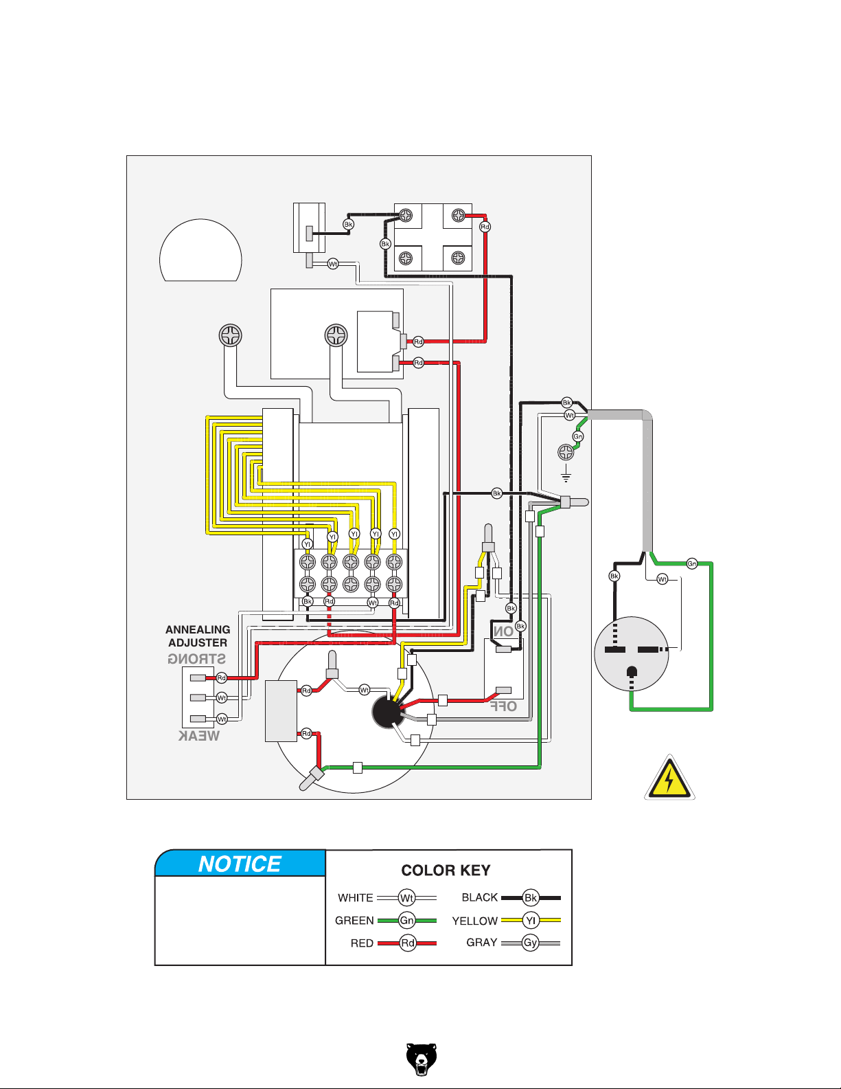
T27556 Wiring Diagram
ON
OFF
STRONG
WEAK
ANNEALING
ADJUSTER
T27556
WELDING UNIT
(Viewed from Behind)
Clamp
Pressure
Dial
Right
Welding
Clamp
Annealing
Button
1
2
Left
Welding
Clamp
Transformer
115/230V 4.2 KVA
220V
Welding Button
Sensor
OMRON
Z-15GSB
4 3
NO
10A 250VAC
2 1
Ground
4
6
1 2 3 4 5
1
2
3
Capacitor
Start
3MFD
250VAC
The photos and diagrams
included in this section are
best viewed in color. You
can view these pages in
color at www.grizzly.com.
Grinder
Motor
6
2
5
3
3
Grinder
2
Switch
1
4
5
Hot
Hot
Ground
220 VAC
6-15 Plug
T27555-75 Blade Welder (Mfd. 12/15+)
-13-
Page 14

T27575 Wiring Diagram
ON
OFF
T27575
WELDING UNIT
(Viewed from Behind)
Clamp
Pressure
Dial
Right
Welding
Clamp
Annealing
Button
OMRON
V-15-1E5
15A 125VAC
1
23
Left
Welding
Clamp
Transformer
Ya Chang Electric Co.
115/230V 2.4 KVA
Welding Button
3NO
2NC
Sensor
OMRON
V-15-1E5
1
4 3
NO
AUSPICIOUS
APB25-1/0
10A 250VAC
2 1
1 2 3 4 5
Start
Capacitor
YuhChang
3MFD
250VAC
Grinder
Motor
5
The photos and diagrams
included in this section are
best viewed in color. You
can view these pages in
color at www.grizzly.com.
Grinder
Switch
2
4
6
1
3
SCI
R13-5
10A 125V
Ground
2
4
6
110 VAC
5-15 Plug
Neutral
5
Hot
Ground
-14-
T27555-75 Blade Welder (Mfd. 12/15+)
Page 15

Blade Shear & Cabinet
18
17
21
26
26
28
19
27
32
31
36
29
2
1
5
10
9
3
4
3
12
13
11
3
11
3
22
33
38
35
30
37
34
6
7
8
8
4
14
15
16
REF PART # DESCRIPTION REF PART # DESCRIPTION
1 PT27555001 FLAT WASHER 8MM 20 PT27555020 CABINET FEET W/MOUNTING HOLES
2 PT27555002 BALL KNOB 5/16-18 (BLACK) 21 PT27555021 CABINET (T27555, T27575)
3 PT27555003 FLAT WASHER 6MM 21 PT27556021 CABINET (T27556)
4 PT27555004 CAP SCREW M6-1 X 25 22 PT27555022 HEX NUT M6-1
5 PT27555005 CAP SCREW M8-1.25 X 20 25 PT27555025 HEX BOLT M6-1 X 25
6 PT27555006 LOWER SHEAR BLADE 26 PT27555026 PHLP HD SCR M5-.8 X 8
7 PT27555007 ALIGNMENT BRACKET 27 PT27555027 SPARK DEFLECTOR HINGE
8 PT27555008 CAP SCREW M5-.8 X 8 28 PT27555028 PHLP HD SCR M5-.8 X 8
9 PT27555009 UPPER SHEAR BLADE 29 PT27555029 HEX NUT M5-.8
10 PT27555010 SHEARING LEVER 5/16-18 30 PT27555030 SPARK DEFLECTOR
11 PT27555011 HEX NUT M6-1 31 PT27555031 PHLP HD SCR M5-.8 X 12
12 PT27555012 LOCKING LINK 8.25 X 21MM 32 PT27555032 FLAT WASHER 5MM
13 PT27555013 LOCKING LINK PIN 3.5 X 10.5MM 33 PT27555033 PHLP HD SCR M5-.8 X 12
14 PT27555014 LOCKING LINK PIN 3.5 X 10.5MM 34 PT27555034 HEX NUT M5-.8
15 PT27555015 LOCKING LINK 8.5 X 21MM 35 PT27555035 SPARK DEFLECTOR BRACKET (LEFT)
16 PT27555016 LOCKING LINK CLIP 36 PT27555036 SPARK DEFLECTOR BRACKET (RIGHT)
17 PT27555017 HANDLE 37 PT27555037 PHLP HD SCR M5-.8 X 12
18 PT27555018 PHLP HD SCR M8-1.25 X 16 38 PT27555038 HEX NUT M5-.8
19 PT27555019 HEX NUT M8-1.25 39 PT27555039 PHLP HD SCR M5-.8 X 8
25
20
20
25
T27555-75 Blade Welder (Mfd. 12/15+)
-15-
Page 16
155
153
162
123
154
160
T27555/T27575 Controls & Electrical
152
151
164
101
160
131
120
119
161
170
103
122
131
145
165
171
173
174
127
145
126
165
172
136
145
118
102
116
115
125
180
186
156
115
198
187
188
169
169
128
104
116
185
174
132
186
184
166
117
106
161
167
166
174
166
113
110
178
111
166
179
112
167
107
121
163
145
124
160
145
106
178
114
109
169
105
135
179
161
114
108
109
183
129
130
-16 -
T27555-75 Blade Welder (Mfd. 12/15+)
Page 17

T27555/T27575 Controls & Electrical Parts
We do our best to stock replacement parts when possible, but we cannot guarantee that all parts shown
are available for purchase. Call (800) 523-4777 or visit www.grizzly.com/parts to check for availability.
REF PART # DESCRIPTION REF PART # DESCRIPTION
101 PT27555101 SENSOR OMRON V-151E5 110V/220V 135 PT27555135 CONNECTING PLATE (RIGHT)
102 PT27555102 GUIDE BLOCK 136 PT27555136 INSULATING SLEEVE
103 PT27555103 GUIDE CASTING 145 PT27555145 FLAT WASHER 5MM
104 PT27555104 FRONT PANEL 151 PT27555151 FLAT WASHER 6MM
105 PT27555105 ELECTRODE (RIGHT) 152 PT27555152 LOCK WASHER 6MM
106 PT27555106 CAM PIVOT SHAFT 153 PT27555153 FLANGE NUT M6-1
107 PT27555107 CLAMP LEVER (LEFT) 154 PT27555154 SPACER
108 PT27555108 CLAMP LEVER (RIGHT) 155 PT27555155 HEX BOLT M6-1 X 16
109 PT27555109 BALL KNOB M8-1.25 (BLACK) 156 PT27555156 LOCK WASHER #8
110 PT27555110 LOWER JAW (LEFT) 160 PT27555160 HEX NUT M5-.8
111 PT27555111 LOWER JAW (RIGHT) 161 PT27555161 LOCK WASHER 5MM
112 PT27555112 JAW INSULATOR 162 PT27555162 CAP SCREW M5-.8 X 25
113 PT27555113 ELECTRODE (LEFT) 163 PT27555163 PHLP HD SCR 5-40 X 3/4
114 PT27555114 EXT RETAINING RING 5MM 164 PT27555164 LOCK WASHER #5
115 PT27555115 ON BUTTON AUSPICIOUS APB 25-1/0 165 PT27555165 CAP SCREW M5-.8 X 8
116 PT27555116 ANNEAL BUTTON OMRON V15-1E5 166 PT27555166 RIVET 2 X 6MM NAMEPLATE, STEEL
117 PT27555117 CLAMPING PRESSURE KNOB M6-1 167 PT27555167 CAP SCREW M5-.8 X 6
118 PT27555118 ANNEAL SWITCH BRACKET 169 PT27555169 FLAT HD SCR M5-.8 X 12
119 PT27555119 SPRING ARM BRACKET 170 PT27555170 CAP SCREW M5-.8 X 16
120 PT27555120 CAM 171 PT27555171 INT TOOTH WASHER 5MM
121 PT27555121 SPRING ARM 172 PT27555172 FLAT WASHER 5MM
122 PT27555122 UPPER EXTENSION SPRING 1 X 9 X 20 173 PT27555173 INSULATING WASHER 5MM
123 PT27555123 LOWER EXTENSION SPRING 1 X 10 X 40 174 PT27555174 PHLP HD SCR M5-.8 X 10
124 PT27555124 WELDING TRANSFORMER 110V 2.0 KVA (T27555) 178 PT27555178 LOCKING FLANGE SCREW M8-1.25 X 16
124 PT27575124 WELDING TRANSFORMER 110V 2.4 KVA (T27575) 179 PT27555179 LOCK WASHER 8MM
125 PT27555125 TOGGLE SWITCH SEI R13-5 180 PT27555180 STRAIN RELIEF TYPE-3 M16-1.5
126 PT27555126 MOTOR 1/8HP 110V 1-PH 183 PT27555183 PWR CORD 16G 3W 90" 5-15
127 PT27555127 S CAPACITOR 3M 250V 1/2 X 7/8 X 1-1/4 184 PT27555184 HEX NUT 1/4-20
128 PT27555128 GRINDING WHEEL 1/4 X 5/8 X 2-1/2 185 PT27555185 FLAT WASHER 1/4
129 PT27555129 GRINDING WHEEL GUARD 186 PT27555186 FLAT WASHER 1/4
130 PT27555130 GUARD RETAINING RING 187 PT27555187 HEX NUT 8-32 THIN
131 PT27555131 CAP SCREW M5-.8 X 25 188 PT27555188 HEX NUT M12-1.0 THIN
132 PT27555132 CONNECTING PLATE (LEFT) 198 PT27555198 FLAT HD SCR M5-.8 X 15
T27555-75 Blade Welder (Mfd. 12/15+)
-17-
Page 18

162
155
153
123
154
160
145
124
121
164
163
160
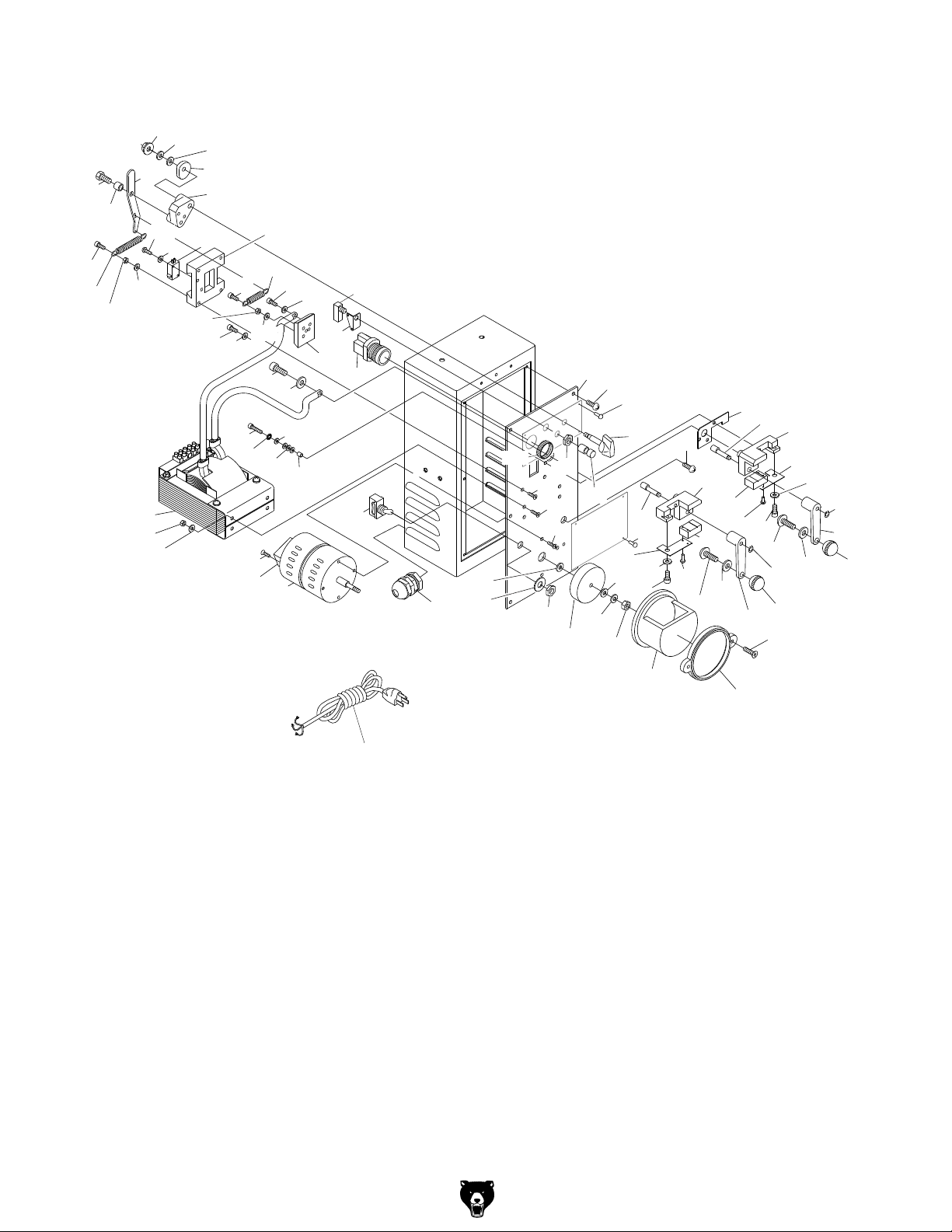
T27556 Controls & Electrical
152
151
120
119
131
161
170
171
174
127
103
122
145
165
173
145
126
165
172
136
145
102
118
195
116
115
125
180
115
156
198
169
A
187
188
128
104
116
186
174
133
186
185
166
117
167
184
101
160
131
145
106
166
132
161
178
156
113
110
166
179
187
107
112
111
166
106
167
178
114
169
105
179
109
135
161
114
108
109
183
129
130
-18-
T27555-75 Blade Welder (Mfd. 12/15+)
Page 19

T27556 Controls & Electrical Parts
REF PART # DESCRIPTION REF PART # DESCRIPTION
101 PT27556101 SENSOR OMRON Z-15GSB 136 PT27556136 INSULATING SLEEVE
102 PT27556102 GUIDE BLOCK 145 PT27556145 FLAT WASHER 5MM
103 PT27556103 GUIDE CASTING 151 PT27556151 FLAT WASHER 6MM
104 PT27556104 FRONT PANEL 152 PT27556152 LOCK WASHER 6MM
105 PT27556105 ELECTRODE (RIGHT) 153 PT27556153 FLANGE NUT M6-1
106 PT27556106 CAM PIVOT SHAFT 154 PT27556154 SPACER
107 PT27556107 CLAMP LEVER (LEFT) 155 PT27556155 HEX BOLT M6-1 X 16
108 PT27556108 CLAMP LEVER (RIGHT) 156 PT27556156 LOCK WASHER #8
109 PT27556109 BALL KNOB M8-1.25 (BLACK) 160 PT27556160 HEX NUT M5-.8
110 PT27556110 LOWER JAW (LEFT) 161 PT27556161 LOCK WASHER 5MM
111 PT27556111 LOWER JAW (RIGHT) 162 PT27556162 CAP SCREW M5-.8 X 25
112 PT27556112 JAW INSULATOR 163 PT27556163 PHLP HD SCR 5-40 X 3/4
113 PT27556113 ELECTRODE (LEFT) 164 PT27556164 LOCK WASHER #5
114 PT27556114 EXT RETAINING RING 5MM 165 PT27556165 CAP SCREW M5-.8 X 8
115 PT27556115 ON BUTTON AUSPICIOUS APB 25-1/0 166 PT27556166 RIVET 2 X 6MM NAMEPLATE, STEEL
116 PT27556116 ANNEAL BUTTON OMRON V15-1E5 167 PT27556167 CAP SCREW M5-.8 X 6
117 PT27556117 CLAMPING PRESSURE KNOB M6-1 169 PT27556169 FLAT HD SCR M5-.8 X 12
118 PT27556118 ANNEAL SWITCH BRACKET 170 PT27556170 CAP SCREW M5-.8 X 16
119 PT27556119 SPRING ARM BRACKET 171 PT27556171 INT TOOTH WASHER 5MM
120 PT27556120 CAM 172 PT27556172 FLAT WASHER 5MM
121 PT27556121 SPRING ARM 173 PT27556173 INSULATING WASHER 5MM
122 PT27556122 UPPER EXTENSION SPRING 1 X 9 X 20 174 PT27556174 PHLP HD SCR M5-.8 X 10
123 PT27556123 LOWER EXTENSION SPRING 1 X 10 X 40 178 PT27556178 LOCKING FLANGE SCREW M8-1.25 X 16
124 PT27556124 WELDING TRANSFORMER 220V 4.2 KVA 179 PT27556179 LOCK WASHER 8MM
125 PT27556125 TOGGLE SWITCH SEI R13-5 180 PT27556180 STRAIN RELIEF TYPE-3 M16-1.5
126 PT27556126 MOTOR 1/8 HP 110V 1-PH 183 PT27556183 POWER CORD 16G 3W 90" 6-15
127 PT27556127 S CAPACITOR 3M 250V 1/2 X 7/8 X 1-1/4 184 PT27556184 HEX NUT 1/4-20
128 PT27556128 GRINDING WHEEL 1/4 X 5/8 X 2-1/2 185 PT27556185 FLAT WASHER 1/4
129 PT27556129 GRINDING WHEEL GUARD 186 PT27556186 FLAT WASHER 1/4
130 PT27556130 GUARD RETAINING RING 187 PT27556187 HEX NUT 8-32 THIN
131 PT27556131 CAP SCREW M5-.8 X 25 188 PT27556188 HEX NUT M12-1.0 THIN
132 PT27556132 CONNECTING PLATE (LEFT) 195 PT27556195 TOGGLE SWITCH
135 PT27556135 CONNECTING PLATE (RIGHT) 198 PT27556198 FLAT HD SCR M5-.8 X 15
T27555-75 Blade Welder (Mfd. 12/15+)
-19 -
Page 20

Labels & Cosmetics
202
201
203
207
204
206
208
209
210
Model T27556 Shown
REF PART # DESCRIPTION REF PART # DESCRIPTION
201 PT27555201 MACHINE ID LABEL (T27555) 204 PT27556204 ANNEALING ADJUSTER LABEL (T27556)
201 PT27556201 MACHINE ID LABEL (T27556) 206 PT27555206 TOUCH-UP PAINT, GRIZZLY GREEN
201 PT27575201 MACHINE ID LABEL (T27575) 207 PT27555207 GRINDER LABEL
202 PT27555202 CONTROL PANEL LABEL (T27555, T27575) 208 PT27555208 GOGGLES/GLOVES LABEL
202 PT27556202 CONTROL PANEL LABEL (T27556) 209 PT27555209 DISCONNECT POWER LABEL
203 PT27555203 WELD INSTRUCTION LABEL (T27555, T27575) 210 PT27555210 READ MANUAL LABEL
203 PT27556203 WELD INSTRUCTIONS LABEL (T27556)
Safety labels help reduce the risk of serious injury caused by machine hazards. If any label comes
off or becomes unreadable, the owner of this machine MUST replace it in the original location
before resuming operations. For replacements, contact (800) 523-4777 or www.grizzly.com.
-20-
T27555-75 Blade Welder (Mfd. 12/15+)
 Loading...