

Page 1

MODEL T26417/T26418
OSCILLATING SPINDLE SANDER
OWNER'S MANUAL
(For models manufactured since 11/13)
COPYRIGHT © NOVEMBER, 2013 BY GRIZZLY INDUSTRIAL, INC.
WARNING: NO PORTION OF THIS MANUAL MAY BE REPRODUCED IN ANY SHAPE
OR FORM WITHOUT THE WRITTEN APPROVAL OF GRIZZLY INDUSTRIAL, INC.
#DM16072 PRINTED IN CHINA
V1.11.13
Page 2

This manual provides critical safety instructions on the proper setup,
operation, maintenance, and service of this machine/tool. Save this
document, refer to it often, and use it to instruct other operators.
Failure to read, understand and follow the instructions in this manual
may result in fire or serious personal injury—including amputation,
electrocution, or death.
The owner of this machine/tool is solely responsible for its safe use.
This responsibility includes but is not limited to proper installation in
a safe environment, personnel training and usage authorization,
proper inspection and maintenance, manual availability and comprehension, application of safety devices, cutting/sanding/grinding tool
integrity, and the usage of personal protective equipment.
The manufacturer will not be held liable for injury or property damage
from negligence, improper training, machine modifications or misuse.
Some dust created by power sanding, sawing, grinding, drilling, and
other construction activities contains chemicals known to the State
of California to cause cancer, birth defects or other reproductive
harm. Some examples of these chemicals are:
• Lead from lead-based paints.
• Crystalline silica from bricks, cement and other masonry products.
• Arsenic and chromium from chemically-treated lumber.
Your risk from these exposures varies, depending on how often you
do this type of work. To reduce your exposure to these chemicals:
Work in a well ventilated area, and work with approved safety equipment, such as those dust masks that are specially designed to filter
out microscopic particles.
Page 3

Table of Contents
INTRODUCTION ............................................... 2
Contact Info.................................................... 2
Manual Accuracy ........................................... 2
Identification ................................................... 3
SECTION 1: SAFETY ....................................... 8
Safety Instructions for Machinery .................. 8
Additional Safety for Spindle Sanders ......... 10
SECTION 2: POWER SUPPLY ...................... 11
Availability .................................................................11
Full-Load Current Rating ...........................................11
110V Circuit Requirements .......................................11
Grounding & Plug Requirements ..............................12
Extension Cords ........................................................12
SECTION 3: SETUP ....................................... 13
Unpacking .................................................... 13
Needed for Setup ......................................... 13
Inventory ...................................................... 14
Cleanup ........................................................ 15
Site Considerations ...................................... 15
Mounting T26417 to Bench.......................... 16
Anchoring T26418 to Floor .......................... 16
Assembly ..................................................... 17
Dust Collection ............................................. 17
Test Run ...................................................... 18
SECTION 5: ACCESSORIES ......................... 24
SECTION 6: MAINTENANCE ......................... 26
Schedule ...................................................... 26
Cleaning ....................................................... 26
Lubrication ................................................... 26
SECTION 7: SERVICE ................................... 27
Troubleshooting ........................................... 27
SECTION 8: WIRING ...................................... 28
Wiring Safety Instructions ............................ 28
T26417 Wiring Diagram ............................... 29
T26418 Wiring Diagram ............................... 30
SECTION 9: PARTS ....................................... 31
T26417 Main ................................................ 31
T26417 Oscillator Assembly ........................ 33
T26417 Machine Labels & Cosmetics ......... 34
T26418 Main ................................................ 35
T26418 Oscillator Assembly ........................ 37
T26418 Machine Labels & Cosmetics ......... 38
WARRANTY & RETURNS ............................. 41
SECTION 4: OPERATIONS ........................... 19
Operation Overview ..................................... 19
Installing Sanding Drum/Sleeve ................... 20
Installing Sanding Drums ..........................................20
Changing Spindle Sanding Sleeve ...........................21
Tilting Table ................................................. 22
Table Inserts ................................................ 23
Sanding ........................................................ 23
Page 4

INTRODUCTION
We are proud to provide a high-quality owner’s
manual with your new machine!
We
instructions, specifications, drawings, and photographs
contained inside. Sometimes we make mistakes,
but
also
means that
you receive
will be slightly different than what is shown in
the manual
If you find this to be the case, and the difference
between the manual and machine leaves you
confused about a procedure
for an updated version. W
manuals
and
www.grizzly.com
Alternatively, you can call our Technical Support
for help. Before calling, please write down the
Manufacture Date
stamped
into the machine ID label (see below). This information helps us determine if updated documentation is available for your machine.
We stand behind our machines. If you have
any questions or need help, use the information
below to contact us. Before contacting, please get
the serial number and manufacture date of your
machine. This will help us help you faster.
We want your feedback on this manual. What did
you like about it? Where could it be improved?
Please take a few minutes to give us feedback.
Email: manuals@grizzly.com
Contact Info
Grizzly Technical Support
1203 Lycoming Mall Circle
Muncy, PA 17756
Phone: (570) 546-9663
Email: techsupport@grizzly.com
Grizzly Documentation Manager
P.O. Box 2069
Bellingham, WA 98227-2069
Manual Accuracy
made every effort to be exact with the
our policy of continuous improvement
sometimes the machine
.
, check our website
e post current
manual updates for free on our website at
.
and Serial Number
Manufacture Date
Serial Number
-2-
Model T26417/T26418 (Mfd. Since 11/13)
Page 5

Identification
To reduce your risk of
serious injury, read this
entire manual BEFORE
Drum and
Sanding
Sleeve
Sanding
Drum
Assembly
Storage
Spindle
Spindle Hex Nut
Table
Dust Port
Table Tilt Lock
Backside Identification
Table Tilt
Control
ON/OFF Paddle
Switch with
Disabling Key
Table Inserts
Stand
(T26418 Only)
Figure 1. Identification.
using machine.
Model T26417/T26418 (Mfd. Since 11/13)
-3-
Page 6

MACHINE DATA
SHEET
Customer Service #: (570) 546-9663 · To Order Call: (800) 523-4777 · Fax #: (800) 438-5901
MODEL T26417 BENCHTOP OSCILLATING SANDER
Product Dimensions:
Weight................................................................................................................................................................ 73 lbs.
Width (side-to-side) x Depth (front-to-back) x Height........................................................................... 15 x 15 x 24 in.
Footprint (Length x Width)............................................................................................................................ 15 x 15 in.
Shipping Dimensions:
Type..................................................................................................................................................... Cardboard Box
Content........................................................................................................................................................... Machine
Weight................................................................................................................................................................ 78 lbs.
Length x Width x Height....................................................................................................................... 18 x 18 x 20 in.
Must Ship Upright................................................................................................................................................... Yes
Electrical:
Power Requirement............................................................................................................ 110V, Single-Phase, 60Hz
Prewired Voltage.................................................................................................................................................. 110V
Full-Load Current Rating....................................................................................................................................... 3.4A
Minimum Circuit Size.............................................................................................................................................. 15A
Power Cord Included.............................................................................................................................................. Yes
Power Cord Length................................................................................................................................................. 6 ft.
Power Cord Gauge......................................................................................................................................... 16 AWG
Plug Included.......................................................................................................................................................... Yes
Included Plug Type................................................................................................................................................ 5-15
Switch Type................................................................................................. Paddle Safety Switch w/ Removable Key
Motors:
Main
Type........................................................................................................................................... TEFC Induction
Horsepower............................................................................................................................................. 1/2 HP
Phase............................................................................................................................................ Single-Phase
Amps........................................................................................................................................................... 3.4A
Speed................................................................................................................................................ 1725 RPM
Power Transfer ......................................................................................................................................... Direct
Main Specifications:
Spindle Sander Info
Sanding Drum Diameters................................................................................................................. 3/4, 1, 2 in.
Sanding Drum Length....................................................................................................... 3-1/2, 4-1/2, 5-1/2 in.
Spindle Speed................................................................................................................................... 1725 RPM
Spindle Oscillation................................................................................................................................. 29 OPM
Stroke Length....................................................................................................................................... 15/16 in.
Table Length.............................................................................................................................................. 15 in.
Table Width................................................................................................................................................ 15 in.
Table Thickness.................................................................................................................................... 1-1/4 in.
Table-to-Floor Height................................................................................................................................. 19 in.
Spindle Shaft Diameter...................................................................................................................... 10, 16 mm
Number of Table Inserts................................................................................................................................... 4
Included Sanding Sleeve Grit Size........................................................................................................ 100 Grit
Table Tilt................................................................................................................................................. 45 deg.
-4-
Model T26417/T26418 (Mfd. Since 11/13)
Page 7

Construction Materials
Base.............................................................................................................................................. Formed Steel
Stand............................................................................................................................................. Formed Steel
Table.................................................................................................................................................... Cast Iron
Paint........................................................................................................................................... Powder Coated
Other Related Info
Number of Dust Ports....................................................................................................................................... 1
Dust Port Size.............................................................................................................................................. 2 in.
Other Specifications:
Country Of Origin ............................................................................................................................................... China
Warranty ........................................................................................................................................................... 1 Year
Approximate Assembly & Setup Time ........................................................................................................ 15 Minutes
Serial Number Location ................................................................................................................... Machine ID Label
Sound Rating ................................................................................................................................................ 83-85 dB
Features:
45 degree table tilt
Easy-access sanding drum holder on side of machine
Firm grip rubber feet
Cast iron work table
Accessories Included:
Three sanding drums
Wrenches for changing spindles
Model T26417/T26418 (Mfd. Since 11/13)
-5-
Page 8

MACHINE DATA
SHEET
Customer Service #: (570) 546-9663 · To Order Call: (800) 523-4777 · Fax #: (800) 438-5901
MODEL T26418 FLOOR-MODEL OSCILLATING SANDER
Product Dimensions:
Weight.............................................................................................................................................................. 126 lbs.
Width (side-to-side) x Depth (front-to-back) x Height........................................................ 20-1/4 x 19-5/8 x 45-1/2 in.
Footprint (Length x Width)............................................................................................................... 20-1/4 x 19-5/8 in.
Shipping Dimensions:
Carton #1
Type........................................................................................................................................... Cardboard Box
Content................................................................................................................................................. Machine
Weight.................................................................................................................................................... 137 lbs.
Length x Width x Height............................................................................................................. 22 x 22 x 32 in.
Must Ship Upright......................................................................................................................................... Yes
Carton #2
Type........................................................................................................................................... Cardboard Box
Content...................................................................................................................................................... Stand
Weight........................................................................................................................................................ 6 lbs.
Length x Width x Height............................................................................................................... 20 x 20 x 7 in.
Electrical:
Power Requirement............................................................................................................ 110V, Single-Phase, 60Hz
Prewired Voltage.................................................................................................................................................. 110V
Full-Load Current Rating....................................................................................................................................... 6.9A
Minimum Circuit Size.............................................................................................................................................. 15A
Power Cord Included.............................................................................................................................................. Yes
Power Cord Length................................................................................................................................................. 6 ft.
Power Cord Gauge......................................................................................................................................... 16 AWG
Plug Included.......................................................................................................................................................... Yes
Included Plug Type................................................................................................................................................ 5-15
Switch Type................................................................................................. Paddle Safety Switch w/ Removable Key
Motors:
Main
Type........................................................................................................................................... TEFC Induction
Horsepower................................................................................................................................................ 1 HP
Phase............................................................................................................................................ Single-Phase
Amps........................................................................................................................................................... 6.9A
Speed................................................................................................................................................ 1725 RPM
Power Transfer ......................................................................................................................................... Direct
-6-
Model T26417/T26418 (Mfd. Since 11/13)
Page 9

Spindle Sander Info
Sanding Drum Diameters................................................................................................................. 3/4, 2, 3 in.
Sanding Drum Length.................................................................................................................... 4-1/2, 9, 9 in.
Spindle Speed................................................................................................................................... 1725 RPM
Spindle Oscillation................................................................................................................................. 52 OPM
Stroke Length...................................................................................................................................... 1-3/16 in.
Table Length.................................................................................................................................... 19-11/16 in.
Table Width..................................................................................................................................... 19-11/16 in.
Table Thickness.................................................................................................................................. 1-5/16 in.
Table-to-Floor Height........................................................................................................................... 36-3/4 in.
Spindle Shaft Diameter...................................................................................................................... 10, 16 mm
Number of Table Inserts................................................................................................................................... 6
Included Sanding Sleeve Grit Size........................................................................................................ 100 Grit
Table Tilt................................................................................................................................................. 45 deg.
Construction Materials
Base.............................................................................................................................................. Formed Steel
Stand............................................................................................................................................. Formed Steel
Table.................................................................................................................................................... Cast Iron
Paint........................................................................................................................................... Powder Coated
Other Related Info
Number of Dust Ports....................................................................................................................................... 1
Dust Port Size.............................................................................................................................................. 2 in.
Other Specifications:
Country Of Origin ............................................................................................................................................... China
Warranty ........................................................................................................................................................... 1 Year
Approximate Assembly & Setup Time ........................................................................................................ 25 Minutes
Serial Number Location ................................................................................................................... Machine ID Label
Sound Rating ................................................................................................................................................ 83-85 dB
Features:
45 degree table tilt
Sanding drum holder on side of machine
Cast iron work table
Rubber feet
Accessories Included:
Three sanding drums
Wrenches for changing spindles
Model T26417/T26418 (Mfd. Since 11/13)
-7-
Page 10

SECTION 1: SAFETY
For Your Own Safety, Read Instruction
Manual Before Operating This Machine
The purpose of safety symbols is to attract your attention to possible hazardous conditions.
This manual uses a series of symbols and signal words intended to convey the level of importance of the safety messages. The progression of symbols is described below. Remember that
safety messages by themselves do not eliminate danger and are not a substitute for proper
accident prevention measures. Always use common sense and good judgment.
Indicates an imminently hazardous situation which, if not avoided,
WILL result in death or serious injury.
Indicates a potentially hazardous situation which, if not avoided,
COULD result in death or serious injury.
Indicates a potentially hazardous situation which, if not avoided,
MAY result in minor or moderate injury. It may also be used to alert
against unsafe practices.
This symbol is used to alert the user to useful information about
NOTICE
proper operation of the machine.
Safety Instructions for Machinery
OWNER’S MANUAL. Read and understand this
owner’s manual BEFORE using machine.
TRAINED OPERATORS ONLY. Untrained operators have a higher risk of being hurt or killed.
Only allow trained/supervised people to use this
machine. When machine is not being used, disconnect power, remove switch keys, or lock-out
machine to prevent unauthorized use—especially
around children. Make workshop kid proof!
DANGEROUS ENVIRONMENTS. Do not use
machinery in areas that are wet, cluttered, or have
poor lighting. Operating machinery in these areas
greatly increases the risk of accidents and injury.
MENTAL ALERTNESS REQUIRED. Full mental
alertness is required for safe operation of machinery. Never operate under the influence of drugs or
alcohol, when tired, or when distracted.
ELECTRICAL EQUIPMENT INJURY RISKS. You
can be shocked, burned, or killed by touching live
electrical components or improperly grounded
machinery. To reduce this risk, only allow qualified
service personnel to do electrical installation or
repair work, and always disconnect power before
accessing or exposing electrical equipment.
DISCONNECT POWER FIRST.
nect machine from power supply BEFORE making
adjustments, changing tooling, or servicing machine.
This prevents an injury risk from unintended startup
or contact with live electrical components.
EYE PROTECTION. Always wear ANSI-approved
safety glasses or a face shield when operating or
observing machinery to reduce the risk of eye
injury or blindness from flying particles. Everyday
eyeglasses are NOT approved safety glasses.
Always discon-
-8-
Model T26417/T26418 (Mfd. Since 11/13)
Page 11

WEARING PROPER APPAREL. Do not wear
clothing, apparel or jewelry that can become
entangled in moving parts. Always tie back or
cover long hair. Wear non-slip footwear to avoid
accidental slips, which could cause loss of workpiece control.
HAZARDOUS DUST. Dust created while using
machinery may cause cancer, birth defects, or
long-term respiratory damage. Be aware of dust
hazards associated with each workpiece material,
and always wear a NIOSH-approved respirator to
reduce your risk.
HEARING PROTECTION. Always wear hearing protection when operating or observing loud
machinery. Extended exposure to this noise
without hearing protection can cause permanent
hearing loss.
REMOVE ADJUSTING TOOLS. Tools left on
machinery can become dangerous projectiles
upon startup. Never leave chuck keys, wrenches,
or any other tools on machine. Always verify
removal before starting!
USE CORRECT TOOL FOR THE JOB. Only use
this tool for its intended purpose—do not force
it or an attachment to do a job for which it was
not designed. Never make unapproved modifications—modifying tool or using it differently than
intended may result in malfunction or mechanical
failure that can lead to personal injury or death!
AWKWARD POSITIONS. Keep proper footing
and balance at all times when operating machine.
Do not overreach! Avoid awkward hand positions
that make workpiece control difficult or increase
the risk of accidental injury.
CHILDREN & BYSTANDERS. Keep children and
bystanders at a safe distance from the work area.
Stop using machine if they become a distraction.
FORCING MACHINERY. Do not force machine.
It will do the job safer and better at the rate for
which it was designed.
NEVER STAND ON MACHINE. Serious injury
may occur if machine is tipped or if the cutting
tool is unintentionally contacted.
STABLE MACHINE. Unexpected movement during operation greatly increases risk of injury or
loss of control. Before starting, verify machine is
stable and mobile base (if used) is locked.
USE RECOMMENDED ACCESSORIES. Consult
this owner’s manual or the manufacturer for recommended accessories. Using improper accessories will increase the risk of serious injury.
UNATTENDED OPERATION. To reduce the
risk of accidental injury, turn machine OFF and
ensure all moving parts completely stop before
walking away. Never leave machine running
while unattended.
MAINTAIN WITH CARE. Follow all maintenance
instructions and lubrication schedules to keep
machine in good working condition. A machine
that is improperly maintained could malfunction,
leading to serious personal injury or death.
CHECK DAMAGED PARTS. Regularly inspect
machine for any condition that may affect safe
operation. Immediately repair or replace damaged
or mis-adjusted parts before operating machine.
MAINTAIN POWER CORDS. When disconnecting cord-connected machines from power, grab
and pull the plug—NOT the cord. Pulling the cord
may damage the wires inside. Do not handle
cord/plug with wet hands. Avoid cord damage by
keeping it away from heated surfaces, high traffic
areas, harsh chemicals, and wet/damp locations.
GUARDS & COVERS. Guards and covers reduce
accidental contact with moving parts or flying
debris. Make sure they are properly installed,
undamaged, and working correctly.
Model T26417/T26418 (Mfd. Since 11/13)
EXPERIENCING DIFFICULTIES. If at any time
you experience difficulties performing the intended operation, stop using the machine! Contact our
Technical Support at (570) 546-9663.
-9-
Page 12

Additional Safety for Spindle Sanders
FEED RATE. Never jam a workpiece against the
sanding surface. This can cause the workpiece to
kick back or damage the machine. Firmly hold the
workpiece and ease it against the spindle using
light pressure. Allow the machine to do the work—
do not force the workpiece.
AVOIDING ENTANGLEMENT. Keep loose clothing articles such as sleeves, belts, or jewelry
items away from the spindle. These items could
get entangled in the spindle, resulting in serious
personal injury. Never wear gloves when operating the spindle sander.
RESPIRATOR USE. Always use a respirator
that is approved for wood dust when using this
machine to reduce the risk of short and long
term respiratory illness. A dust collector is not an
adequate substitute.
WORKPIECE HANDLING. Hold the workpiece
with both hands to maintain good control while
sanding (or use an appropriate holding jig). This
will reduce the likelihood of losing control of the
workpiece and having it thrown from the machine.
SANDING SLEEVES. Worn or damaged sanding
sleeves can tear apart and become entangled
in the spindle or be thrown from the machine,
resulting in personal injury or property damage.
Promptly replace sanding sleeves if they become
worn or damaged.
FOREIGN MATERIAL. Do not use stock with
nails, staples, knots, and other imperfections that
could be dislodged and thrown from the machine
during sanding operations.
DUST COLLECTION. Never operate the sander
without an adequate dust collection system in
place and running. Proper dust collection reduces
dust in the work area, which decreases the risk of
long-term respiratory damage.
DIRECTION. To avoid the workpiece being thrown
from the machine. Never sand tapered or pointed
stock with the point facing the feed direction.
POWER DISCONNECT. Disconnect the machine
from the power source before changing the sanding sleeve to avoid injuries in the event of an
accidental startup.
TABLE INSERTS. Always use the table insert
that fits closest to the diameter of the installed
sanding drum. A pinch hazard exists from the
gap between the table and the oscillating drum.
Keeping this gap as small as possible reduces the
risk of this hazard.
HAND PLACEMENT. Do not touch or place
hands too close to sanding surfaces during operation.
-10 -
Model T26417/T26418 (Mfd. Since 11/13)
Page 13

SECTION 2: POWER SUPPLY
Before installing the machine, consider the availability and proximity of the required power supply
circuit. If an existing circuit does not meet the
requirements for this machine, a new circuit must
be installed. To minimize the risk of electrocution,
fire, or equipment damage, installation work and
electrical wiring must be done by an electrician or
qualified service personnel in accordance with all
applicable codes and standards.
Electrocution, fire, or
equipment damage may
occur if machine is not
correctly grounded and
connected to the power
The full-load current rating is the amperage a
machine draws at 100% of the rated output power.
On machines with multiple motors, this is the
amperage drawn by the largest motor or sum of all
motors and electrical devices that might operate
at one time during normal operations.
The full-load current is not the maximum amount
of amps that the machine will draw. If the machine
is overloaded, it will draw additional amps beyond
the full-load rating.
If the machine is overloaded for a sufficient length
of time, damage, overheating, or fire may result—
especially if connected to an undersized circuit.
To reduce the risk of these hazards, avoid overloading the machine during operation and make
sure it is connected to a power supply circuit that
meets the specified circuit requirements.
For your own safety and protection of
Note: The circuit requirements listed in this man-
ual apply to a dedicated circuit—where only one
machine will be running at a time. If this machine
will be connected to a shared circuit where multiple machines will be running at the same time,
consult a qualified electrician to ensure that the
circuit is properly sized for safe operation.
A power supply circuit includes all electrical
equipment between the breaker box or fuse panel
in the building and the machine. The power supply circuit used for this machine must be sized to
safely handle the full-load current drawn from the
machine for an extended period of time. (If this
machine is connected to a circuit protected by
fuses, use a time delay fuse marked D.)
This machine is prewired to operate on a power
supply circuit that has a verified ground and meets
the following requirements:
Availability
Serious injury could occur if you connect
the machine to power before completing the
setup process. DO NOT connect to power
until instructed later in this manual.
110V Circuit Requirements
Nominal Voltage .................... 110V, 115V, 120V
Cycle .......................................................... 60 Hz
Phase ........................................... Single-Phase
Power Supply Circuit ......................... 15 Amps
supply.
Full-Load Current Rating
T26417 Full-Load Current Rating ..... 3.4 Amps
T26418 Full-Load Current Rating ..... 6.9 Amps
Model T26417/T26418 (Mfd. Since 11/13)
property, consult an electrician if you are
unsure about wiring practices or electrical
codes in your area.
-11-
Page 14

Improper connection of the equipment-grounding
wire can result in a risk of electric shock. The
wire with green insulation (with or without yellow
stripes) is the equipment-grounding wire. If repair
or replacement of the power cord or plug is necessary, do not connect the equipment-grounding
wire to a live (current carrying) terminal.
Check with a qualified electrician or service personnel if you do not understand these grounding
requirements, or if you are in doubt about whether
the tool is properly grounded. If you ever notice
that a cord or plug is damaged or worn, disconnect it from power, and immediately replace it with
a new one.
We do not recommend using an extension cord
with this machine.
cord, only use it if absolutely necessary and only
on a temporary basis.
Extension cords cause voltage drop, which may
damage electrical components and shorten motor
life. Voltage drop increases as the extension cord
size gets longer and the gauge size gets smaller
(higher gauge numbers indicate smaller sizes).
Any extension cord used with this machine must
contain a ground wire, match the required plug
and receptacle, and meet the following requirements:
Grounding & Plug Requirements
it will not fit the outlet, have a qualified
electrician install the proper outlet with a
This machine MUST be grounded. In the event
of certain malfunctions or breakdowns, grounding
reduces the risk of electric shock by providing a
path of least resistance for electric current.
This machine is equipped with a power cord that
has an equipment-grounding wire and a grounding plug (similar to the figure below). The plug
must only be inserted into a matching receptacle
(outlet) that is properly installed and grounded in
accordance with all local codes and ordinances.
GROUNDED
5-15 RECEPTACLE
Grounding Prong
5-15 PLUG
Extension Cords
If you must use an extension
Neutral Hot
Figure 2. Typical 5-15 plug and receptacle.
SHOCK HAZARD!
Two-prong outlets do not meet the grounding
requirements for this machine. Do not modify
or use an adapter on the plug provided—if
verified ground.
-12-
T26417 Minimum Gauge Size .............. 16 AWG
T26418 Minimum Gauge Size .............. 14 AWG
Maximum Length (Shorter is Better).......50 ft.
Model T26417/T26418 (Mfd. Since 11/13)
Page 15

SECTION 3: SETUP
Your machine was carefully packaged for safe
transportation. Remove the packaging materials
from around your machine and inspect it. If you
discover any damage, please call us immediately
at (570) 546-9663
Save the containers and all packing materials for
possible inspection by the carrier or its agent.
Otherwise, filing a freight claim can be difficult.
When you are completely satisfied with the condition of your shipment, inventory the contents.
Keep children and pets away
from plastic bags or packing
materials shipped with this
Unpacking
for advice.
SUFFOCATION HAZARD!
Needed for Setup
The following are needed to complete the setup
process, but are not included with your machine.
Description Qty
• Additional People ....................................... 1
• Safety Glasses ........................................... 1
• Cleaner/Degreaser ..................... As Needed
• Disposable Shop Rags ............... As Needed
• Dust Collection System .............................. 1
• Dust Hose 2" .............................................. 1
• Hose Clamps 2" ......................................... 2
machine. Discard immediately.
Model T26417/T26418 (Mfd. Since 11/13)
-13-
Page 16

Inventory
The following is a list of items shipped with your
machine. Before beginning setup, lay these items
out and inventory them.
If any non-proprietary parts are missing (e.g. a
nut or a washer), we will gladly replace them; or
for the sake of expediency, replacements can be
obtained at your local hardware store.
NOTICE
If you cannot find an item on this list, carefully check around/inside the machine and
packaging materials. Often, these items get
lost in packaging materials while unpacking or they are pre-installed at the factory.
T26418 Inventory Box 2 (Figure 4) Qty
A. Oscillating Sander ...................................... 1
B. Wrench Open-Ends 19-22mm .................... 2
C. Sanding Drums w/ Sanding Sleeves
3
–
⁄4" x 41⁄2 " .................................................. 1
–2" x 9" ...................................................... 1
–3" x 9" ...................................................... 1
D. Table Inserts
1
–1
–2
–1
–2
–3
⁄4" x 11⁄4" .................................................. 1
3
⁄8" x 23⁄8" ................................................ 1
1
⁄2 " x 31⁄2 " ................................................ 1
–3
1
⁄4" x 21⁄8" ................................................. 1
3
⁄8" x 35⁄8" ................................................ 1
1
⁄2 " x 47⁄16" ................................................ 1
E. Stand (Already Assembled in Picture) ........ 1
B
A
T26417 Inventory (Figure 3) Qty
A. Oscillating Sander ...................................... 1
B. Wrench Open-Ends 14-17mm .................... 2
C. Sanding Drums w/ Sanding Sleeves
3
–
–1" x 4
–2" x 5
⁄4" x 31⁄2 " ................................................... 1
1
⁄2 " .................................................... 1
1
⁄2 " .................................................... 1
D. Table Inserts
1
–1
–2
–1
–2
⁄4" x 11⁄4" .................................................. 1
1
⁄4" x 21⁄4" ................................................. 1
1
⁄4" x 21⁄8" ................................................. 1
1
⁄4" x 35⁄8" ................................................. 1
A
B
D
C
D
E
Figure 4. T26418 Inventory.
C
Figure 3. T26417 Inventory.
-14-
Model T26417/T26418 (Mfd. Since 11/13)
Page 17

Cleanup Site Considerations
The unpainted surfaces of your machine are
coated with a heavy-duty rust preventative that
prevents corrosion during shipment and storage.
This rust preventative works extremely well, but it
will take a little time to clean.
Be patient and do a thorough job cleaning your
machine. The time you spend doing this now will
give you a better appreciation for the proper care
of your machine's unpainted surfaces.
There are many ways to remove this rust preven
tative, but the following steps work well in a wide
variety of situations. Always follow the manufac
turer’s instructions with any cleaning product you
use and make sure you work in a well-ventilated
area to minimize exposure to toxic fumes.
Before cleaning, gather the following:
•
•
•
•
Basic steps for removing rust preventative:
1.
2.
amount of cleaner/degreaser, then let it soak
3. Wipe off the surfaces. If your cleaner/degreas
scrape off as much as you can first, then wipe
4.
then coat all unpainted surfaces with a quality
Avoid chlorine-based solvents, such as
Children and visitors may be
seriously injured if unsuper-
vised around this machine.
Lock entrances to the shop
or disable start switch or
power connection to prevent
unsupervised use.
Refer to the Machine Data Sheet for the weight
and footprint specifications of your machine.
Some workbenches may require additional reinforcement to support the weight of the machine
and workpiece materials.
Consider anticipated workpiece sizes and additional space needed for auxiliary stands, work
tables, or other machinery when establishing a
location for this machine in the shop. Below is
the minimum amount of space needed for the
machine.
Disposable Rags
Cleaner/degreaser (WD•40 works well)
Safety glasses & disposable gloves
Plastic paint scraper (optional)
Workbench Load
Placement Location
-
-
15"
Put on safety glasses.
Coat the rust preventative with a liberal
for 5–10 minutes.
er is effective, the rust preventative will wipe
off easily. If you have a plastic paint scraper,
off the rest with the rag.
Repeat Steps 2–3 as necessary until clean,
metal protectant to prevent rust.
NOTICE
acetone or brake parts cleaner, that may
damage painted surfaces.
Model T26417/T26418 (Mfd. Since 11/13)
15"
Figure 5. T26417 Minimum working clearances.
-
1911⁄16"
11
⁄16"
19
Figure 6. T26418 Minimum working clearances.
-15-
Page 18

Anchoring machinery to the floor prevents tipping
or shifting and reduces vibration that may occur
during operation, resulting in a machine that runs
slightly quieter and feels more solid.
If the machine will be installed in a commercial or
workplace setting, or if it is permanently connected (hardwired) to the power supply, local codes
may require that it be anchored to the floor.
If not required by any local codes, fastening the
machine to the floor is an optional step. If you
choose not to do this with your machine, we recommend placing it on machine mounts, as these
provide an easy method for leveling and they have
vibration-absorbing pads.
Lag shield anchors with lag screws (see below)
are a popular way to anchor machinery to a concrete floor, because the anchors sit flush with the
floor surface, making it easy to unbolt and move
the machine later, if needed. However, anytime
local codes apply, you MUST follow the anchoring
methodology specified by the code.
Mounting T26417 to
Another option is a "Direct Mount" (see example
below) where the machine is secured directly to
the workbench with lag screws and washers.
The base of this machine has mounting holes
that allow it to be fastened to a workbench or
other mounting surface to prevent it from moving
during operation and causing accidental injury or
damage.
The strongest mounting option is a "Through
Mount" (see example below) where holes are
drilled all the way through the workbench—and
hex bolts, washers, and hex nuts are used to
secure the machine in place.
Anchoring T26418 to
Bench
Machine Base
Hex
Bolt
Flat Washer
Floor
Anchoring to Concrete Floors
Workbench
Flat Washer
Lock Washer
Hex Nut
Figure 7. Example of a "Through Mount" setup.
Lag Screw
Flat Washer
Machine Base
Workbench
Lag Screw
Flat Washer
Machine Base
Concrete
Figure 9. Popular method for anchoring
machinery to a concrete floor.
Lag Shield Anchor
Drilled Hole
Figure 8. Example of a "Direct Mount" setup.
-16 -
Model T26417/T26418 (Mfd. Since 11/13)
Page 19

Assembly
Place the spindle assemblies and table inserts
in the appropriate-sized accessory slots beneath
the table (see Figure 10). A sanding drum
assembly does not need to be installed until after
the test run.
Table Insert
Holder
Spindle
Assembly
Holder
Figure 10. Table insert and spindle assembly
holder.
Dust Collection
This machine creates substantial amounts
of dust during operation. Breathing airborne dust on a regular basis can result in
permanent respiratory illness. Reduce your
risk by wearing a respirator and capturing
the dust with a dust collection system.
Recommended CFM at Dust Port: 200 CFM
Do not confuse this CFM recommendation with
the rating of the dust collector. To determine the
CFM at the dust port, you must consider these
variables: (1) CFM rating of the dust collector,
(2) hose type and length between the dust collector and the machine, (3) number of branches
or wyes, and (4) amount of other open lines
throughout the system. Explaining how to calculate these variables is beyond the scope of
this manual. Consult an expert or purchase a
good dust collection "how-to" book.
To connect a dust collection hose:
1. Fit a 2" dust hose over dust port shown in
Figure 11, and secure in place with a hose
clamp.
2. Tug hose to make sure it does not come off.
Note: A tight fit is necessary for proper per-
formance.
Dust Port
Model T26417/T26418 (Mfd. Since 11/13)
Figure 11. Dust port.
-17-
Page 20

Test Run
Once assembly is complete, test run the machine
to ensure it is properly connected to power and
safety components function properly.
If you find an unusual problem during the test run,
immediately stop the machine, disconnect it from
power, and fix the problem BEFORE operating the
machine again. The
table in the
SERVICE section of this manual can help.
setup instructions have been performed.
Operating an improperly setup machine
Serious injury or death can result from
Troubleshooting
using this machine BEFORE understanding
its controls and related safety information.
DO NOT operate, or allow others to operate,
machine until the information is understood.
To test run machine:
1. Clear all setup tools away from machine.
2. Connect machine to power supply.
3. Turn machine ON. Verify motor operation,
and then turn machine OFF.
The motor should run smoothly and without
unusual problems or noises.
4. Remove switch disabling key, as shown in
Figure 12.
DO NOT start machine until all preceding
may result in malfunction or unexpected results that can lead to serious injury,
death, or machine/property damage.
Figure 12. Removing switch key from paddle
switch.
5. Try to start machine by pressing switch but-
ton.
Machine should NOT start. If it does start,
the switch disabling feature is not functioning
properly and the switch must be replaced.
-18-
Model T26417/T26418 (Mfd. Since 11/13)
Page 21
SECTION 4: OPERATIONS
The purpose of this overview is to provide the novice machine operator with a basic understanding
of how the machine is used during operation, so
the
discussed later
in this manual
Due to the generic nature of this overview, it is
not intended to be an instructional guide. To learn
more about specific operations, read this entire
manual and
rienced
research outside of this manual by reading "howto" books, trade magazines, or websites.
To reduce your risk of
serious injury, read this
entire manual BEFORE
To reduce risk of eye injury from flying
Operation Overview
machine controls/components
are easier to understand.
seek additional training from expe
machine operators, and do additional
chips or lung damage from breathing dust,
always wear safety glasses and a respirator
when operating this machine.
If you are not experienced with this type
of machine, WE STRONGLY RECOMMEND
that you seek additional training outside of
this manual. Read books/magazines or get
formal training before beginning any projects. Regardless of the content in this section, Grizzly Industrial will not be held liable
for accidents caused by lack of training.
using machine.
Model T26417/T26418 (Mfd. Since 11/13)
-19 -
Page 22

To complete a typical operation, the operator
does the following:
Installing Sanding
1. Examines workpiece to make sure it is suit-
able for sanding.
2. If necessary, tilts table to correct angle and
locks it in place.
3. Install sanding drum assembly. (Refer to
Installing Sanding Drum/Sleeve sub-sec-
tion on this page.)
4. Selects table insert best suited to accommodate size of the sanding drum and tilt of the
table.
5. Puts on safety glasses and a respirator.
6. Starts oscillating sander.
7. Feeds workpiece against direction of spindle
rotation, maintaining a safe working distance
between hands and sanding drum.
Drum/Sleeve
Installing Sanding Drums
1. DISCONNECT MACHINE FROM POWER.
2. Thread the assembled sanding spindle, drum,
and sleeve into the machine spindle.
3. Insert 22mm and 17mm wrenches through
access panel beneath table (see Figure
13) and onto machine spindle and sanding
spindle hex nuts. Tighten sanding spindle by
turning counterclockwise when looking down
on the spindle.
Sanding Spindle
Hex Nut
8. Turns machine OFF.
Machine Spindle
Hex Nut
Figure 13. Spindle hex nut.
4. To remove assembly, reverse Steps 2–3.
-20-
Model T26417/T26418 (Mfd. Since 11/13)
Page 23

Changing Spindle Sanding Sleeve
1. DISCONNECT MACHINE FROM POWER!
4. Pull sanding drum and sleeve off of sanding
spindle.
2. Secure sanding spindle in the machine spin-
dle or with a vice.
3. Remove sanding spindle hex nut and top
washer (see Figure 14).
Spindle
Sanding Drum
Bottom Washer
Table
Insert
Sanding
Spindle
Figure 14. Assembly order.
Hex Nut
Top
Washer
Sanding
Sleeve
5. Pull sanding sleeve off of sanding drum.
6. Re-assemble new sanding sleeve and sand-
ing drum.
Note: Sanding sleeve slides over sanding
drum easier if done prior to placing drum over
spindle.
7. Re-install sanding spindle assembly as illustrated in Figure 14.
8. Screw sanding spindle assembly into machine
spindle.
9. Tighten spindle hex nut until sanding drum
places slight pressure on sanding sleeve.
Model T26417/T26418 (Mfd. Since 11/13)
-21-
Page 24

Tilting Table
To tilt the table:
2. Loosen locking ring that holds table tilt by
rotating it counterclockwise (see Figure 16).
1. Loosen locking lever shown in Figure 15 by
rotating counterclockwise.
Locking Lever
Table Angle Scale
Figure 15. Loosening table tilt lock lever.
Locking Ring
Adjustment Handle
Figure 16. Loosening locking ring.
3. Set table tilt using angle scale while rotating
adjustment handle.
4. Tighten locking lever and locking ring.
-22-
Model T26417/T26418 (Mfd. Since 11/13)
Page 25

Table Inserts Sanding
To ensure the workpiece is supported during
sanding operations, use the table insert that
matches the corresponding drum and sleeve
(see table below). It is important to keep the gap
between the table insert and drum as small as
possible to reduce the risk of a pinch hazard. Use
the oval inserts when sanding with the table tilted.
T26417
Sanding Sleeves Sanding Drums Table Inserts
3
⁄4"
1" 1" 1
2" 2" 2
3
⁄4" 1"
1
⁄4"
1
⁄4"
T26418
Sanding Sleeves Sanding Drums Table Inserts
3
⁄4"
2" 2" 2
3" 3" 3
3
⁄4" 1"
1
⁄4"
1
⁄4"
To sand a workpiece:
1. Turn spindle sander ON and allow spindle to
reach full speed.
2. Using both hands to maintain control of
workpiece, guide workpiece against rotation of spindle, as shown in Figure 17. DO
NOT force workpiece against sanding sleeve.
Allow machine to do the work.
Spindle Direction
Feed Direction
Figure 17. Sanding workpiece example.
Model T26417/T26418 (Mfd. Since 11/13)
-23-
Page 26
ACCESSORIES
Installing unapproved accessories may
order online at www.grizzly.com or call 1-800-523-4777
SECTION 5: ACCESSORIES
cause machine to malfunction, resulting in
serious personal injury or machine damage.
To reduce this risk, only install accessories
recommended for this machine by Grizzly.
NOTICE
Refer to our website or latest catalog for
additional recommended accessories.
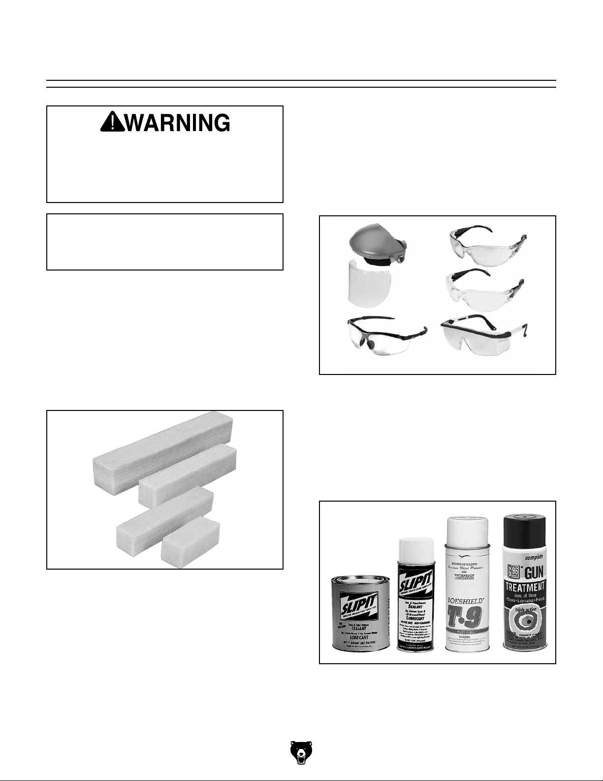
T20501—Face Shield Crown Protector 4"
T20502—Face Shield Crown Protector 7"
T20503—Face Shield Window
T20452—"Kirova" Anti-Reflective S. Glasses
T20451—"Kirova" Clear Safety Glasses
H7194—Bifocal Safety Glasses 1.5
H7195—Bifocal Safety Glasses 2.0
H7196—Bifocal Safety Glasses 2.5
PRO-STIK® Belt Cleaners
3
W1304—1
W1305—1
⁄8" x 41⁄4"
3
⁄8" x 81⁄2"
W1306 —Small (2" x 2" x 12")
1
W1307—Large (1
⁄2" x 11⁄2" x 81⁄2")
These crepe-rubber belt cleaners quickly remove
gum and grit from belts, sleeves, and discs without damage. Extend the life of your belts, sleeves,
or discs with this innovative natural cleaner.
Figure 18. Sanding Sleeve cleaners.
Figure 19. Eye protection.
Machine Lubricants
G5562—SLIPIT
G5563—SLIPIT
®
1 Qt. Gel
®
12 oz Spray
G2871—Boeshield
G2870—Boeshield
®
H3788—G96
H3789—G96
Gun Treatment 12 oz Spray
®
Gun Treatment 4.5 oz Spray
®
T-9 12 oz Spray
®
T-9 4 oz Spray
Figure 20. Recommended products for protect-
ing unpainted cast iron/steel parts on machinery.
-24-
Model T26417/T26418 (Mfd. Since 11/13)
Page 27

Grizzly offers a wide variety of rigid aluminum
oxide sanding sleeves that are perfect for use with
popular sanding drum kits.
Figure 21. 3-pack of hard sanding sleeves.
MODEL SIZE GRIT
H5435
H5436
H5437
H5438
H5439
H5440
H5441
H5442
H5443
H5444
H6674
H6675
H6676
H6677
H6678
D1490
D1491
D1492
D1493
D1494
¾" x 4½"
¾" x 4½"
¾" x 4½"
¾" x 4½"
¾" x 4½"
1" x 4½"
1" x 4½"
1" x 4½"
1" x 4½"
1" x 4½"
2" x 5½"
2" x 5½"
2" x 5½"
2" x 5½"
2" x 5½"
2" x 9"
2" x 9"
2" x 9"
2" x 9"
2" x 9"
60
80
100
120
150
60
80
100
120
150
60
80
100
120
150
60
80
100
120
150
H3632—Respirator Facepiece
H3635—Particulate Aerosol Cartridges, 2 pk.
This lightweight elastomeric facepiece has cradle
suspension, easy adjust headstraps and low
profile for greater field of vision and compatibility
with normal use of glasses or goggles. Purchase
cartridges separately depending upon intended
application.
Figure 22. Medium sized respirator.
G1163—1HP Floor Model Dust Collector
G0710—1HP Wall-Mount Dust Collector
G3591—30 Micron Replacement Bag
H4340—3.0 Micron Upgrade Bag
Excellent point-of-use dust collectors that can
be used next to the machine with only a small
amount of ducting. Specifications: 450 CFM, 7.2"
static pressure, 2 cubic foot bag, and 30 micron
filter. Motor is 1HP, 110V/220V, 14A/7A.
Model G0710
Model G1163
Figure 23. Point-of-use dust collectors.
Model T26417/T26418 (Mfd. Since 11/13)
-25-
Page 28

SECTION 6: MAINTENANCE
accidental startup, always
disconnect machine from
Lubrication
To reduce risk of shock or
The bearings in the motor are shielded, perma-
power before adjustments,
maintenance, or service.
Schedule
nently lubricated and require no maintenance.
Every month, the table tilt assembly should be
cleaned and greased to prevent corrosion and
keep the table moving freely.
To lubricate table tilt assembly:
For optimum performance from your machine,
follow this maintenance schedule and refer to any
specific instructions given in this section.
Daily Check:
• Loose mounting bolts.
• Sanding drums and sleeves for wear or damage.
• Worn or damaged wires.
• Any other unsafe condition.
Cleaning
Cleaning Model T26417/T26418 is relatively easy.
Vacuum excess wood chips and sawdust, and
wipe off the remaining dust with a dry cloth. If any
resin has built up, use a resin dissolving cleaner
to remove it. Treat all unpainted cast iron and steel
with a non-staining lubricant after cleaning, such
as G96
T-9.
®
Gun Treatment, SLIPIT®, or Boeshield®
1. DISCONNECT SANDER FROM POWER!
2. Thoroughly clean lubrication areas of any
grease and dust.
3. Apply a fresh light layer of multipurpose
grease to areas indicated in Figure 24–25
and to corresponding areas on other side of
table tilt assembly. Tilt table several times to
disperse grease.
Lubrication
Points
Figure 24. Lubrication points.
-26-
Lubrication
Points
Figure 25. Scale side lubrication points.
Model T26417/T26418 (Mfd. Since 11/13)
Page 29

Review the troubleshooting and procedures in this section if a problem develops with your machine. If you
need replacement parts or additional help with a procedure, call our Technical Support at (570) 546-9663.
Note: Please gather the serial number and manufacture date of your machine before calling.
SECTION 7: SERVICE
Troubleshooting
Symptom Possible Cause Possible Solution
Motor will not start;
fuses or circuit
breakers blow.
Motor stalls
(resulting in blown
fuses or tripped
circuit).
Deep sanding
grooves or scars in
workpiece.
Grains rub off the
sanding sleeve.
Sanding surfaces
clog quickly or burn.
Burn marks on
workpiece.
1. Switch disabling key removed.
2. Loose connections at motor or switch.
3. Switch, bridge rectifier or motor at fault.
1. Motor overloaded. 1. Reduce feeding pressure.
1. Sanding sleeve too coarse for the desired
finish.
2. Workpiece sanded across the grain.
3. Too much feeding pressure against
workpiece.
1. Sanding sleeve has been stored in an
incorrect environment.
2. Sanding sleeve has been folded or
smashed.
1. Too much pressure against sleeve.
2. Sanding softwood or wood with a high sap
content.
1. Using too fine of sanding grit.
2. Using too much pressure.
3. Work held still for too long.
1. Insert key to enable switch.
2. Inspect all motor connections for loose or open
connections.
3. Replace the component at fault.
1. Use a finer grit sanding sleeve.
2. Sand with the grain.
3. Reduce pressure on workpiece while sanding.
1. Store sanding sleeve away from extremely dry or
hot temperatures.
2. Store sanding sleeves separately and not folded or
flat.
1. Reduce pressure on workpiece while sanding.
2. Either use different wood or plan on cleaning/
replacing sleeves frequently.
1. Use a coarser grit sanding sleeve.
2. Reduce pressure on workpiece while sanding.
3. Do not keep workpiece in one place for too long.
Model T26417/T26418 (Mfd. Since 11/13)
-27-
Page 30

These pages are current at the time of printing. However, in the spirit of improvement, we may make changes to the electrical systems of future machines. Compare the manufacture date of your machine to the one
number and manufacture date of your
machine before calling. This information can be found on the main machine label.
machine
SECTION 8: WIRING
stated in this manual, and study this section carefully.
If there are differences between your machine and what is shown in this section, call Technical Support at
(570) 546-9663 for assistance BEFORE making any changes to the wiring on your machine. An updated
wiring diagram may be available. Note: Please gather the serial
Wiring Safety Instructions
SHOCK HAZARD. Working on wiring that is connected to a power source is extremely dangerous.
Touching electrified parts will result in personal
injury including but not limited to severe burns,
electrocution, or death. Disconnect the power
from the machine before servicing electrical components!
MODIFICATIONS. Modifying the wiring beyond
what is shown in the diagram may lead to unpredictable results, including serious injury or fire.
This includes the installation of unapproved aftermarket parts.
WIRE CONNECTIONS. All connections must
be tight to prevent wires from loosening during
machine operation. Double-check all wires disconnected or connected during any wiring task to
ensure tight connections.
CIRCUIT REQUIREMENTS. You MUST follow
the requirements at the beginning of this manual when connecting your machine to a power
source.
WIRE/COMPONENT DAMAGE. Damaged wires
or components increase the risk of serious personal injury, fire, or machine damage. If you notice
that any wires or components are damaged while
performing a wiring task, replace those wires or
components.
MOTOR WIRING. The motor wiring shown in
these diagrams is current at the time of printing
but may not match your machine. If you find this
to be the case, use the wiring diagram inside the
motor junction box.
CAPACITORS/INVERTERS. Some capacitors
and power inverters store an electrical charge for
up to 10 minutes after being disconnected from
the power source. To reduce the risk of being
shocked, wait at least this long before working on
capacitors.
EXPERIENCING DIFFICULTIES. If you are experiencing difficulties understanding the information
included in this section, contact our Technical
Support at (570) 546-9663.
The photos and diagrams
included in this section are
best viewed in color. You
can view these pages in
color at www.grizzly.com.
-28-
Model T26417/T26418 (Mfd. Since 11/13)
Page 31

T26417 Wiring Diagram
MOTOR 110V
110 VAC
5-15 Plug
(Prewired)
Hot
Neutral
Ground
Gnd
Start
Capacitor
24MFD
300VAC
See
Figure
27
Gnd
PADDLE SWITCH
(Viewed from Behind)
See
Figure
26
Figure 26. T26417 switch connections. Figure 27. T26417 capacitor connections.
Model T26417/T26418 (Mfd. Since 11/13)
READ ELECTRICAL SAFETY
ON PAGE 26!
-29-
Page 32

T26418 Wiring Diagram
PADDLE SWITCH
(Viewed from Behind)
Neutral
Hot
Ground
110 VAC
5-15 Plug
(Prewired)
MOTOR 110V
Gnd
Gnd
Start
Capacitor
45MFD
300VAC
See
Figure
29
See
Figure
28
Figure 28. T26418 switch connection.
-30-
READ ELECTRICAL SAFETY
ON PAGE 26!
Figure 29. T26418 motor connections.
Model T26417/T26418 (Mfd. Since 11/13)
Page 33

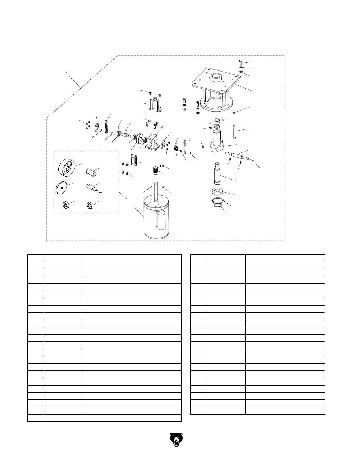
SECTION 9: PARTS
Please Note: We do our best to stock replacement parts whenever possible, but we cannot guarantee that all parts shown here
are available for purchase. Call (800) 523 - 4777 or visit our online parts store at www.grizzly.com to check for availability.
T26417 Main
35
22
31
59
60
61
41
37
21
9
14
34
14
66
19
17
7
3
26
28
68
18
67
35
25
6
53
54
18
67
43
27
16
37
44
21
38
22
45
10
12
13
48
57
58
63
65
23
5
46
55
56
47
140
17
2
8
11
14
67
1
14
66
39
36
14
42
15
40
20
24
49
4
62
67
51
50
52
19
33
Model T26417/T26418 (Mfd. Since 11/13)
-31-
Page 34

T26417 Main
REF PART # DESCRIPTION REF PART # DESCRIPTION
1 PT26417001 STAND 37 PT26417037 STEP BOLT M6-1 X 10
2 PT26417002 TABLE BRACKET (RH) 38 PT26417038 PHLP HD SCR M5-.8 X 6
3 PT26417003 TABLE BRACKET (LH) 39 PT26417039 HEX BOLT M6-1 X 10
4 PT26417004 GRIZZLY SAFETY PADDLE SWITCH 40 PT26417040 HEX NUT M5-.8
5 PT26417005 WORK TABLE 41 PT26417041 ROLL PIN 2.5 X 20
6 PT26417006 SPINDLE 10MM X 3-1/2" 42 PT26417042 STRAIN RELIEF M18 LT
7 PT26417007 TILT BRACKET (LH) 43 PT26417043 KEY 5 X 5 X 50
8 PT26417008 TILT BRACKET (RH) 44 PT26417044 HEX NUT M8-1.25 LH
9 PT26417009 ADJUSTABLE HANDLE M6-1 X 10 45 PT26417045 FLAT WASHER 8MM
10 PT26417010 TILT GEAR 21T 46 PT26417046 SANDING DRUM 3/4" X 3-1/2" (RUBBER)
11 PT26417011 TILT RACK 47 PT26417047 FLAT WASHER 3/8
12 PT26417012 LOCKING THUMBWHEEL 48 PT26417048 SANDING SLEEVE 3/4" X 3-1/2" 100-GRIT
13 PT26417013 TILT SHAFT 49 PT26417049 HEX NUT M8-1.25
14 PT26417014 FLAT WASHER 6MM 50 PT26417050 FOOT (RUBBER)
15 PT26417015 FLAT WASHER 5MM 51 PT26417051 FLAT WASHER 8MM
16 PT26417016 HEX BOLT M6-1 X 12 52 PT26417052 HEX BOLT M8-1.25 X 25
17 PT26417017 HEX BOLT M8-1.25 X 16 53 PT26417053 SPINDLE 10MM X 4-1/2"
18 PT26417018 HEX BOLT M8-1.25 X 20 54 PT26417054 SPINDLE 16MM X 5-1/2"
19 PT26417019 HEX BOLT M6-1 X 16 55 PT26417055 SANDING DRUM 1" X 4-1/2" (RUBBER)
20 PT26417020 HEX BOLT M5-.8 X 16 56 PT26417056 SANDING DRUM 2" X 5-1/2" (RUBBER)
21 PT26417021 ECCENTRIC SPACER 57 PT26417057 SANDING SLEEVE 1" X 4-1/2" 100-GRIT
22 PT26417022 FLAT HD SCR M6-1 X 10 58 PT26417058 SANDING SLEEVE 2" X 5-1/2" 100-GRIT
23 PT26417023 TILT HANDLE 59 PT26417059 TABLE INSERT 2-3/8" ID
24 PT26417024 DRUM STORAGE RACK 60 PT26417060 TABLE INSERT 1-1/4" X 2-1/8" ID
25 PT26417025 DUST DEFLECTOR (LOWER) 61 PT26417061 TABLE INSERT 2-3/8" X 3-5/8" ID
26 PT26417026 DUST DEFLECTOR (UPPER) 62 PT26417062 SWITCH BOX COVER
27 PT26417027 OSCILLATOR ASSEMBLY 63 PT26417063 WRENCH 14 X 17MM OPEN-ENDS
28 PT26417028 DUST COLLECTION CHUTE 65 PT26417065 HEX NUT M10-1.5
31 PT26417031 TABLE INSERT 1-1/4" ID 66 PT26417066 LOCK WASHER 6MM
33 PT26417033 TABLE INSERT STORAGE RACK 67 PT26417067 FLAT WASHER 8MM
34 PT26417034 ANGLE INDICATOR 68 PT26417068 PHLP HD SCR M6-1 X 12
35 PT26417035 PHLP HD SCR M5-.8 X 8 140 PT26417140 FLAT WASHER 5/8
36 PT26417036 PHLP HD SCR M4-.7 X 12
-32-
Model T26417/T26418 (Mfd. Since 11/13)
Page 35
27
T26417 Oscillator Assembly
126
129
128
124
116-2
116-5
131
116-1
107
108
111
116-3
116-4
116-6
109
137
112
110
116
125
138
106
125
114
135
112
127
115
104
124
113
107
118
121
137
109
111
108
117
131
132
130
139
122
136
117
122
133
134
103
102
101
120
119
123
130
REF PART # DESCRIPTION REF PART # DESCRIPTION
27 PT26417027 OSCILLATOR ASSEMBLY 118 PT26417118 SET SCREW M6-1 X 6 DOG-PT
101 PT26417101 MOTOR MOUNT 119 PT26417119 HEX BOLT M8-1.25 X 75
102 PT26417102 SPINDLE BASE 120 PT26417120 HEX NUT M8-1.25 THIN
103 PT26417103 QUILL 121 PT26417121 KEY 5 X 5 X 50
104 PT26417104 OSCILLATOR BRACKET 122 PT26417122 LOCK WASHER 5MM
106 PT26417106 OSCILLATOR SHAFT 123 PT26417123 SWING ARM SHAFT
107 PT26417107 END PLATE 124 PT26417124 FLAT HD SCR M4-.7 X 6
108 PT26417108 CRANK SHAFT 125 PT26417125 PHLP HD SCR M5-.8 X 8
109 PT26417109 ECCENTRIC LOCK COLLAR 126 PT26417126 HEX BOLT M8-1.25 X 20
110 PT26417110 WORM WHEEL 127 PT26417127 HEX BOLT M6-1 X 16
111 PT26417111 SWING ARM 128 PT26417128 FLAT WASHER 8MM
112 PT26417112 BALL BEARING 6001ZZ 129 PT26417129 LOCK WASHER 8MM
113 PT26417113 WORM 130 PT26417130 LOCK NUT M5-.8
114 PT26417114 WORM COVER 131 PT26417131 E-CLIP 5MM
115 PT26417115 BRACKET FRONT PLATE 132 PT26417132 BALL BEARING 6904ZZ
116 PT26417116 MOTOR 1/2HP 110V 1-PH 133 PT26417133 BALL BEARING 6006ZZ
116-1 PT26417116-1 MOTOR FAN COVER 134 PT26417134 INT RETAINING RING 55MM
116-2 PT26417116-2 MOTOR FAN 135 PT26417135 FLAT HD SCR M4-.7 X 10
116-3 PT26417116-3 CAPACITOR COVER 136 PT26417136 EXT RETAINING RING 30MM
116-4 PT26417116-4 S CAPACITOR 24M 300V 35 X 72MM 137 PT26417137 SET SCREW M5-.8 X 6 DOG-PT
116-5 PT26417116-5 BALL BEARING 6203ZZ 138 PT26417138 KEY 4 X 4 X 12
116-6 PT26417116-6 BALL BEARING 6202ZZ 139 PT26417139 QUILL DUST SEAL
117 PT26417117 SET SCREW M6-1 X 6 DOG-PT
Model T26417/T26418 (Mfd. Since 11/13)
-33-
Page 36

T26417 Machine Labels & Cosmetics
208
201
207
206
205
204
203
REF PART # DESCRIPTION REF PART # DESCRIPTION
201 PT26417201 MACHINE ID LABEL 205 PT26417205 READ MANUAL LABEL
202 PT26417202 MODEL NUMBER LABEL 206 PT26417206 EYE/LUNG HAZARD LABEL
203 PT26417203 GRIZZLY.COM LABEL 207 PT26417207 GRIZZLY GREEN TOUCH-UP PAINT
204 PT26417204 ENTANGLEMENT HAZARD LABEL 208 PT26417208 DISCONNECT WARNING LABEL
202
Safety labels help reduce the risk of serious injury caused by machine hazards. If any label comes
off or becomes unreadable, the owner of this machine MUST replace it in the original location
before resuming operations. For replacements, contact (800) 523-4777 or www.grizzly.com.
-34-
Model T26417/T26418 (Mfd. Since 11/13)
Page 37

T26418 Main
Please Note: We do our best to stock replacement parts whenever possible, but we cannot guarantee that all parts shown here
are available for purchase. Call (800) 523 - 4777 or visit our online parts store at www.grizzly.com to check for availability.
54
23
47
15
51
48
12
24
19
23
44
51
59
26
22
36
1
22
14
22
17
35
16
28
42
4
31
41
61
23
5
25
40
13
59
22
28
16
17
6
22
62
63
64
65
2
35
3
11
27
56
58
70
71
57
67
53
66
14
36
21
9
10
32
8
33
55
68
69
60
72
20
23
46
7
20
23
30
29
18
49
38
52
43
37
24
37
Model T26417/T26418 (Mfd. Since 11/13)
23
16
-35-
Page 38

T26418 Main
REF PART # DESCRIPTION REF PART # DESCRIPTION
1 PT26418001 TILT BRACKET (LH) 36 PT26418036 FLAT HD SCR M6-1 X 12
2 PT26418002 TILT BRACKET (RH) 37 PT26418037 HEX NUT M5-.8
3 PT26418003 ANGLE RACK 38 PT26418038 STAND FRONT PANEL
4 PT26418004 WORK TABLE 40 PT26418040 DUST COLLECTION CHUTE
5 PT26418005 TABLE BRACKET (LH) 41 PT26418041 TABLE INSERT 1-1/4" ID
6 PT26418006 TABLE BRACKET (RH) 42 PT26418042 DRUM STORAGE RACK
7 PT26418007 GRIZZLY SAFETY PADDLE SWITCH 43 PT26418043 PHLP HD SCR M5-.8 X 12
8 PT26418008 TILT HANDLE 44 PT26418044 OSCILLATOR ASSEMBLY MOUNT
9 PT26418009 TILT SHAFT 46 PT26418046 TABLE INSERT STORAGE RACK
10 PT26418010 LOCKING THUMBWHEEL 47 PT26418047 SQUARE CUSHION (RUBBER)
11 PT26418011 TILT GEAR 21T 48 PT26418048 PHLP HD SCR M5-.8 X 25
12 PT26418012 DUST DEFLECTOR (LOWER) 49 PT26418049 PHLP HD SCR M6-1 X 14
13 PT26418013 DUST DEFLECTOR (UPPER) 51 PT26418051 HEX BOLT M8-1.25 X 40
14 PT26418014 ECCENTRIC SPACER 52 PT26418052 CUSHION (RUBBER)
15 PT26418015 OSCILLATOR ASSEMBLY 53 PT26418053 SPINDLE 10MM X 4-1/2"
16 PT26418016 HEX BOLT M8-1.25 X 16 54 PT26418054 HEX NUT M10-1.5 LH
17 PT26418017 HEX BOLT M6-1 X 16 55 PT26418055 SANDING SLEEVE 3/4" X 4-1/2" 100-GRIT
18 PT26418018 HEX BOLT M8-1.25 X 25 56 PT26418056 FLAT WASHER 8MM
19 PT26418019 PHLP HD SCR M6-1 X 10 57 PT26418057 FLAT WASHER 3/8
20 PT26418020 HEX NUT M8-1.25 58 PT26418058 SANDING DRUM 3/4" X 4-1/2" (RUBBER)
21 PT26418021 FLAT HD SCR M5-.8 X 6 59 PT26418059 HEX BOLT M6-1 X 12
22 PT26418022 FLAT WASHER 6MM 60 PT26418060 KEY 5 X 5 X 50
23 PT26418023 FLAT WASHER 8MM 61 PT26418061 TABLE INSERT 1-1/4" X 2-1/8" ID
24 PT26418024 FLAT WASHER 5MM 62 PT26418062 TABLE INSERT 2-3/8" ID
25 PT26418025 HEX BOLT M5-.8 X 8 63 PT26418063 TABLE INSERT 2-3/8" X 3-5/8" ID
26 PT26418026 ADJUSTABLE HANDLE M6-1 X 10 64 PT26418064 TABLE INSERT 3-1/2" ID
27 PT26418027 STAND 65 PT26418065 TABLE INSERT 3-1/2" X 4-1/2" ID
28 PT26418028 LOCK WASHER 6MM 66 PT26418066 SPINDLE 16MM X 9"
29 PT26418029 FOOT (RUBBER) 67 PT26418067 FLAT WASHER 5/8
30 PT26418030 HEX NUT M8-1.25 68 PT26418068 SANDING SLEEVE 2" X 9" 100-GRIT
31 PT26418031 ROLL PIN 2.5 X 12 69 PT26418069 SANDING SLEEVE 3" X 9" 100-GRIT
32 PT26418032 HEX NUT M5-.8 THIN 70 PT26418070 SANDING DRUM 2" X 9" (RUBBER)
33 PT26418033 BASE 71 PT26418071 SANDING DRUM 3" X 9" (RUBBER)
35 PT26418035 STEP BOLT M6-1 X 10 72 PT26418072 WRENCH 19 X 22MM OPEN-ENDS
-36-
Model T26417/T26418 (Mfd. Since 11/13)
Page 39

15
T26418 Oscillator Assembly
126
129
128
107
124
131
108
116-1
116-2
116-3
116-4
116-5 116-6
111
109
137
112
138
110
116
125
114
106
140
125
127
112
135
115
104
124
113
107
118
121
137
109
108
111
117
131
132
130
139
122
136
117
122
133
134
103
102
101
120
119
123
130
REF PART # DESCRIPTION REF PART # DESCRIPTION
15 PT26418015 OSCILLATOR ASSEMBLY 118 PT26418118 SET SCREW M6-1 X 6 DOG-PT
101 PT26418101 MOTOR MOUNT 119 PT26418119 HEX BOLT M8-1.25 X 85
102 PT26418102 SPINDLE BASE 120 PT26418120 HEX NUT M8-1.25 THIN
103 PT26418103 QUILL 121 PT26418121 KEY 6 X 6 X 50
104 PT26418104 OSCILLATOR BRACKET 122 PT26418122 LOCK WASHER 5MM
106 PT26418106 OSCILLATOR SHAFT 123 PT26418123 SWING ARM SHAFT
107 PT26418107 END PLATE 124 PT26418124 FLAT HD SCR M4-.7 X 6
108 PT26418108 CRANK SHAFT 125 PT26418125 PHLP HD SCR M5-.8 X 8
109 PT26418109 ECCENTRIC LOCK COLLAR 126 PT26418126 HEX BOLT M8-1.25 X 20
110 PT26418110 WORM WHEEL 127 PT26418127 HEX BOLT M6-1 X 16
111 PT26418111 SWING ARM 128 PT26418128 FLAT WASHER 8MM
112 PT26418112 BALL BEARING 6001ZZ 129 PT26418129 LOCK WASHER 8MM
113 PT26418113 WORM 130 PT26418130 LOCK NUT M5-.8
114 PT26418114 WORM COVER 131 PT26418131 E-CLIP 5MM
115 PT26418115 BRACKET FRONT PLATE 132 PT26418132 BALL BEARING 6805ZZ
116 PT26418116 MOTOR 1HP 110V 1-PH 133 PT26418133 BALL BEARING 6007ZZ
116-1 PT26418116-1 MOTOR FAN COVER 134 PT26418134 INT RETAINING RING 62MM
116-2 PT26418116-2 MOTOR FAN 135 PT26418135 FLAT HD SCR M4-.7 X 16
116-3 PT26418116-3 JUNCTION BOX W/COVER 136 PT26418136 EXT RETAINING RING 35MM
116-4 PT26418116-4 S CAPACITOR 45M 300V 44 X 80MM 137 PT26418137 SET SCREW M5-.8 X 6 DOG-PT
116-5 PT26418116-5 BALL BEARING 6204ZZ 138 PT26418138 KEY 4 X 4 X 12
116-6 PT26418116-6 BALL BEARING 6205ZZ 139 PT26418139 QUILL DUST SEAL
117 PT26418117 SET SCREW M6-1 X 6 DOG-PT 140 PT26418140 PHLP HD SCR M4-.7 X 8
Model T26417/T26418 (Mfd. Since 11/13)
-37-
Page 40

T26418 Machine Labels & Cosmetics
201
208
207
206
202
205
203
204
REF PART # DESCRIPTION REF PART # DESCRIPTION
201 PT26418201 MACHINE ID LABEL 205 PT26418205 DISCONNECT WARNING LABEL
202 PT26418202 GRIZZLY GREEN TOUCH-UP PAINT 206 PT26418206 EYE/LUNG HAZARD LABEL
203 PT26418203 GRIZZLY.COM LABEL 207 PT26418207 MODEL NUMBER LABEL
204 PT26418204 ENTANGLEMENT HAZARD LABEL 208 PT26418208 READ MANUAL LABEL
Safety labels help reduce the risk of serious injury caused by machine hazards. If any label comes
off or becomes unreadable, the owner of this machine MUST replace it in the original location
before resuming operations. For replacements, contact (800) 523-4777 or www.grizzly.com.
-38-
Model T26417/T26418 (Mfd. Since 11/13)
Page 41

WARRANTY CARD
Name _____________________________________________________________________________
Street _____________________________________________________________________________
City _______________________ State _________________________ Zip _____________________
Phone # ____________________ Email _________________________________________________
Model # ____________________ Order # _______________________ Serial # __________________
The following information is given on a voluntary basis. It will be used for marketing purposes to help us develop
better products and services. Of course, all information is strictly confidential.
1. How did you learn about us?
____ Advertisement ____ Friend ____ Catalog
____ Card Deck ____ Website ____ Other:
2. Which of the following magazines do you subscribe to?
____ Cabinetmaker & FDM
____ Family Handyman
____ Hand Loader
____ Handy
____ Home Shop Machinist
____ Journal of Light Cont.
____ Live Steam
____ Model Airplane News
____ Old House Journal
____ Popular Mechanics
3. What is your annual household income?
____ $20,000-$29,000 ____ $30,000-$39,000 ____ $40,000-$49,000
____ $50,000-$59,000 ____ $60,000-$69,000 ____ $70,000+
CUT ALONG DOTTED LINE
4. What is your age group?
____ 20-29 ____ 30-39 ____ 40-49
____ 50-59 ____ 60-69 ____ 70+
5. How long have you been a woodworker/metalworker?
____ 0-2 Years ____ 2-8 Years ____ 8-20 Years ____20+ Years
6. How many of your machines or tools are Grizzly?
____ 0-2 ____ 3-5 ____ 6-9 ____10+
____ Popular Science
____ Popular Woodworking
____ Precision Shooter
____ Projects in Metal
____ RC Modeler
____ Rie
____ Shop Notes
____ Shotgun News
____ Today’s Homeowner
____ Wood
____ Wooden Boat
____ Woodshop News
____ Woodsmith
____ Woodwork
____ Woodworker West
____ Woodworker’s Journal
____ Other:
7. Do you think your machine represents a good value? _____Yes _____No
8. Would you recommend Grizzly Industrial to a friend? _____ Yes _____No
9. Would you allow us to use your name as a reference for Grizzly customers in your area?
Note: We never use names more than 3 times. _____Yes _____No
10. Comments: _____________________________________________________________________
_________________________________________________________________________________
_________________________________________________________________________________
_________________________________________________________________________________
Page 42

FOLD ALONG DOTTED LINE
FOLD ALONG DOTTED LINE
Place
Stamp
Here
GRIZZLY INDUSTRIAL, INC.
P.O. BOX 2069
BELLINGHAM, WA 98227-2069
Send a Grizzly Catalog to a friend:
Name_______________________________
Street_______________________________
City______________State______Zip______
TAPE ALONG EDGES--PLEASE DO NOT STAPLE
Page 43

WARRANTY & RETURNS
Grizzly Industrial, Inc. warrants every product it sells for a period of 1 year to the original purchaser from
the date of purchase. This warranty does not apply to defects due directly or indirectly to misuse, abuse,
negligence, accidents, repairs or alterations or lack of maintenance. This is Grizzly’s sole written warranty
and any and all warranties that may be implied by law, including any merchantability or fitness, for any particular purpose, are hereby limited to the duration of this written warranty. We do not warrant or represent
that the merchandise complies with the provisions of any law or acts unless the manufacturer so warrants.
In no event shall Grizzly’s liability under this warranty exceed the purchase price paid for the product and
any legal actions brought against Grizzly shall be tried in the State of Washington, County of Whatcom.
We shall in no event be liable for death, injuries to persons or property or for incidental, contingent, special,
or consequential damages arising from the use of our products.
To take advantage of this warranty, contact us by mail or phone and give us all the details. We will then issue
you a “Return Number,’’ which must be clearly posted on the outside as well as the inside of the carton. We
will not accept any item back without this number. Proof of purchase must accompany the merchandise.
The manufacturers reserve the right to change specifications at any time because they constantly strive to
achieve better quality equipment. We make every effort to ensure that our products meet high quality and
durability standards and we hope you never need to use this warranty.
Please feel free to write or call us if you have any questions about the machine or the manual.
Thank you again for your business and continued support. We hope to serve you again soon.
Page 44

 Loading...