

Page 1

MODELS T10502, T10556,
& T26300
TAPER ATTACHMENT
INSTRUCTIONS
For questions or help with this product contact Tech Support at (570) 546-9663 or techsupport@grizzly.com
Introduction
This taper attachment provides precision outside
and inside tapers up to 12" without having to offset the tailstock.
Another feature is the ability to use the attachment without disengaging the cross slide. This
allows the taper attachment to be functional at any
time by simply tightening the bed clamp bracket.
However, the taper attachment does not interfere
with other turning operations.
This taper attachment features scales at both
ends, reading inches-of-taper per foot and angle
of taper. An adjustment knob with fine threads
achieves precise control when setting tapers.
Identification
A
E
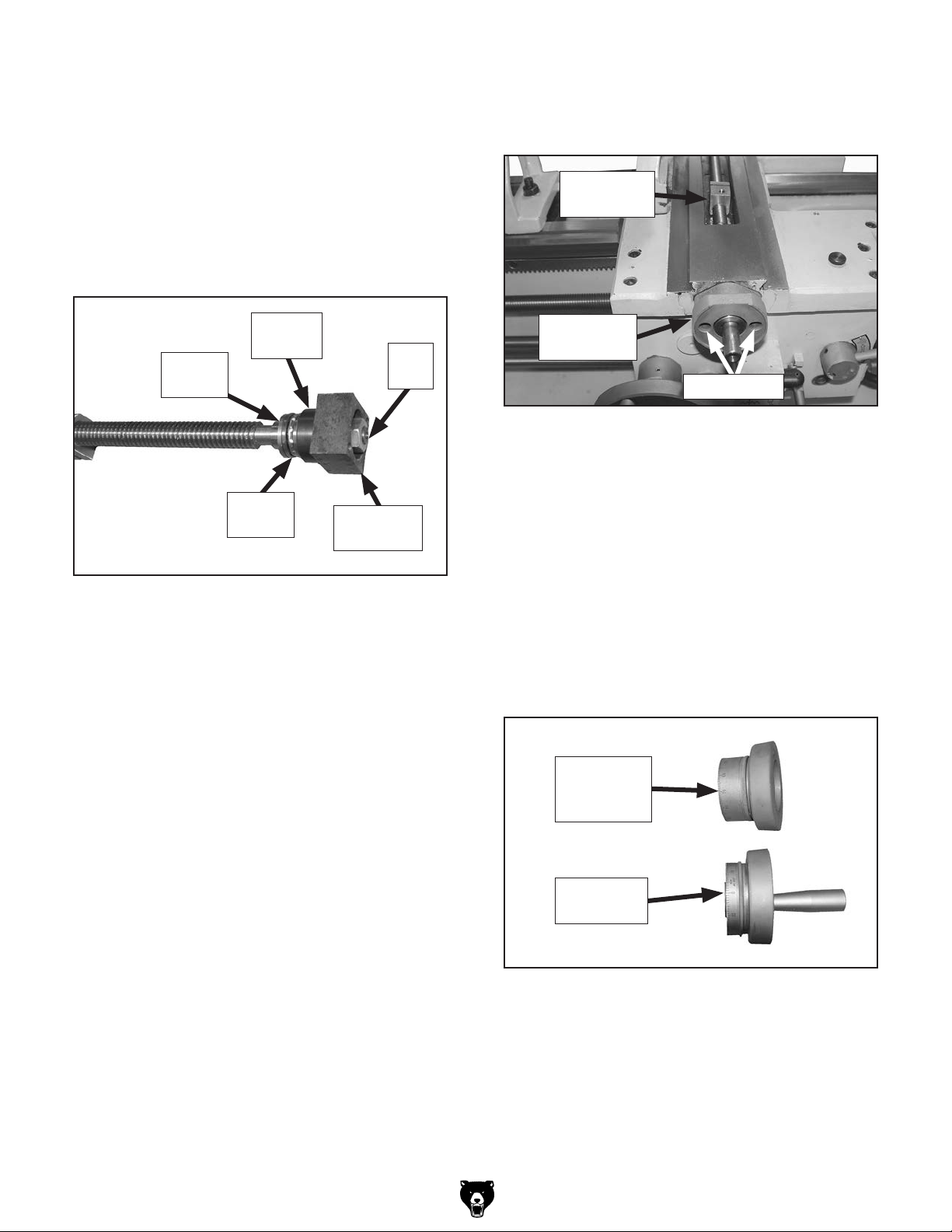
B. Slide Table: Connects to the bed clamp and
provides a stable platform for the pivot bar.
C. Body: Houses the pivot and slide blocks that
connect to the cross slide.
D. Taper Adjustment Knob: Adjusts the angle
of the pivot bar for the desired taper.
E. Pivot Bar: Provides an angled dovetail path
to guide the tooling for the desired taper.
Specifications
Model T10556 ...... for G4002, G4003, & G4003G
Model T10502 .......................................for G0709
Model T26300 ................................... for G0750G
Maximum Taper Length .................................... 9"
Taper Per Inch Range ..............................0"– ±3"
Inch Scale Divisions ........................................
Taper Angle Range ..................................0°– ±5°
Angle Scale Divisions ....................................... 1°
Construction ................................ Cast Iron, Steel
Shipping Weight ........................................60 lbs.
1
⁄2 "
B
C
Figure 1. Taper attachment identification.
A. Bed Clamp: Secures the taper attachment
to a specific position on the bedway and
enables the use of the taper attachment.
COPYRIGHT © JULY, 2013 BY GRIZZLY INDUSTRIAL, INC. REVISED JANUARY, 2018 (HE)
NO PORTION OF THIS MANUAL MAY BE REPRODUCED IN ANY SHAPE
OR FORM WITHOUT THE WRITTEN APPROVAL OF GRIZZLY INDUSTRIAL, INC.
FOR MODELS MANUFACTURED SINCE 3/13 #TS15756 PRINTED IN CHINA
D
This taper attachment is heavy! Get
assistance when installing it on the lathe.
To reduce the risk of crushing injuries, wear
boots with toe protection and keep hands
and fingers away from all pinch points.
Page 2

Inventory
This taper attachment was carefully packed when
it left our warehouse. If you discover the taper
attachment is damaged after you have signed
for delivery, please immediately call Customer
Service at (800) 523-4777 for advice.
Save the containers and all packing materials for
possible inspection by the carrier or its agent.
Otherwise, filing a freight claim can be difficult.
When you are completely satisfied with the condition of your shipment, you should inventory the
contents.
Box Contents (Figure 2): Qty
A. Slide Table & Body Assembly .....................1
B. Bed Clamp Rod ...........................................1
C. Bed Clamp Pivot Shaft w/Cap Screw ..........1
D. Work Lamp Extension Shaft .......................1
E. Handwheel Handle w/Shoulder Screw ........1
F. Alternate Leadscrew Rear Bracket ..............1
G. Bed Clamp Block w/Cap Screws .................1
H. Bed Clamp Bracket w/Cap Screw ...............1
I. Cross Feed Handwheel & Leadscrew
Assembly .....................................................1
J. Hardware Bag (Not Shown)
— Roll Pins 6 x 30mm ................................ 2
— Cap Screws M8-1.25 x 25 ...................... 2
— Cap Screws M8-1.25 x 16 ...................... 2
— Cap Screw M8-1.25 x 12 ........................ 1
— Cap Screws M6-1 x 25........................... 2
— Cap Screw M6-1 x 14............................. 1
Required for Setup
The items listed below are required to successfully set up and prepare this taper attachment for
operation. The installation is intended to be semipermanent and will take 1–2 hours.
Description Qty
• Another Person ...........................................1
• Safety Glasses .........................1 Per Person
• Cleaner/Degreaser ......................As Needed
• Disposable Shop Rags ................As Needed
• Oil Can w/General Machine Oil ...................1
• Grease NLGI#2 ...........................As Needed
• Drill & Drill Bit
• Bottoming Hand Tap M8-1.25 ......................1
• Precision Ruler ............................................1
• Phillips Screwdriver #0 ................................1
• Phillips Screwdriver #2 ................................1
• Wrench 14mm .............................................1
• Wrench & Socket 17mm .................... 1 Each
• Hex Wrench 2.5mm .....................................1
• Hex Wrench 4mm ........................................1
• Hex Wrench 5mm ........................................1
• Hex Wrench 6mm ........................................1
• Deadblow Hammer ......................................1
9
⁄32" ............................. 1 Each
Assembly & Installation
1. DISCONNECT LATHE FROM POWER!
2. Remove the back splash from the rear of
the lathe by removing the (4) Phillips head
screws and flat washers that secure it.
-2-
A
B
I
H
Figure 2. Shipping inventory.
C
G
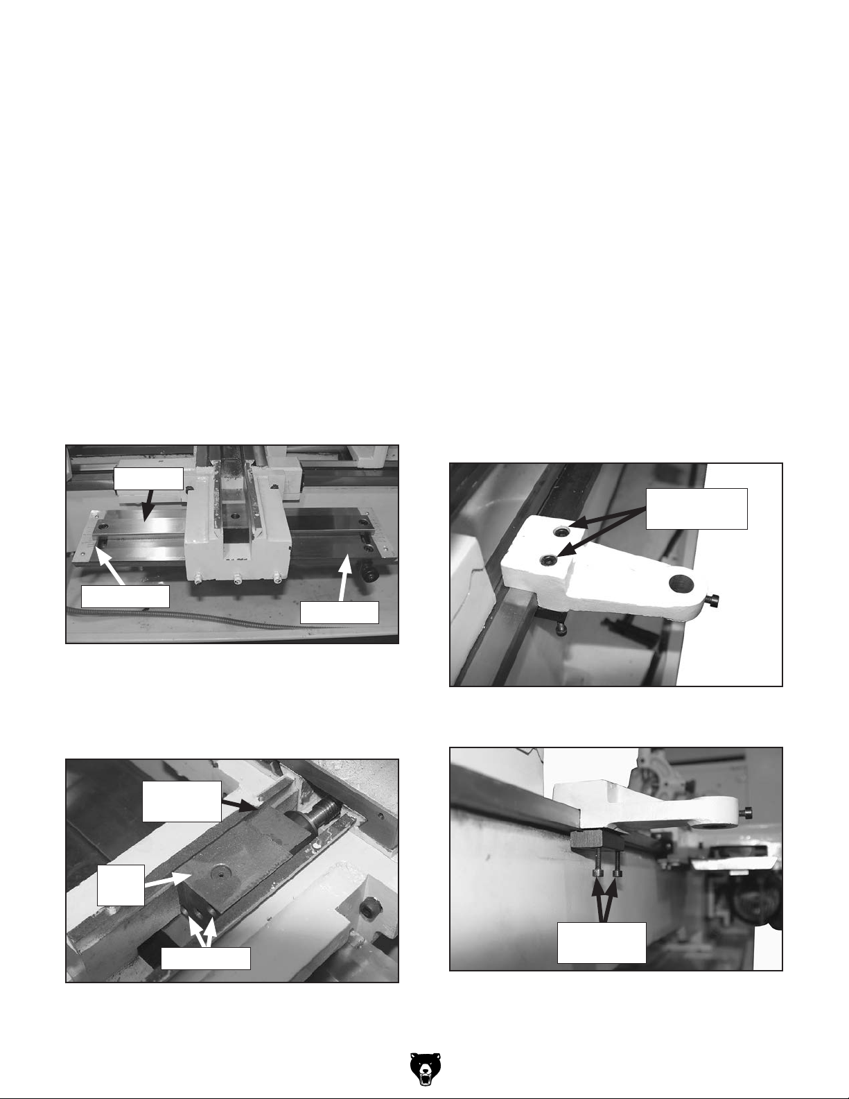
3. Remove the compound rest from the cross
slide by removing the (2) hex nuts shown in
Figure 3.
D
Hex Nuts
E
F
Figure 3. Hex nuts that secure the compound
rest.
T10502, T10556, T26300 (Mfg. Since 3/13)
Page 3

Keep track of fasteners removed. Some will
be needed for re-installing components.
4. Remove the cross slide rear cover by remov-
ing the (2) cap screws shown in Figure 4.
Rear
Cover
6. Rotate the cross slide handwheel clockwise until the leadscrew nut exits the rear
of the cross slide and can be removed (see
Figure 6).
Leadscrew
Nut
Leadscrew
Cap Screws
Figure 4. Cross slide rear cover location.
5. Remove the cap screw shown in Figure 5.
This cap screw secures the cross slide to the
leadscrew nut.
Cap Screw
Installation
Hole
Figure 6. Leadscrew nut removed from cross
slide leadscrew.
7. Loosen the set screw on the cross slide
handwheel retainer (see Figure 7), and rotate
the retainer counterclockwise to unthread
and remove it from the handwheel.
Handwheel
Retainer
Set
Screw
Figure 7. Handwheel retainer set screw location.
Figure 5. Cap screw removed that secures cross
slide to leadscrew nut.
T10502, T10556, T26300 (Mfg. Since 3/13)
-3-
Page 4

8. Slide the handwheel and graduated dial
assembly off the leadscrew, then remove the
two cap screws that secure the handwheel
bracket to the cross slide (see Figure 8).
Handwheel
Bracket
11. Remove the cross slide from the saddle by
sliding it off the dovetail way (see Figure 10).
Cap Screws
Figure 8. Handwheel bracket cap screw
locations.
9. Pull the handwheel bracket and leadscrew
assembly from the front of the cross slide
(see Figure 9).
Leadscrew
Assembly
Figure 9. Cross slide leadscrew assembly
removed.
10. Remove the work lamp and bracket assembly
from the rear of the saddle, and set it aside
for now. It is not necessary to disconnect the
wires at this time.
Figure 10. Cross slide removed from saddle.
12. Remove the top cover from the taper attach-
ment body (see Figure 11), the remove the
block assembly.
Slide
Table
Pivot
Bar
Figure 11. Top cover and block assembly
removed from taper attachment body.
Note: To accomplish this step, you may have
to loosen the block assembly with a deadblow hammer.
13. Slide the taper attachment body off the pivot
bar.
Top Cover
Block
Assembly
Taper Attachment Body
Note: For the Model G0709, the bracket
assembly also includes the coolant nozzle.
-4-
T10502, T10556, T26300 (Mfg. Since 3/13)
Page 5

14. Loosely re-install the top cover on the attachment.
15. Have another person align and hold the body
against the rear of the saddle, then use a
punch to mark the saddle through the attachment holes.
Note: The taper attachment body is properly
aligned when the sides of the internal ways
are evenly aligned with those of the saddle
and the top cover is flush with or slightly
lower than the saddle dovetail ways (see
Figure 12).
19. Loosen the (2) cap screws on the block
assembly you removed from the body in
Step 12, then separate the pivot and alignment blocks, as shown in Figure 13.
Pivot
Block
Alignment Block
Top Flush with Dovetail Ways Here
Attachment Holes
Figure 12. Taper attachment body properly
aligned with saddle.
16. Drill and tap holes at the two marks you made
in Step 15. The tapped holes should accept
M8-1.25 x 25 cap screws.
17. Mount the attachment body to the saddle, as
shown in Figure 12.
18. Remove the top cover from the taper attachment.
Cap Screws
Figure 13. Pivot and alignment blocks
separated.
20. If the alternate leadscrew rear bracket is
installed on the taper attachment leadscrew
(see Figure 14), then remove it now.
Important: Make a note of the order of the
components in front of and behind the bracket, and keep this information for future use.
If you remove the taper attachment later, the
taper attachment leadscrew and handwheel
can remain installed by re-installing the
bracket and the components in the same
order. The bracket is mounted to the saddle
in the same manner as the taper attachment
body.
Taper Attachment
Leadscrew
T10502, T10556, T26300 (Mfg. Since 3/13)
Alternate Leadscrew
Rear Bracket
Figure 14. Alternate leadscrew rear bracket on
taper attachment leadscrew.
-5-
Page 6
21. Keeping the component order on the end of
the taper attachment leadscrew the same as
it was shipped (minus the alternate bracket),
install the alignment block you removed in
Step 20 between the bearing cap and hex
nuts, as shown in Figure 15.
Note: Hand-tighten the first hex nut, then
tighten the second hex nut against the first to
secure the installation.
24. Slide the leadscrew assembly into the saddle
with the threaded hole in the leadscrew nut
facing up, as shown in Figure 16.
Leadscrew
Nut
Bearing
Cap
Flat
Washer
Thrust
Bearing
Figure 15. Alignment block installed on taper
attachment leadscrew.
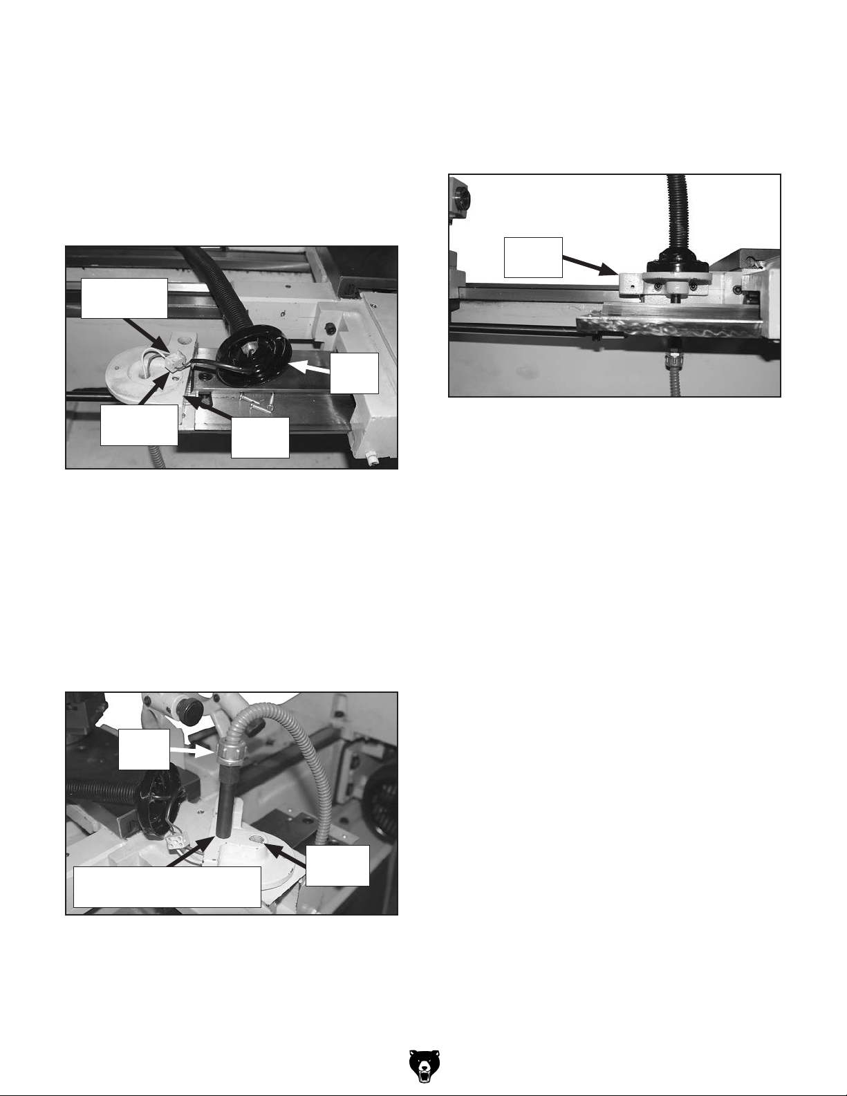
22. Remove the handwheel and graduated dial
from the taper attachment leadscrew assembly in the same manner as instructed in
Steps 7–8.
23. Rotate the alignment block at the end of the
leadscrew (see Figure 15) so the orientation
of the threaded holes will match the orientation of the cap screws in the pivot block when
it is installed inside the taper attachment body
(see to Step 31 and Figure 20 on Page 7 for
orientation reference).
Alignment
Hex
Nuts
Block
Handwheel
Bracket
Cap Screws
Figure 16. Taper attachment leadscrew
assembly installed.
25. Secure the handwheel bracket in place with
(2) M8-1.25 x 16 cap screws.
26. Re-install the handwheel and graduated dial
assembly, then attach the handle.
Note: Be sure to install the handwheel
and graduated dial assembly that came
with the taper attachment. As shown in
Figure 17, there is a critical difference in
thickness between the two.
Taper
Attachment
Handwheel
Original
Handwheel
-6-
Figure 17. Handwheel comparison.
T10502, T10556, T26300 (Mfg. Since 3/13)
Page 7
27. Slide the cross slide back onto the saddle
dovetail.
28. Use the cross slide handwheel to position the
leadscrew nut so the hole in the cross slide
aligns with the threaded hole in the top of the
leadscrew nut.
32. Use the cross slide handwheel to extend the
end of the leadscrew into the taper attachment body so the alignment block is against
the pivot block, as shown in Figure 19.
33. Thread the cap screws through the pivot
block into the alignment block to secure it.
29. Secure the cross slide to the leadscrew nut
with the cap screw removed in Step 5.
Note: Only tighten the cap screw until it is
snug. Overtightening it could interfere with
cross slide movement.
30. Orient the angle scale of the slide table
toward the tailstock, then slide the pivot bar
dovetail through the slide block underneath
the taper attachment body, as shown in
Figure 18.
Pivot Bar
Angle Scale
Slide table
34. Re-install the taper attachment top cover.
35. Attach the bed clamp bracket and bed clamp
block to the bedway between the tailstock
and taper attachment, using (2) M10-1.5 x 30
cap screws and (2) M6-1 x 35 cap screws, as
shown in Figures 20–21. Leave the bracket
loose enough on the bedway so that you
adjust its position.
Note: Use the bottom cap screws to bring the
bracket level with the bedway, then use the
top cap screws to secure the bracket in place.
M10-1.5 x 30
Cap Screws
Figure 18. Slide table re-installed.
31. Re-install the pivot block into the taper attach-
ment body so that you can access the cap
screws from the outside (see Figure 19).
Alignment
Block
Pivot
Block
Cap Screws
Figure 19. Pivot and alignment blocks
re-installed.
Figure 20. Bed clamp bracket and block
attached to bedway (top view).
M6-1 x 35
Cap Screws
Figure 21. Bed clamp bracket and block
attached to bedway (bottom view).
T10502, T10556, T26300 (Mfg. Since 3/13)
-7-
Page 8

36. Attach the flattened end of the bed clamp rod
to the underside of the slide table, as shown
in Figure 22, with (1) M6-1 x 20 cap screw.
Bed Clamp
Rod
40. Mount a dial indicator magnetic base on top
of the saddle so that the indicator needle is
resting on the pivot bar at the tailstock end,
as shown in Figure 24, then zero the indicator.
M6-1 x 20
Cap Screw
Figure 22. Bed clamp rod attached to slide table.
37. Insert the round end of the bed clamp rod
into the bed clamp pivot shaft, then insert the
pivot shaft into the bottom of the bed clamp
bracket, as shown in Figure 23.
Bed Clamp
Pivot Shaft
Bed Clamp Rod
Figure 23. Bed clamp pivot pin installed.
Pivot
Bar
Figure 24. Using a dial indicator to measure
slide table tilt.
41. Move the carriage toward the tailstock as far
as possible.
— If the indicator reading is 0.010" or less, the
tilt of the slide table is considered acceptable. Proceed to Step 36.
— If the indicator reading is greater than
0.010", proceed with the next step.
42. Loosen the cap screws that secure the taper
attachment body to the saddle, then rotate
the taper attachment assembly left or right to
correct the tilt. Retighten the cap screws and
repeat Step 41.
38. Tighten the bed clamp bracket cap screws to
secure it in position on the bedway.
39. Move the carriage toward the spindle as far
as possible.
Note: Adjust components as necessary to
expose as much of the pivot bar as possible
on the tailstock side of the taper attachment
body.
-8-
T10502, T10556, T26300 (Mfg. Since 3/13)
Page 9
43. Separate the lamp base from the lamp bracket, as shown in Figure 25.
Disconnect the wires at the lamp terminal
bar, on the side coming from the electrical
box.
Note: For the Model G0709, the coolant
nozzle position does not need changing.
Disconnect
Wires Here
Lamp
Base
46. Reconnect the wires to the lamp terminal bar,
re-attach the lamp base to the lamp bracket,
then re-attach the bracket to the saddle using
the (2) M6-1 x 10 cap screws removed in
Step 10, as shown in Figure 27.
Lamp
Bracket
Terminal
Bar
Figure 25. Lamp base and bracket separated.
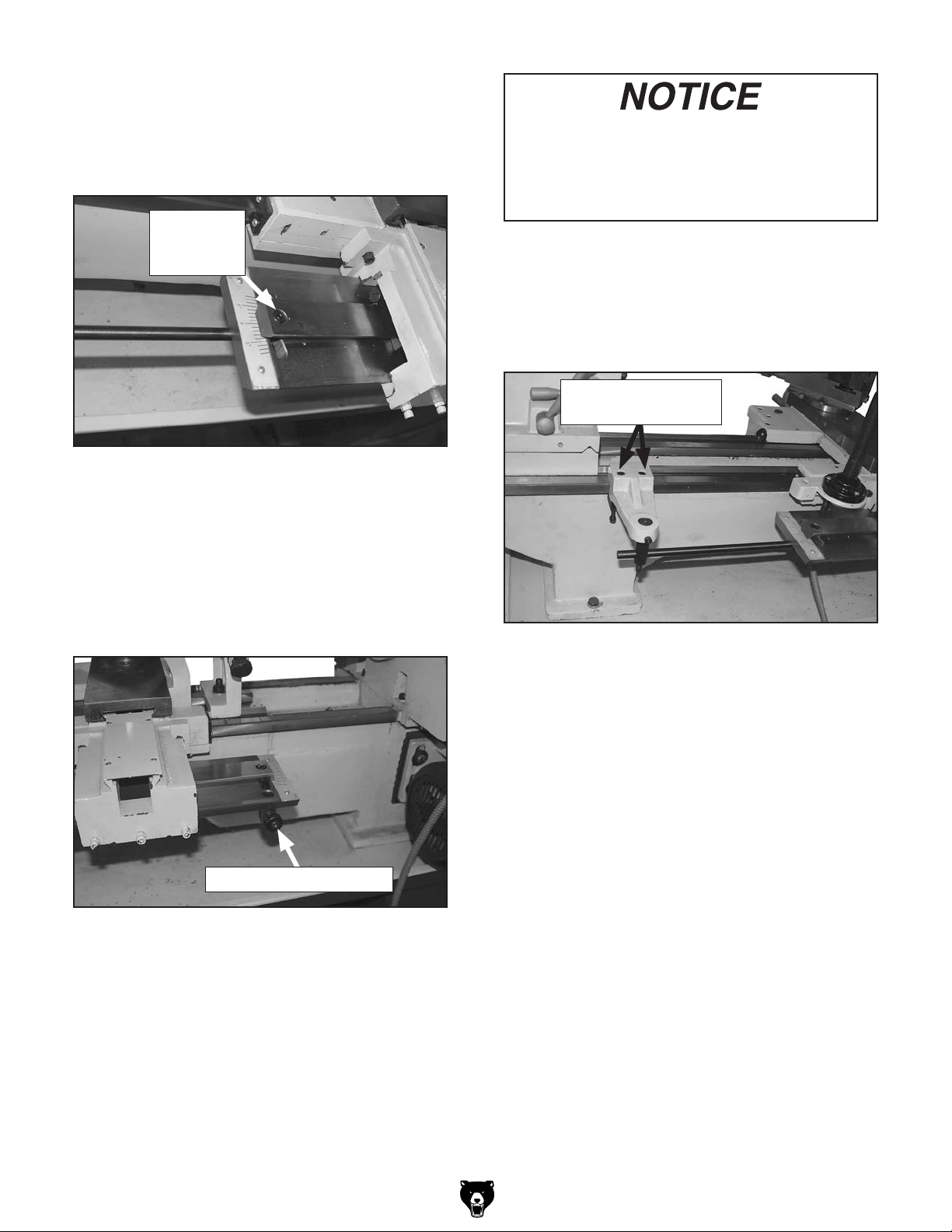
44. Unthread the cable strain relief from the lamp
bracket, then feed the wires through the work
lamp extension shaft.
45. With the wires inserted through the bracket
hole and accessible from the top of the bracket, thread the extension shaft into the second
bracket hole, then reconnect the strain relief
(see Figure 26).
Strain
Relief
Lamp
Bracket
Figure 27. Lamp assembly reattached to saddle.
47. Re-install the compound rest and back splash
on the lathe to complete the taper attachment
assembly procedure.
Original
Extension Shaft Threaded
into Second Hole
Figure 26. Extension shaft threaded into second
hole of lamp bracket.
T10502, T10556, T26300 (Mfg. Since 3/13)
Hole
-9-
Page 10

Determining Amount of Taper
The amount of taper is expressed either in increments per length, such as 1" per foot, or degrees
of angle.
In Figure 28, the increments of taper per length
of the taper is calculated by subtracting the small
workpiece diameter (A) from the large diameter
(B) per the taper length (C).
C
Direction of Taper
The direction of taper is controlled by which way
you rotate the pivot bar.
For instance, if the headstock end of the pivot
bar is rotated toward the bedway, as shown in
Figure 30, the small end of the taper will be at the
tailstock end.
Headstock
B
Workpiece
A
Figure 28. Measuring increments per length of
taper.
For example, if
A = 2"
1
B = 3
⁄2 "
C = 12"
then the amount of taper would be calculated with
the formula B – A per C, as follows:
1
3
⁄2 " - 2" per 12", or 1 1⁄2 " per 12"
In this case, you would set the inches-per-foot
1
scale at ±1
⁄2 .
In Figure 29, the angular amount of taper is deter-
mined by the angular measurement between the
sides of the finished taper.
This End of
Pivot Bar
Rotated In
Small
End
Tailstock
Figure 30. Direction of taper in relation to pivot
bar rotation.
Operation
1. DISCONNECT LATHE FROM POWER!
2. Mount the workpiece between centers.
Angle of
Taper
Workpiece
Figure 29. Taper determined by angular
measurement.
In this case, the angular scale on the tailstock end
of the slide table would be set at the desired angle
of the taper.
-10 -
3. Loosen the bed clamp bracket cap screws
(see Figure 31), position the tooling at
approximately the center of the workpiece,
then retighten the cap screws.
Bed Clamp Bracket
Cap Screws
Figure 31. Location of bracket cap screws.
T10502, T10556, T26300 (Mfg. Since 3/13)
Page 11
4. Make sure each end of the bed clamp rod is
firmly secured.
5. Loosen the cap screw at each end of the
pivot bar (see Figure 32).
Pivot Bar
Cap Screw
(1 of 2)
Figure 32. Pivot bar cap screw
(1 of 2).
6. Determine the amount of taper (refer to the
previous page for more information).
There is always a certain amount of backlash in the taper attachment. To prevent
inconsistent turning results, always start
1
each pass with the tool approximately
⁄2"
behind the starting point on the workpiece.
To disengage the taper attachment:
1. Loosen the bed clamp bracket cap screws
(see Figure 34) so the bed clamp bracket
can freely travel along the bedway.
Bed Clamp Bracket
Cap Screws
7. Use the slide table scales and the taper
adjustment knob (see Figure 33) to adjust
the pivot bar for the desired taper.
Taper Adjustment Knob
Figure 33. Location of taper adjustment knob.
8. Retighten the cap screw on each end of the
pivot bar to secure the setting.
9. Move the carriage by hand to make sure
there is the proper amount of travel to turn
the taper. Make adjustments to the taper
attachment as necessary.
Figure 34. Location of bed clamp bracket cap
screws.
2. Loosen the cap screws at each end of the
pivot bar, rotate the taper adjustment knob
(see Figure 33) to center the bar on the
scales, then retighten the cap screws.
T10502, T10556, T26300 (Mfg. Since 3/13)
-11-
Page 12

Maintenance
To reduce risk of shock or
accidental startup, always
disconnect lathe from
power before adjustments,
maintenance, or service.
Lubricating Slide Table & Dovetail Ways
After cleaning the surfaces of the slide table and
pivot bar (see Figure 35), apply a thin coat of a
quality way oil to these surfaces (see Page 16
for an offering from Grizzly). Slide the attachment
body back and forth along the slide table to distribute the oil along the dovetail ways.
For optimum performance from the taper attachment, follow the maintenance schedule below and
follow specific instructions given in this section.
Daily
• Check/correct loose mounting fasteners.
• Clean debris and grime from all attachment
surfaces.
• Clean/lubricate unpainted surfaces of slide
table and dovetail ways.
• Correct any other unsafe condition.
Monthly
• Disassemble, clean, and lubricate pivot block,
alignment block, and internal ways inside the
attachment body.
Cleaning & Protecting
Typically, the easiest way to clean debris and
grime from the attachment is to use a wet/dry
shop vacuum that is dedicated for this purpose.
The small chips left over after vacuuming can
be wiped up with a slightly oiled rag. Avoid using
compressed air to blow off chips, as it may drive
them deeper into moving surfaces and could
cause sharp chips to fly into your face or hands.
To keep the unpainted surfaces of the slide table
and dovetail ways rust free and in top condition,
apply a thin coat of quality way oil after cleaning
them.
Pivot
Bar
Slide
Table
Figure 35. Slide table and pivot bar.
Lubricating Pivot Block, Alignment Block, &
Internal Ways
1. Remove the top cover from the attachment
body, disconnect the pivot block from the
alignment block, then remove the pivot block
(see Figure 36).
Alignment
Block
Pivot
Block
Internal
Ways
-12-
Figure 36. Internal lubrication points of taper
attachment body.
2. Clean the pivot block, alignment block, and
internal ways of the attachment body with
mineral spirits and shop rags.
3. When dry, apply a thin coat of NLGI#2 grease
to all surfaces of the blocks and internal
ways, then re-assemble the parts.
T10502, T10556, T26300 (Mfg. Since 3/13)
Page 13

Calibrating Scales
There is a small amount of side-to-side adjustment in the slide table angular and inch-per-foot
scales that allow for precise calibration with the
pivot bar (see Figure 37).
Pivot Bar
Indicator Mark
Figure 37. Pivot bar indicator mark and slide
table scale.
Tool Needed Qty
Phillips Screwdriver #2 .......................................1
Scale
Gib Adjustment
The goal of adjusting the gib screws is to remove
sloppiness or “play” from the ways without overadjusting them to the point where they become
stiff and difficult to move.
In general, loose gibs cause poor finishes and
inaccurate tapers; however, over-tightened gibs
cause premature wear and make it difficult to
move the carriage and cross slide.
Tool Needed Qty
Standard Screwdriver #2 ....................................1
Internal Gib
The internal gib is tapered and held in position by
a screw at each end (see Figure 38). To adjust
this gib, turn one screw
1
the other screw
⁄4 turn counterclockwise, so both
screws move in the same direction and the same
amount. Test the feel of the setting by moving the
carriage, and adjust the gib screws as necessary
to make it tighter or looser.
1
⁄4 turn clockwise and
To calibrate the slide table scales:
1. Adjust the pivot bar so that the indicator marks
aligns with the “0” marks on the scales.
2. Turn a length of round stock and measure the
amount of taper, if any, from one end to the
other.
— If there is no taper on the round stock and
the pivot bar indicator marks align with the
“0” mark on each scale, no further adjustment is required.
— If there is no taper on the round stock but
the pivot bar indicator marks do not align
with “0” mark on each scale, continue with
the next step.
— If there is a taper on the round stock, adjust
the pivot bar to remove the taper, then
repeat this step.
3. Loosen the Phillips head screws that secure
the scales, and shift them until the “0” marks
align with the pivot bar indicator mark, then
retighten the screws.
4. To recheck the settings, repeat Step 2.
Internal Gib
Adjustment Screw
(1 of 2)
External
Hex Nuts
Gib
& Cap Screws
Figure 38. Locations of gib components.
Tools Needed Qty
Wrench 10mm ....................................................1
Hex Wrench 5mm ...............................................1
External Gib
The external gib is wedge-shaped and is held in
position by three cap screws (see Figure 38). To
adjust this gib, loosen the hex nuts and turn the
cap screws in equal amounts. Test the feel of the
setting by moving the carriage, and adjust the cap
screws as necessary to make it tighter or looser.
When satisfied with the movement, retighten the
hex nuts to secure the setting.
T10502, T10556, T26300 (Mfg. Since 3/13)
-13-
Page 14

Parts Diagram
13
12
5
15
127
115
117
104
102
125
126
114
106
129
23
18
19
18
17
16
22
6
8
3
3
1
2
14
11
10
9
7
20
21
4
108
139
105
137
128
138
133
134
101
110
132
109
115
136
107
131
119
120
111
113
130
116
122
118
124
123
103
135
121
112
26
121
-14-
T10502, T10556, T26300 (Mfg. Since 3/13)
Page 15

Parts List
REF PART # DESCRIPTION REF PART # DESCRIPTION
1 PT10556001 HANDWHEEL BRACKET (T10556 & T26300) 105 PT10556105 TOP COVER
1 PT10502001 HANDWHEEL BRACKET (T10502) 106 PT10556106 SLIDE BLOCK
2 PCAP06M CAP SCREW M6-1 X 25 107 PT10556107 SLIDE TABLE
3 P51102 THRUST BEARING 51102 108 PT10556108 PIVOT BLOCK
4 PT10556004 GEAR SHAFT 13T (T10556) 109 PT10556109 GIB
4 PT10502004 GEAR SHAFT 19T (T10502) 110 PT10556110 CLAMP BAR
4 PT26300004 GEAR SHAFT 17T (T26300) 111 PT10556111 PIVOT SHAFT
5 PT10556005 CROSS SLIDE LEADSCREW (T10556 & T26300) 112 PT10556112 BED CLAMP PIVOT SHAFT
5 PT10502005 CROSS SLIDE LEADSCREW (T10502) 113 PT10556113 BED CLAMP ROD
6 PT10556006 ALIGNMENT KEY W/ONE HOLE 114 PT10556114 GIB ADJUSTMENT SCREW
7 PT10556007 HANDWHEEL (T10556 & T26300) 115 PCAP13M CAP SCREW M8-1.25 X 30
7 PT10502007 HANDWHEEL (T10502) 116 PT10556116 SHAFT MOUNTING BLOCK
8 PK06M KEY 5 X 5 X 10 117 PCAP11M CAP SCREW M8-1.25 X 16
9 PT10556009 HANDWHEEL RETAINER 118 PT10556118 KNURLED KNOB
10 PT10556010 COMPRESSION SPRING 0.7 X 5 X 10 119 PT10556119 TAPER ADJUSTMENT SHAFT
11 PSTB003M STEEL BALL 6MM 120 PRP02M ROLL PIN 3 X 16
12 PT10556012 HANDWHEEL HANDLE 121 PCAP01M CAP SCREW M6-1 X 16
13 PT10556013 SHOULDER SCREW M8-1.25 X 16 75L 122 PT10556122 BED CLAMP BLOCK
14 PT10556014 GRADUATED DIAL (T10556 & T26300) 123 PCAP45M CAP SCREW M8-1.25 X 45
14 PT10502014 GRADUATED DIAL (T10502) 124 PCAP48M CAP SCREW M6-1 X 35
15 PSS117M SET SCREW M5-.8 X 16 CONE-PT 125 PCAP72M CAP SCREW M10-1.5 X 30
16 PT10556016 THRUST WASHER 126 PRP05M ROLL PIN 5 X 30
17 PT10556017 SPACER 127 PFH27M FLAT HD SCR M4-.7 X 6
18 P51101 THRUST BEARING 51101 128 PCAP109M CAP SCREW M5-.8 X 50
19 PT10556019 ALIGNMENT BLOCK 129 PT10556129 PIVOT BLOCK PIN
20 PN50M HEX NUT M10-1.5 THIN 130 PT10556130 BED CLAMP ROD STOP BLOCK
21 PFH49M FLAT HD SCR M3-.5 X 6 131 PCAP02M CAP SCREW M6-1 X 20
22 PT10556022 CROSS SLIDE LEADSCREW NUT 132 PCAP06M CAP SCREW M6-1 X 25
23 PW06M FLAT WASHER 12MM 133 PN01M HEX NUT M6-1
26 PT10556026 WORK LAMP EXTENSION SHAFT 134 PSS134M SET SCREW M6-1 X 20 CUP-PT
101 PT10556101 BODY 135 PT10556135 TPF SCALE PLATE
102 PT10556102 PIVOT BLOCK 136 PS79M PHLP HD SCR M3-.5 X 8
103 PT10556103 BED CLAMP BRACKET (T10556 & T26300) 137 PT10556137 REAR COVER
103 PT10502103 BED CLAMP BRACKET (T10502) 138 PCAP03M CAP SCREW M5-.8 X 8
104 PT10556104 ALTERNATE LEADSCREW REAR BRACKET 139 PT10556139 ANGLE SCALE PLATE
T10502, T10556, T26300 (Mfg. Since 3/13)
-15-
Page 16
Accessories
order online at www.grizzly.com or call 1-800-523-4777
NOTICE
Refer to our website or latest catalog for
additional recommended accessories.
T23962—ISO 68 Moly-D Way Oil, 5 gal.
T23963—ISO 32 Moly-D Machine Oil, 5 gal.
Moly-D oils are some of the best we've found for
maintaining the critical components of machinery
because they tend to resist run-off and maintain
their lubricity under a variety of conditions—as
well as reduce chatter or slip. Buy in bulk and
save with 5-gallon quantities.
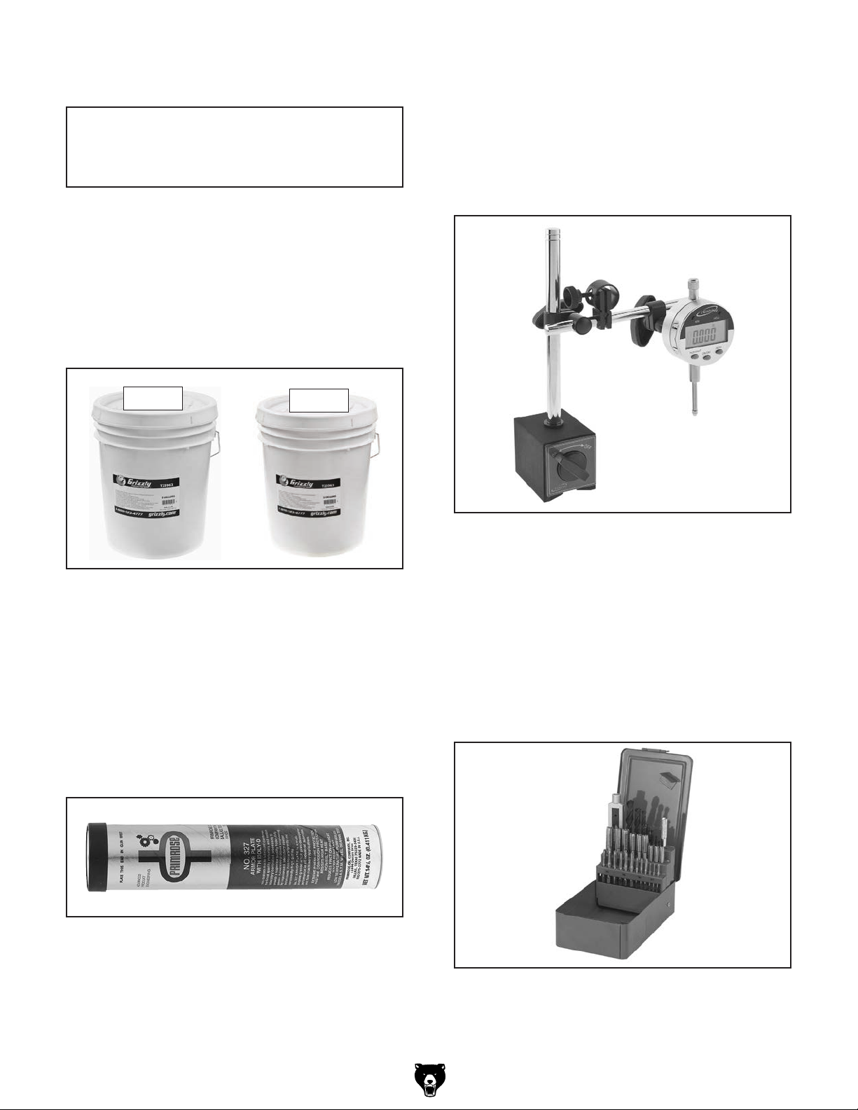
T24802—iGaging® Digital Indicator & Magnetic
Base Set
Includes iGaging
which has a range of 0–6"/150mm, and can read
and convert in inch, metric, and fractions. Fine
adjustment magnetic base has 85 lbs. of pull
power. Magnetic indicator back for position indicator on metal surfaces. Protective case included.
®
3-reading digital indicator,
T23962
Figure 39. ISO 68 and ISO 32 machine oil.
T23964—Armor Plate with Moly-D MultiPurpose Grease, 14.5 oz. (NLGI#2 Equivalent)
Armor Plate with Moly-D is a rich green moly
grease that provides excellent stability and unsurpassed performance under a wide range of
temperatures and operating conditions. Armor
Plate grease is entirely unique due to the fact that
the moly in it is solubilized which provides superior performance to other greases containing the
black solid form of molybdenum disulfide.
T23963
®
Figure 41. Model T24802 iGaging
Indicator & Magnetic Base Set.
G9766—29 Piece HSS Metric Drill & Tap Set
We offer a set of taps with all the drill bits necessary to produce perfectly tapped holes, Each size
has three tapes which include a starting taper
tap, a secondary intermediate tap, and a finishing
bottom tap. These are great taps for those hardto-tap materials. Sizes: M3-0.5, M4-0.7, M5-0.8,
M6-1.0, M8-1.25, M10-1.5, and M12-1.75. Includes
tap handle and storage case.
Digital
Figure 40. T23964 Armor Plate with Moly-D
Multi-Purpose Grease
Figure 42. Model G9766 Drill & Tap Set.
-16 -
T10502, T10556, T26300 (Mfg. Since 3/13)
 Loading...