

Page 1
MODEL T1251
25" X 72" BEECH
CABINETMAKER'S WORKBENCH
INSTRUCTIONS
For questions or help with this product contact Tech Support at (570) 546-9663 or techsupport@grizzly.com
Introduction
This cabinetmaker's workbench is rock-solid and
built to last a lifetime! The Model T1251 features a
3
⁄4" solid beechwood workbench top with 36 pre-
1
drilled
and re-inforced corners. Four 3
wood aprons border the workbench top, providing
a clamping surface for two included 15" vises.
Also included are 8 hex-head bench dogs and 8
steel bars for shelving and stock storage.
5
⁄8" dog holes, all-steel frame construction,
1
⁄2 " solid beech-
Needed for Assembly
• Additional Person ....................................... 1
• Drill ............................................................. 1
• Drill Bit #2 (or Smaller) ............................... 1
• Phillips Screwdriver #2 ............................... 1
• Adjustable Wrench ..................................... 1
• Pencil .......................................................... 1
• Level or Straightedge 3' ............................. 1
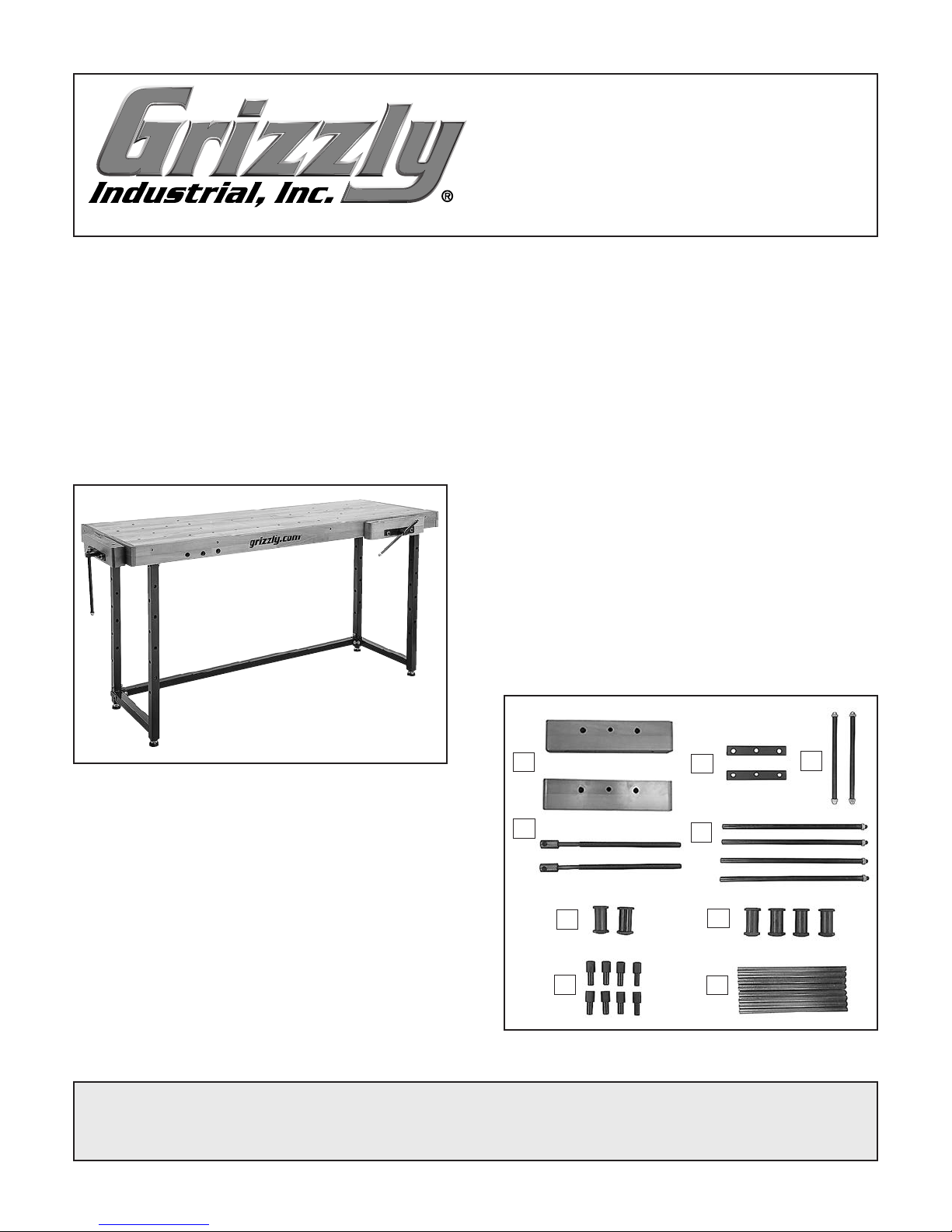
Inventory
Description Qty
A. Vise Heads ................................................. 2
B. Vise Plates.................................................. 2
C. Vise Handles w/Acorn Nuts
D. Vise Screw Rods w/Ends. .......................... 2
E. Vise Bars w/Hex Nuts
F. Threaded Sleeves w/Hex Nuts
7
G. Sleeves w/Hex Nuts
⁄8"-16. ........................ 4
H. Hex-Head Bench Dogs. .............................. 8
5
I. Steel Bars
⁄8" x 113⁄4" ................................. 8
1
⁄2 "-12 ............. 2
1
⁄2 "-12 ...................... 4
7
⁄8"-16 ......... 2
Figure 1. Model T1251 25" x 72" Beech
Cabinetmaker's Workbench.
Specifications
• Workbench Top (Width x Length) ...25" x 72"
• Footprint (Width x Length) ..............20" x 64"
• Height ......................................................37"
• Workbench Vises ....................................... 2
• Vise Mounting Locations ............................ 4
• Dog Holes in Workbench Top .................. 36
• Dog Holes in Vise ........................ 2 Per Side
• Dog Hole Diameter ...................................
• Maximum Weight Capacity ......... 2500+ lbs.
• Approximate Assembly Time ............. 1 Hour
COPYRIGHT © NOVEMBER, 2017 BY GRIZZLY INDUSTRIAL, INC.
NO PORTION OF THIS MANUAL MAY BE REPRODUCED IN ANY SHAPE
OR FORM WITHOUT THE WRITTEN APPROVAL OF GRIZZLY INDUSTRIAL, INC.
(FOR MODELS MFD. SINCE 11/17) #ES19302 PRINTED IN TAIWAN
5
⁄8"
A
D
F
H
B
E
G
I
C
Figure 2. Inventory : vises and accessories.
V1.12.17
Page 2
Description Qty
J. Back Apron ................................................ 1
K. Left Apron ................................................... 1
L. Workbench Top .......................................... 1
M. Right Apron ................................................ 1
N. Front Apron................................................. 1
O. End Frames. ............................................... 2
P. Lower Support ............................................ 1
Q. Upper Back Support ................................... 1
R. Upper Front Support .................................. 1
S. Rubber Feet M10-1.5 x 35 .......................... 4
T. Hardware Bag
— External Corner Braces .......................... 6
—Internal Corner Braces ........................... 6
—Button Hd Cap Screws M8-1.25 x 55 ... 22
— Flat Washers 8mm ................................ 40
— Lock Nuts M8-1.25 ................................ 18
—Tap Screws M4 x 25 ............................. 18
—Open-End Wrench 13/14mm .................. 1
— Hex Wrench 5mm ................................... 1
— Hex Wrench 2.5mm ................................ 1
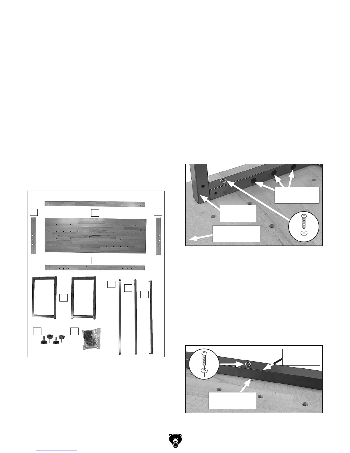
Assembly
1. Lay workbench top upside-down on a
protected surface, such as cardboard or a
blanket.
Note: Bottom-side of workbench top has
threaded holes.
2. Attach each end frame to workbench top with
(2) M8-1.25 x 55 button head cap screws
and (2) 8mm flat washers (see Figure 4).
DO NOT fully tighten fasteners yet.
IMPORTANT: Match backside of end
frames with backside of workbench top
(see Figure 4). Holes for vise mounting are
closer to frontside of end frames.
K
O
S T
Figure 3. Inventory: workbench.
J
L
N
P
Q
R
M
Holes for
Vise Mounting
Backside of
End Frame
Backside of
Workbench Top
Figure 4. End frame attached to workbench top.
3. Attach upper back support and upper front
support to workbench top with (2) M8-1.25 x
55 button head cap screws and (2) 8mm flat
washers (see Figure 5). DO NOT fully tighten
fasteners yet.
IMPORTANT:
backside of workbench top and upper front
support with frontside of workbench top. Upper
front support has holes for vise mounting.
x 2
Match upper back support with
x 2
Upper Back
Support
-2-
Backside of
Workbench Top
Figure 5. Upper back support attached to
workbench top.
Model T1251 (Mfd. Since 11/17)
Page 3

4. Secure end frames and upper supports
with (4) external corner braces and (4) internal
corner braces, using (12) M8-1.25 x 55 button head cap screws, (24) 8mm flat washers,
and (12) M8-1.25 lock nuts (see Figure 6).
DO NOT fully tighten fasteners yet.
x 12
6. Thread rubber feet into bottoms of end
frames (see Figure 8).
Rubber
Foot
External
Corner
Brace
End Frame
Internal
Corner
Brace
Upper Back
Support
Figure 6. End frame and upper back support
secured together with corner braces.
5. Secure end frames and lower support with
(2) external corner braces and (2) internal
corner braces, using (6)M8-1.25 x 55 button
head cap screws, (12) 8mm flat washers, and
(6) M8-1.25 lock nuts (see Figure7). DO NOT
fully tighten fasteners.
End Frame
Figure 8. Rubber foot threaded into bottom of
end frame.
7. Turn workbench upright. Make sure it is
centered over end frames and supports (not
leaning to one side or the other), then fully
tighten all fasteners.
8. Adjust feet as necessary to ensure workbench sits firmly on ground and does not
rock.
Option: Lay a level across workbench from
side-to-side and end-to-end when adjusting
feet.
9. Select two attachment locations to install
vises.
Tip: Consider full-range of vise movement
and workbench position when selecting
attachment locations for vises.
External
Corner
Brace
Lower
Support
End Frame
Figure 7. End frame and lower support secured
together with corner braces.
Model T1251 (Mfd. Since 11/17)
Internal
Corner
Brace
x 6
7
10. Remove (6)
⁄8"-16 hex nuts from (4) sleeves
and (2) threaded sleeves.
-3-
Page 4

11. Insert (4) sleeves and (2) threaded sleeves
through mounting holes in end frames and
7
upper front support and secure with (6)
⁄8"-16
hex nuts (see Figure 9).
IMPORTANT: Threaded sleeves must be
inserted through center mounting holes. To
ease future relocation of vises, insert all
sleeves so hex nuts face outward.
Threaded
Sleeve
Sleeve
Sleeve
Side of
Workbench Top
x 12
Pilot Hole
Countersunk
Hole
Front Apron
7
⁄8"-16 Hex Nut
(Facing Outward)
Upper Front
Support
Figure 9. Sleeves inserted through upper front
support.
12. Position front and rear aprons alongside workbench top and mark holes on
side of workbench top using countersunk
holes in aprons as templates, as shown in
Figure 10.
Tip: Use a level or straightedge to align top
of aprons with workbench top.
Workbench Top
Level
Figure 11. Attaching front apron.
14. Position left and right aprons alongside work-
bench top. Mark holes on side of workbench
top using countersunk holes in aprons as
templates.
Tip: Use a level or straightedge to align top
of aprons with workbench top.
15. Drill pilot holes at marks made in Step 14,
and secure front and rear aprons with (6) M4
x 25 tap screws.
IMPORTANT: Make sure vise mounting
holes in end frames and left and right aprons
are aligned.
16. Remove ends from (2) vise screw rods by
loosening (2) M5-.8 x 12 set screws, as
shown in Figure 12.
Top of
Front Apron
Figure 10. Positioning apron and marking holes.
13. Drill pilot holes at marks made in Step 12,
and secure front and rear aprons with (12)
M4 x 25 tap screws, as shown in Figure 11.
IMPORTANT: Make sure vise mounting
holes in upper front support and front apron
align.
-4-
Countersunk
Hole
Vise Screw
x 2
Rod End
Vise
Screw Rod
Figure 12. Removing end from vise screw rod
(1 of 2).
Model T1251 (Mfd. Since 11/17)
Page 5

17. Insert (2) vise screw rods through (2) vise
heads and (2) vise plates. Secure with
(2) vise screw rod ends (see Figure 13).
Vise
x 2
Screw Rod
Vise
Head
Vise Screw
Rod End
Vise
Plate
Figure 13. Vise screw rod attached to vise head
(1 of 2).
18. Attach (4) vise bars to (2) vise heads with
1
⁄2 "-12 hex nuts (see Figure 14). Insert
(4)
(2) vise handles through (2) vise screw rod
1
ends and secure with (4)
⁄2 "-12 acorn nuts
(see Figure 14).
Front Apron
Vise
Assembly
Figure 15. Vise assembly attached to workbench
(1 of 2).
20. Insert steel bars through end frames as
desired (see Figure 16).
Note: Legs of end support frames have
several holes, allowing for numerous
shelving and stock storage configurations.
Vise Plate
Vise
Bar
Vise
x 4
Head
Vise Screw Rod End
Vise Handle
x 4
Figure 14. Vise bars and vise handle attached to
vise head (1 of 2).
19. Insert vise assemblies through aprons and
into vise sleeves, then slowly turn vise handles clockwise to thread vise screw rods into
threaded sleeves (see Figure 15).
Steel
Bars
End Frame
Figure 16. Steel bars inserted into end support
frames.
21. Insert hex-head bench dogs into dog holes in
workbench top as desired (see Figure 17).
Dog
Holes
Hex-Head
Bench Dogs
Workbench
Top
Figure 17. Workbench dogs inserted into dog
holes.
Model T1251 (Mfd. Since 11/17)
-5-
Page 6

T1251 Parts Breakdown
24
22
20
21
29
18
30
23
31
17
32
26
16
33
19
28
14
13
17
6
7
8
4
9
8
10
9
8
9
6
10
10
7
9
9
6
12
8
9
6
8
9
10
9
9
10
9
3
9
10
7
9
2
10
9
8
5
1
9
15
13
29
12
2
11
25
8
14
4
3
15
17
18
20
22
17
2
29
27
11
5
16
19
24
23
21
2
REF PART # DESCRIPTION REF PART # DESCRIPTION
1 PT1251001 WORKBENCH TOP 25 X 72 X 1-3/4 18 PT1251018 VISE HEAD
2 PT1251002 END FRAME 19 PT1251019 VISE PLATE
3 PT1251003 UPPER FRONT SUPPORT 20 PT1251020 HEX NUT 1/2-12
4 PT1251004 UPPER BACK SUPPORT 21 PT1251021 VISE ROD END
5 PT1251005 LOWER SUPPORT 22 PT1251022 SET SCREW M5-.8 X 12
6 PT1251006 EXTERNAL CORNER BRACE 23 PT1251023 VISE HANDLE 1/2-12 X 11-3/4
7 PT1251007 INTERNAL CORNER BRACE 24 PT1251024 ACORN NUT 1/2-12
8 PT1251008 BUTTON HD CAP SCR M8-1.25 X 55 25 PT1251025 RIGHT APRON
9 PT1251009 FLAT WASHER 8MM 26 PT1251026 LEFT APRON
10 PT1251010 LOCK NUT M8-1.25 27 PT1251027 FRONT APRON
11 PT1251011 RUBBER FOOT M10-1.5 X 35 28 PT1251028 REAR APRON
12 PT1251012 STEEL BAR 5/8 X 11-3/4 29 PT1251029 TAP SCREW M4 X 25
13 PT1251013 THREADED SLEEVE 1 X 2, 7/8-16, 5/8-11 30 PT1251030 HEX WRENCH 2.5MM
14 PT1251014 SLEEVE 1 X 2, 7/8-16 31 PT1251031 HEX WRENCH 5MM
15 PT1251015 HEX NUT 7/8-16 32 PT1251032 WRENCH 13/14MM OPEN-ENDS
16 PT1251016 VISE SCREW ROD 5/8-11 X 15-1/2 33 PT1251033 HEX-HEAD BENCH DOG 5/8 X 2-1/2
17 PT1251017 VISE BAR 1/2-12 X 18-1/2
-6-
BUY PARTS ONLINE AT GRIZZLY.COM!
Scan QR code to visit our Parts Store.
Model T1251 (Mfd. Since 11/17)
 Loading...