

Grizzly T1243 Owner's Manual
MODEL T1243
CROSS-SLIDE
ROTARY TABLE 7" X 9"
OWNER'S MANUAL
(For models manufactured since 02/18)
COPYRIGHT © MAY, 2018 BY GRIZZLY INDUSTRIAL, INC.
WARNING : NO PORTION OF THIS MANUAL MAY BE REPRODUCED IN ANY SHAPE
OR FORM WITHOUT THE WRITTEN APPROVAL OF GRIZZLY INDUSTRIAL, INC.
#KB19355 PRINTED IN CHINA
V1. 0 5.18

This manual provides critical safety instructions on the proper setup,
operation, maintenance, and service of this machine/tool. Save this
document, refer to it often, and use it to instruct other operators.
Failure to read, understand and follow the instructions in this manual
may result in fire or serious personal injury—including amputation,
electrocution, or death.
The owner of this machine/tool is solely responsible for its safe use.
This responsibility includes but is not limited to proper installation in
a safe environment, personnel training and usage authorization,
proper inspection and maintenance, manual availability and comprehension, application of safety devices, cutting/sanding/grinding tool
integrity, and the usage of personal protective equipment.
The manufacturer will not be held liable for injury or property damage
from negligence, improper training, machine modifications or misuse.
Some dust created by power sanding, sawing, grinding, drilling, and
other construction activities contains chemicals known to the State
of California to cause cancer, birth defects or other reproductive
harm. Some examples of these chemicals are:
• Lead from lead-based paints.
• Crystalline silica from bricks, cement and other masonry products.
• Arsenic and chromium from chemically-treated lumber.
Your risk from these exposures varies, depending on how often you
do this type of work. To reduce your exposure to these chemicals:
Work in a well ventilated area, and work with approved safety equipment, such as those dust masks that are specially designed to filter
out microscopic particles.

Table of Contents
INTRODUCTION ............................................................................................................................... 2
Manual Accuracy ........................................................................................................................ 2
Machine Data Sheet ................................................................................................................... 2
Contact Info ................................................................................................................................ 2
Machine Description ................................................................................................................... 3
Identification ............................................................................................................................... 3
Controls & Components ............................................................................................................. 4
SECTION 1: SAFETY ....................................................................................................................... 5
Safety Instructions for Machinery ............................................................................................... 5
SECTION 2: SETUP ......................................................................................................................... 6
Unpacking .................................................................................................................................. 6
Needed for Setup ....................................................................................................................... 6
Inventory ..................................................................................................................................... 6
Assembly .................................................................................................................................... 7
SECTION 3: OPERATIONS ............................................................................................................. 8
Operation Overview.................................................................................................................... 8
Rotary Table Movement ............................................................................................................. 8
Adjusting Handwheel Scale ....................................................................................................... 9
Adjusting Indexing Scale ............................................................................................................ 9
Mounting Table Horizontally ....................................................................................................... 9
Mounting Table Vertically ......................................................................................................... 11
Aligning Workpiece with Mill Spindle ....................................................................................... 12
Aligning Table with Mill Machine X-Axis .................................................................................. 12
Angular Indexing ...................................................................................................................... 13
SECTION 4: ACCESSORIES ......................................................................................................... 14
SECTION 5: MAINTENANCE......................................................................................................... 17
Schedule .................................................................................................................................. 17
Cleaning & Protecting .............................................................................................................. 17
Lubrication ................................................................................................................................ 17
Adjusting Gibs .......................................................................................................................... 19
SECTION 6: PARTS ....................................................................................................................... 20
T1243 Parts .............................................................................................................................. 20
WARRANTY & RETURNS ............................................................................................................. 25

INTRODUCTION
We are proud to offer this document with your
new machine! We've made every effort to be
exact with the instructions, specifications, drawings, and photographs of the machine we used
when writing this manual. However, sometimes
we still make an occasional mistake.
Also, owing to our policy of continuous improvement, your machine may not exactly match
the manual
the difference between the manual and machine
leaves you in doubt, immediately call our technical support for updates or clarification.
For your convenience, we post all available documentation on our website at
.
Any updates to this document will be reflected on
our website as soon as complete.
We stand behind our machines! If you have questions or need help, contact us with the information
below. Before contacting, make sure you get the
serial number
from the
machine ID label. This will help us help you faster.
We want your feedback on this manual. What did
you like about it? Where could it be improved?
Please take a few minutes to give us feedback.
Manual Accuracy
. If you find this to be the case, and
www.grizzly.com
Contact Info
and manufacture date
Grizzly Technical Support
1815 W. Battlefield
Springfield, MO 65807
Phone: (570) 546-9663
Email: techsupport@grizzly.com
Grizzly Documentation Manager
P.O. Box 2069
Bellingham, WA 98227-2069
Email: manuals@grizzly.com
Customer Service #: (570) 546-9663 · To Order Call: (800) 523-4777 · Fax #: (800) 438-5901
MODEL T1243 CROSS-SLIDE ROTARY TABLE 7 X 9"
Worm Gear Ratio...................................................................................................................................... 90:1
Table Rotation ......................................................................................................................................... 360°
Rotary Table Rotation Per Handwheel Revolution .......................................................................................4°
Handwheel Scale Resolution (Smallest Indicated Adjustment)............................................................. 0.001"
Table Size ............................................................................................................................................. 7" x 9"
Table T-Slots ..............................................................................................................................................
Table Height ............................................................................................................................................. 7
X-Axis Table Travel ....................................................................................................................................4
Y-Axis Table Travel ....................................................................................................................................4
Base Footprint (Horizontal/Vertical).............................. 8" L x 7
Overall Width (Side-to-Side) .......................................................................................................................15"
Overall Depth (Front-to-Back) .................................................................................................................12
Full Range of Movement Width .................................................................................................................. 15"
Full Range of Movement Depth ..................................................................................................................20"
Weight .................................................................................................................................................. 60 lbs.
-2-
7
1
⁄2 " W (Horizontal), 71⁄2 " L x 71⁄2 " W (Vertical)
Model T1243 (Mfd. Since 02/18)
⁄16"
1
⁄2 "
1
3
3
⁄4"
⁄4"
⁄4"
To reduce your risk of
serious injury, read this
entire manual BEFORE
Machine Description
The T1243 Cross-Slide Rotary Table allows users
to perform milling operations up to 360° around a
fixed axis, as well as move up to 4" along both the
X and Y axes. Three handwheels control rotation
and table movement.
The T1243 can be mounted horizontally or vertically on a mill-drill table. The supplied T-bolts and
hold-down clamps are designed to work with milling machine tables that have
7
⁄16" or 1⁄2 " T-slots.
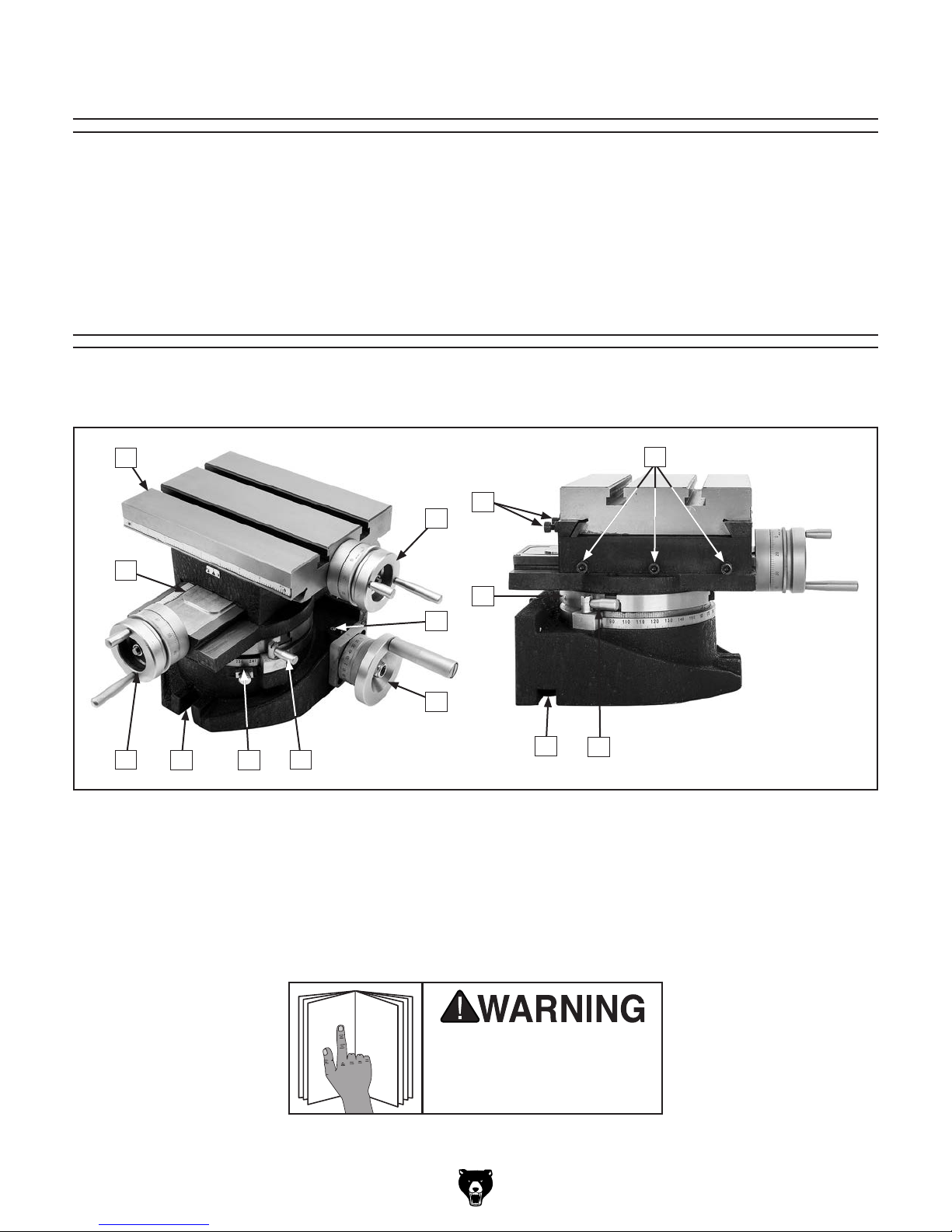
Identification
Become familiar with the names and locations of the controls and features shown below to better understand
the instructions in this manual.
A
J
B
I
L
C
K
D
H
A. Table
B. X-Axis Handwheel w/Graduated Scale
C. Ball Oiler for Rotary Table Leadscrew
D. Rotary Table Handwheel w/Graduated Scale
E. Rotary Table Locks
F. Rotary Table Degree Scale and Adjustable
Indicator
FG
E
using machine.
M
G. Horizontal Mounting Slot
H. Y-Axis Handwheel w/Graduated Scale
I. Y-Axis Leadscrew Cover
J. X-Axis Gib Adjustment Screws (2 of 3)
K. Y-Axis Gib Adjustment Screws
L. Ball Oiler for Rotary Table Worm Gear
M. Vertical Mounting Slot (1 of 2)
E
Model T1243 (Mfd. Since 02/18)
-3-
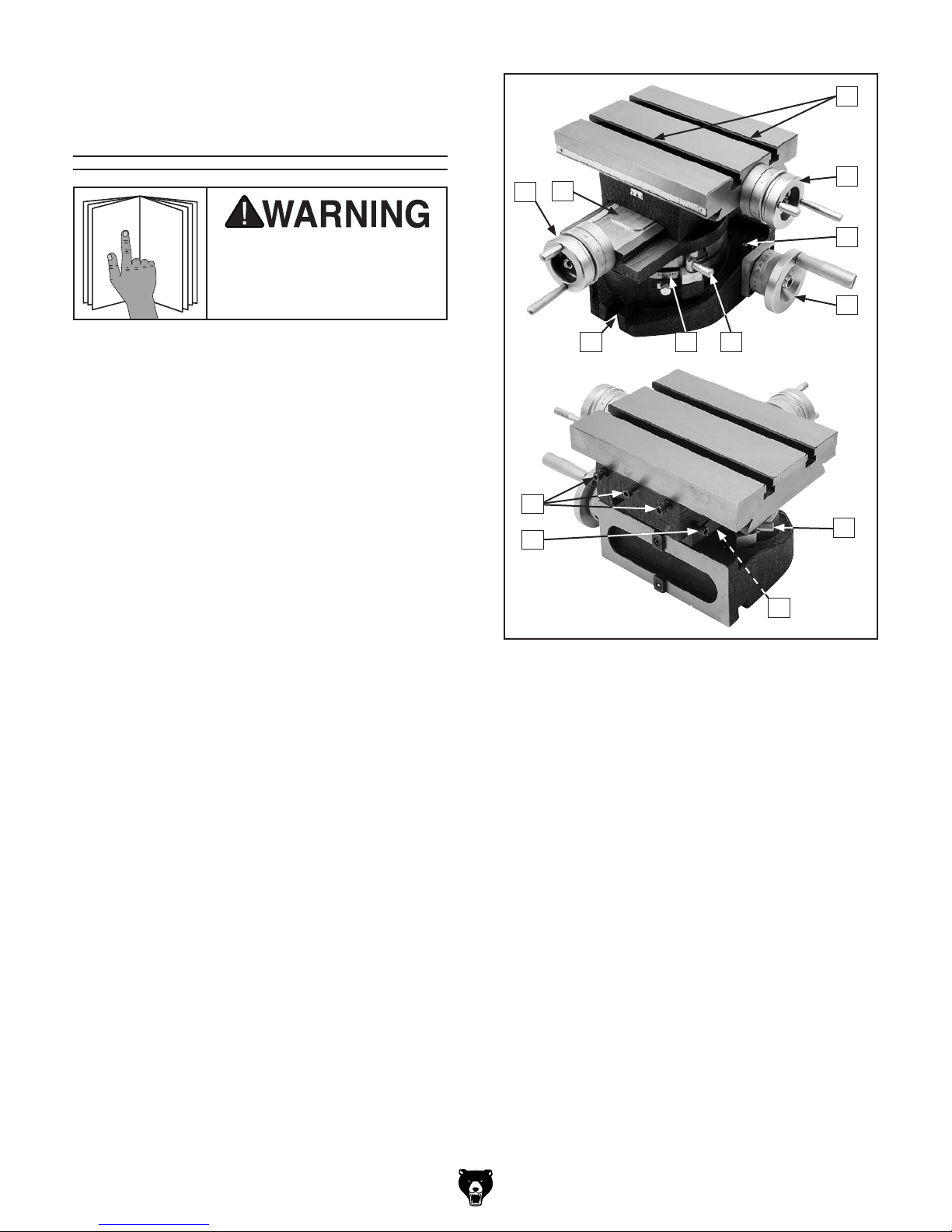
Controls &
To reduce your risk of
serious injury, read this
entire manual BEFORE
Components
C
using machine.
Refer to the following figures and descriptions to
become familiar with the basic controls and components of this machine. Understanding these
items and how they work will help you understand
the rest of the manual and minimize your risk of
injury when operating this machine.
A. Y-Axis Handwheel w/Graduated Scale:
Moves table forward and backward when
handwheel is perpendicular to rotary table
handwheel (F) as shown; moves table side
to side on X-axis when handwheel is parallel
with rotary table handwheel. One full turn of
the handwheel moves the table 0.1".
B
A
HI
G
J
K
E
D
E
F
G
B. Y-Axis Leadscrew Cover: Protects
leadscrew from debris and provides access
for lubrication.
C. Table T-Slots: Are used to secure a workpiece
to the table with
D. X-Axis Handwheel w/Graduated Scale:
Moves table side to side when handwheel
is parallel with rotary table handwheel (F) as
shown; moves table forward and backward
on Y-axis when handwheel is perpendicular
to rotary table handwheel. One full turn of the
handwheel moves the table 0.1".
E. Ball Oilers: Are used to lubricate the rotary
table leadscrew and worm gear.
F. Rotary Table Handwheel w/Graduated
Scale: Rotates the table through a full 360°
rotation. One full rotation of the handwheel
turns the table 4°.
7
⁄16" or 10mm fasteners.
Figure 1. T1243 controls and components.
G. Rotary Table Locks: Lock the table in place.
This reduces the stress on the worm and
spur gear interface and helps ensure the
table does not change position during heavy
machining operations.
H. Rotary Table Degree Scale: Graduated in
whole degrees for rotational table positioning.
I. Horizontal Mounting Slot: Use to attach
T1243 to milling machine table with T-bolt.
J. Table Gib Adjustment Screws: Provide
adjustment for play in the table without causing the slides to bind.
K. Cross Slide Gib Adjustment Screw (1 of
3): Provides adjustment for play in the cross
slide without causing the slides to bind.
-4-
Model T1243 (Mfd. Since 02/18)
SECTION 1: SAFETY
For Your Own Safety, Read Instruction
Manual Before Operating This Machine
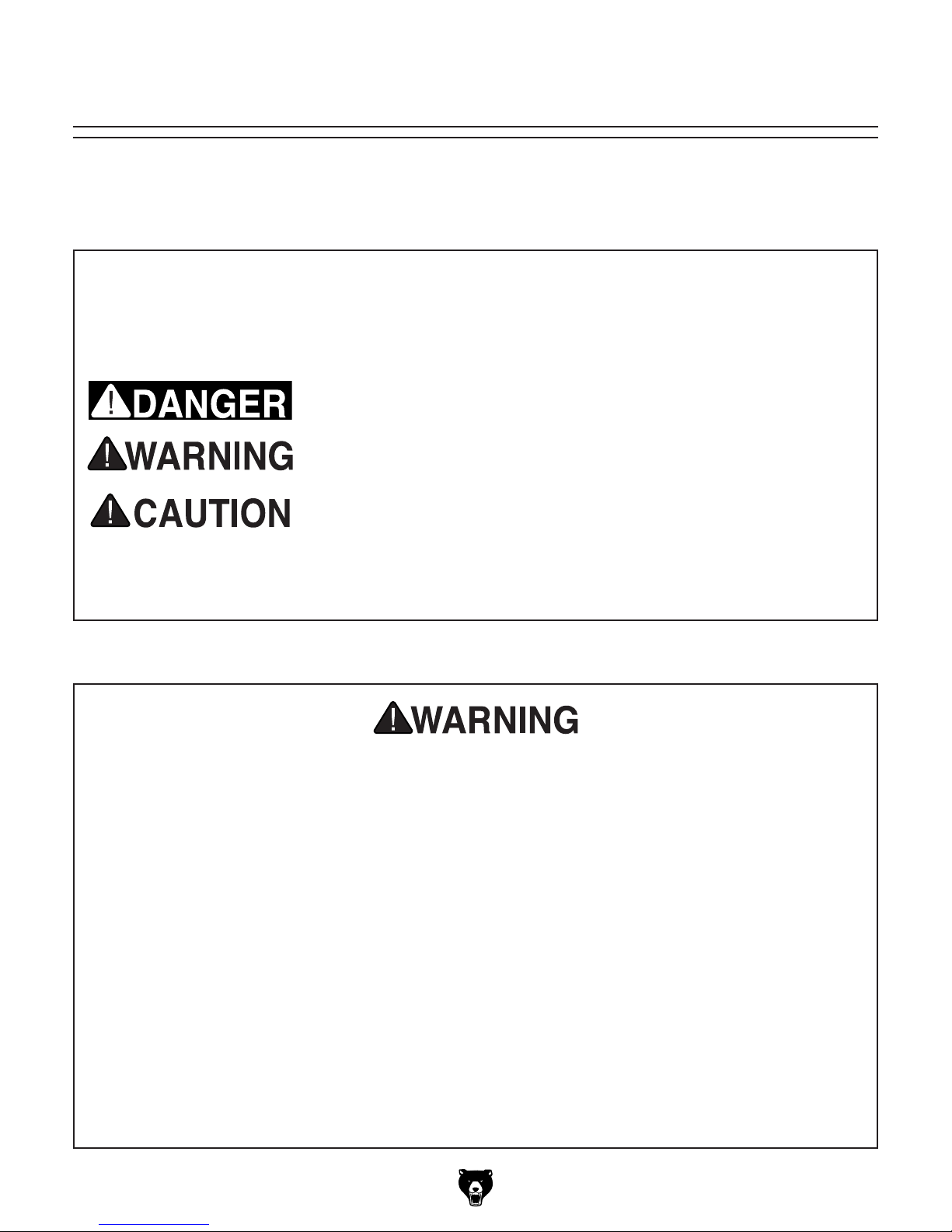
The purpose of safety symbols is to attract your attention to possible hazardous conditions.
This manual uses a series of symbols and signal words intended to convey the level of importance of the safety messages. The progression of symbols is described below. Remember that
safety messages by themselves do not eliminate danger and are not a substitute for proper
accident prevention measures. Always use common sense and good judgment.
Indicates an imminently hazardous situation which, if not avoided,
WILL result in death or serious injury.
Indicates a potentially hazardous situation which, if not avoided,
COULD result in death or serious injury.
Indicates a potentially hazardous situation which, if not avoided,
MAY result in minor or moderate injury. It may also be used to alert
against unsafe practices.
This symbol is used to alert the user to useful information about
NOTICE
proper operation of the machine.
Safety Instructions for Machinery
OWNER’S MANUAL. Read and understand this
owner’s manual BEFORE using machine.
TRAINED OPERATORS ONLY. Untrained operators have a higher risk of being hurt or killed.
Only allow trained/supervised people to use this
machine. When machine is not being used, disconnect power, remove switch keys, or lock-out
machine to prevent unauthorized use—especially
around children. Make your workshop kid proof!
DANGEROUS ENVIRONMENTS. Do not use
machinery in areas that are wet, cluttered, or have
poor lighting. Operating machinery in these areas
greatly increases the risk of accidents and injury.
MENTAL ALERTNESS REQUIRED. Full mental
alertness is required for safe operation of machinery. Never operate under the influence of drugs or
alcohol, when tired, or when distracted.
ELECTRICAL EQUIPMENT INJURY RISKS. You
can be shocked, burned, or killed by touching live
electrical components or improperly grounded
machinery. To reduce this risk, only allow qualified
service personnel to do electrical installation or
repair work, and always disconnect power before
accessing or exposing electrical equipment.
DISCONNECT POWER FIRST.
nect machine from power supply BEFORE making
adjustments, changing tooling, or servicing machine.
This prevents an injury risk from unintended startup
or contact with live electrical components.
EYE PROTECTION. Always wear ANSI-approved
safety glasses or a face shield when operating or
observing machinery to reduce the risk of eye
injury or blindness from flying particles. Everyday
eyeglasses are NOT approved safety glasses.
Always discon-
Model T1243 (Mfd. Since 02/18)
-5-
SECTION 2: SETUP
This machine was carefully packaged for safe
transport. When unpacking, separate all enclosed
items from packaging materials and inspect them
for shipping damage.
,
please
IMPORTANT:
you are completely satisfied with the machine and
have resolved any issues between Grizzly or the
shipping agent. You MUST have the original pack-
aging to file a freight claim. It is also extremely
helpful if you need to return your machine later.
Keep children and pets away
from plastic bags or packing
materials shipped with this
The following is a list of items shipped with your
machine. Before beginning setup, lay these items
out and inventory them.
If any non-proprietary parts are missing (e.g. a
nut or a washer), we will gladly replace them; or
for the sake of expediency, replacements can be
obtained at your local hardware store.
Unpacking
If items are damaged
call us immediately at (570) 546-9663.
Save all packaging materials until
SUFFOCATION HAZARD!
machine. Discard immediately.
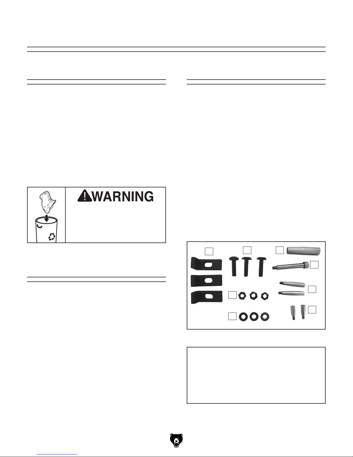
Inventory
Box 1 (Figure 2) Qty
A. Cross-Slide Rotary Table (Not Shown) ...... 1
B. Hold-Down Clamps .................................... 3
C. T-B o lts ........................................................ 3
D. Handwheel Handle ..................................... 1
E. Shoulder Screw .......................................... 1
F. Fixed Handles 58mm ................................. 2
G. Fixed Handles 38mm ................................. 2
H. Flat Washers 10mm ................................... 3
I. Hex Nuts M10-1.5 ....................................... 3
Needed for Setup
The following items are needed, but not included,
for the setup/assembly of this machine.
Description Qty
• Safety Glasses ........................................... 1
• Screwdriver Flat Head #2 ........................... 1
-6-
B
Figure 2. T1243 inventory.
C D
E
F
I
G
H
NOTICE
If you cannot find an item on this list, carefully check around/inside the machine and
packaging materials. Often, these items get
lost in packaging materials while unpacking or they are pre-installed at the factory.
Model T1243 (Mfd. Since 02/18)
Assembly
The machine must be fully assembled before it
can be operated. Before beginning the assembly
process, refer to
and gather
all
To ensure the assembly process
goes smoothly, first clean any
covered or coated in heavy-duty rust preventative (if
applicable).
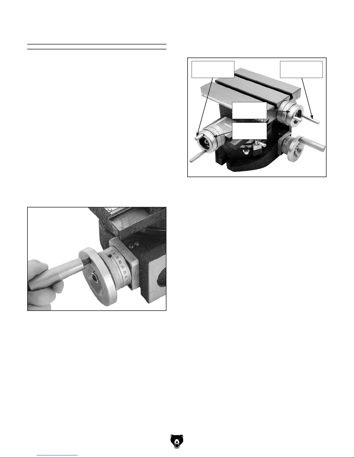
2. Thread (1) fixed handle 38mm and (1)
fixed handle 58mm into X-axis and Y-axis
handwheels (see Figure 4). Hand tighten.
Needed for Setup
listed items.
parts that are
The T1243 Cross-Slide Rotary Table comes fully
assembled except for the handwheel handles.
Items Needed Qty
Flat Head Screwdriver #2 .................................. 1
To assemble machine:
1. Insert shoulder screw into handwheel handle,
then attach shoulder screw to 3" rotary table
handwheel as shown in Figure 3.
Fixed
Handle 38mm
X-Axis
Handwheel
Y-Axis
Handwheel
Figure 4. Fixed handles installed on X- and
Y-axis handwheels.
Fixed
Handle 58mm
Figure 3. Installing shoulder screw and handle
without shaft into rotary table handwheel.
Model T1243 (Mfd. Since 02/18)
-7-
 Loading...