

Page 1

MODEL T1188
EDGEBANDING TRIM ROUTER
OWNER'S MANUAL
(For models manufactured since 06/17)
WARNING: NO PORTION OF THIS MANUAL MAY BE REPRODUCED IN ANY SHAPE
COPYRIGHT © SEPTEMBER, 2017 BY GRIZZLY INDUSTRIAL, INC.
OR FORM WITHOUT THE WRITTEN APPROVAL OF GRIZZLY INDUSTRIAL, INC.
#JH18877 PRINTED IN TAIWAN
V1.09.17
Page 2

This manual provides critical safety instructions on the proper setup,
operation, maintenance, and service of this machine/tool. Save this
document, refer to it often, and use it to instruct other operators.
Failure to read, understand and follow the instructions in this manual
may result in fire or serious personal injury—including amputation,
electrocution, or death.
The owner of this machine/tool is solely responsible for its safe use.
This responsibility includes but is not limited to proper installation in
a safe environment, personnel training and usage authorization,
proper inspection and maintenance, manual availability and comprehension, application of safety devices, cutting/sanding/grinding tool
integrity, and the usage of personal protective equipment.
The manufacturer will not be held liable for injury or property damage
from negligence, improper training, machine modifications or misuse.
Some dust created by power sanding, sawing, grinding, drilling, and
other construction activities contains chemicals known to the State
of California to cause cancer, birth defects or other reproductive
harm. Some examples of these chemicals are:
• Lead from lead-based paints.
• Crystalline silica from bricks, cement and other masonry products.
• Arsenic and chromium from chemically-treated lumber.
Your risk from these exposures varies, depending on how often you
do this type of work. To reduce your exposure to these chemicals:
Work in a well ventilated area, and work with approved safety equipment, such as those dust masks that are specially designed to filter
out microscopic particles.
Page 3
SECTION 1: SAFETY
Always wear ANSI-
when operating or observing machinery to
For Your Own Safety Read Instruction Manual
Before Operating This Equipment
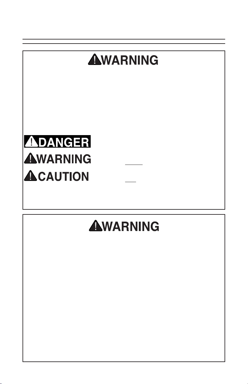
The purpose of safety symbols is to attract your attention to possible hazardous conditions. This manual uses a series of symbols and signal words which
are intended to convey the level of importance of the safety messages. The
progression of symbols is described below. Remember that safety messages by
themselves do not eliminate danger and are not a substitute for proper accident
prevention measures.
Indicates an imminent hazardous situation which, if
not avoided, WILL result in death or serious injury.
Indicates a potentially hazardous situation which, if
not avoided, COULD result in death or serious injury.
Indicates a potentially hazardous situation which, if
not avoided, MAY result in minor or moderate injury.
It may also be used to alert against unsafe practices.
NOTICE
This symbol is used to alert the user to useful information about proper operation of the equipment.
Safety Instructions for Power Tools
OWNER’S MANUAL. Read and under-
stand this owner’s manual BEFORE using
machine.
TRAINED OPERATORS ONLY. Untrained
operators have a higher risk of being hurt
or killed. Only allow trained/supervised
people to use this power tool. When tool
is not being used, disconnect power, and
store in out-of-reach location to prevent
unauthorized use—especially around
children. Make workshop kid proof!
DANGEROUS ENVIRONMENTS. Do not
use tools in areas that are wet, cluttered,
or have poor lighting. Operating tools in
these areas greatly increases risk of accidents and injury.
Model T1188 Edgebanding Trim Router -1-
MENTAL ALERTNESS REQUIRED. Full
mental alertness is required for safe operation of power tools. Never operate under
the influence of drugs or alcohol, when
tired, or when distracted.
DISCONNECT POWER FIRST. Always
disconnect tool from power supply
BEFORE making adjustments, changing tooling, or servicing machine. This
prevents an injury risk from unintended
startup or contact with live electrical components.
EYE PROTECTION.
approved safety glasses or a face shield
reduce the risk of eye injury or blindness
from flying particles. Everyday eyeglasses
are not approved safety glasses.
Page 4

ELECTRICAL SAFETY. Tool plug must
Guards and cov-
in good work-
If at
match outlet. Double-insulated tools have
a polarized plug (one blade is wider than
the other), which must be plugged into a
polarized outlet. Never modify plug. Do
not use adapter for grounded tools. Use
a ground fault circuit interrupter if operation is unavoidable in damp locations.
Avoid touching grounded surfaces when
operating tool.
WEARING PROPER APPAREL. Do not
wear clothing, apparel or jewelry that
can become entangled in moving parts.
Always tie back or cover long hair. Wear
non-slip footwear to avoid accidental
slips, which could cause loss of workpiece
control. Wear hard hat as needed.
HAZARDOUS DUST. Dust created while
using tools may cause cancer, birth
defects, or long-term respiratory damage.
Be aware of dust hazards associated with
each workpiece material, always wear
a NIOSH-approved respirator, and connect tool to an appropriate dust collection
device to reduce your risk.
HEARING PROTECTION. Always wear
hearing protection when operating or
observing loud machinery. Extended
exposure to this noise without hearing
protection can cause permanent hearing
loss.
REMOVE ADJUSTING TOOLS. Never
leave adjustment tools, chuck keys,
wrenches, etc. in or on tool—especially
near moving parts. Verify removal before
starting!
INTENDED USAGE. Only use tool for its
intended purpose. Never modify or alter
tool for a purpose not intended by the
manufacturer or serious injury or death
may result!
AWKWARD POSITIONS. Keep proper
footing and balance at all times when
operating tool. Do not overreach! Avoid
awkward hand positions that make tool
control difficult or increase the risk of
accidental injury.
SAFE HANDLING. Firmly grip tool. To
avoid accidental firing, do not keep finger
on switch or trigger while carrying.
FORCING TOOLS.. Use right tool for job,
and do not force it. It will do job safer and
better at rate for which it was designed.
SECURING WORKPIECE. When
required, use clamps or vises to secure
workpiece. This protects hands and frees
both of them to operate tool.
GUARDS & COVERS.
ers reduce accidental contact with moving parts or flying debris. Ensure they
are properly installed, undamaged, and
working correctly.
CHILDREN & BYSTANDERS. Keep children and bystanders at a safe distance
from the work area. Stop using tool if they
become a distraction.
USE RECOMMENDED ACCESSORIES.
Consult this manual or manufacturer
for recommended accessories. Using
improper accessories will increase risk of
serious injury.
MAINTAIN WITH CARE. Keep cutting
tool edges sharp and clean. Follow all
maintenance instructions and lubrication
schedules to keep tool
ing condition. A tool that is improperly
maintained could malfunction, leading to
serious personal injur y or death. Only
have tool serviced by qualified servicepersonnel using matching replacement
parts.
CHECK DAMAGED PARTS. Regularly
inspect tool for any condition that may
affect safe operation. Immediately repair
or replace damaged or mis-adjusted parts
before operating tool.
MAINTAIN POWER CORDS. When disconnecting cord-connected tools from
power, grab and pull the plug—NOT the
cord. Carrying or pulling the cord may
damage wires inside. Do not handle cord/
plug with wet hands. Avoid cord damage
by keeping it away from heated surfaces,
high traffic areas, harsh chemicals, sharp
edges, moving parts, and wet/damp locations. Damaged cords increase risk of
electrocution.
UNATTENDED OPERATION. Never
leave tool running while unattended. Turn
tool OFF and ensure all moving parts
completely stop before walking away.
EXPERIENCING DIFFICULTIES.
any time you experience difficulties performing the intended operation, stop
using the machine! Contact our Technical
Support at (570) 546-9663.
Model T1188 Edgebanding Trim Router-2-
Page 5

Additional Safety Instructions for Trim Routers
READ ENTIRE MANUAL. This manual
contains proper operating instructions for
this tool.
SAFETY EQUIPMENT. Wear safety
glasses, respirator, and hearing protection when operating trim router.
POWER SOURCE. Unplug the trim router and make sure the switch is OFF
before inserting or removing bit, making
adjustments, or performing maintenance
or service. DO NOT make adjustments
while the trim router is running.
ROUTER BITS. Inspect router bits
before use. DO NOT use router bits that
have been dropped, cracked, or damaged. The router bit may shatter, causing
serious injury.
INSTALLING BIT. Insert the bit all the
way into the collet and tighten firmly. If
the bit is not inserted far enough, the
bit may slip or come out, causing injury.
DO NOT use bits with a diameter larger
than 11⁄8".
COLLET WRENCHES. Make sure the
collet wrenches are removed from the
trim router before turning it ON.
WORKPIECE. Check the workpiece for
nails or other foreign objects which may
cause the trim router to kickback or
damage the bit, possibly causing injury
to the operator.
HOLDING THE WORKPIECE. Secure
the workpiece with clamps or attach it
to an immovable object. DO NOT hold
the workpiece in your hand or across
your legs.
HOLDING THE ROUTER. Hold the trim
router with both hands to control torque
twist and kickback. Keep hands away
from the spinning bit. Make sure the bit
has come to a complete stop before setting the trim router down.
ROUTING. Always route with the base
flat upon the workpiece. DO NOT start
the trim router with the bit in contact with
the workpiece.
FEED DIRECTION. Always feed the trim
router against the cutter rotation. DO
NOT start routing at a corner. Starting
at a corner may cause the tool to grab,
damaging the workpiece, and possibly
causing personal injury.
REMOVING THE BIT. The bit is sharp
and will be hot after use. Use gloves
when removing.
WORK AREA. DO NOT use the trim
router in an area that may contain hidden
live wires. Disconnect all power leading
to the work area.
TOOL SERVICE. If the trim router is
damaged, or not working correctly, repair
it before use.
No list of safety guidelines can be complete. Every shop environment is different.
Always consider safety first, as it applies to your individual working conditions.
Use this and other machinery with caution and respect. Failure to do so could
result in serious personal injury, damage to equipment or poor work results.
Model T1188 Edgebanding Trim Router -3-
Page 6

Electrical
Polarized Plug
This trim router is double-insulated and
therefore does not have a grounding wire
or plug. The two-pronged, NEMA 1-15 plug
has a polarized end, meaning that one
prong (the neutral connector) is wider than
the other (the hot connector). Polarized
plugs must only be used with polarized
receptacles. Do not attempt to plug this
machine into a non-polarized receptacle.
If a polarized receptacle is not available,
a qualified electrical technician will have
to install one before the machine can be
plugged in.
5-15 Receptacle
1-15 Plug
Hot
Neutral
Figure 1. Typical 1-15 plug and
receptacle.
Electrocution or fire
could result if this tool
is not grounded correctly or if your elec trical configuration
does not comply with
local and state codes.
Ensure compliance by
checking with a qualified electrician!
Extension Cords
We do not recommend the use of extension cords, if you find it absolutely necessary:
• Use at least a 16 gauge cord that does
not exceed 100 feet in length!
• The extension cord must also contain
a ground wire and plug pin.
• DO NOT use an extension cord that
has cuts, exposed wires, bent/missing
prongs, or other damage.
Model T1188 Edgebanding Trim Router-4-
Page 7

SECTION 2: INTRODUCTION
Contact InfoManual Accuracy
We are proud to offer this document with
your new machine! We’ve made every
effort to be exact with the instructions,
specifications, drawings, and photographs
of the machine we used when writing
this manual. However, sometimes we still
make an occasional mistake.
Also, owing to our policy of continuous
improvement, your machine may not
exactly match the manual. If you find this
to be the case, and the difference between
the manual and machine leaves you in
doubt, immediately call our technical support for updates or clarification.
For your convenience, we post all available documentation on our website at
www.grizzly.com. Any updates to this
document will be reflected on our website
as soon as complete.
Specifications
If you have any comments regarding this
manual, please write to us at the following
address:
Grizzly Industrial, Inc.
P.O. Box 2069
Bellingham, WA 98227-2069
Email: manuals@grizzly.com
Most importantly, we stand behind our
tools. If you have any service questions or
parts requests, please call or write us at
the location listed below.
Grizzly Technical Support
1815 W. Battlefield
Springfield, MO 65807
Phone: (570) 546-9663
Email: techsupport@grizzly.com
Weight .......................................... 4.4 lbs.
Horsepower ..........................450W (5⁄8HP)
Voltage ..............................................120V
Phase ...................................Single-Phase
Amps .....................................................2A
No-Load Speed .....................30,000 RPM
Collet Size ............................................
Min. Inner Radius ...................................1"
Max. Bit Diameter ................................ 11⁄8"
Model T1188 Edgebanding Trim Router -5-
1
⁄4"
This tool presents serious injury
hazards to untrained users. Read
through entire manual to become
familiar with controls and operations
before using!
Page 8

Identification
ON/OFF Switch
Edging
Tool
Depth
Calibration
Scale
Spring-Loaded
Safety Cover
1" Dust Port
Routing Depth
Quick-Release
Guide Handle
Base Plate
Clear Bit Guard
Figure 2. Router component identification.
This tool presents serious injury
hazards to untrained users. Read
through entire manual to become
familiar with controls and operations
before using!
Model T1188 Edgebanding Trim Router-6-
Page 9

SECTION 3: SETUP
Inventory
Model T1188 Inventory (Figure 3)
A. Trim Router (Not Shown) . ................. 1
B. Collet Wrench 22mm ......................... 1
C. Collet Wrench 13mm ......................... 1
D. 1⁄4" Roundover Bit ............................... 1
E. Edging Tool ........................................ 1
B
C
D
Figure 3. Model T1188 inventory.
E
Test Run
Once assembly is complete, test run trim
router to ensure it is properly connected to power and safety components are
functioning.
If you find an unusual problem during
the test run, immediately stop the router,
disconnect it from power, and fix the
problem BEFORE operating it again. The
Troubleshooting table in the SERVICE
section of this manual can help.
Serious injury or death can result
from using this tool BEFORE understanding its controls and related
safety information. DO NOT operate,
or allow others to operate, router
until information is understood.
To test run trim router:
1. Clear all setup tools away from trim
tool.
2. Connect tool to power supply.
3. Turn tool ON, verify motor operation,
and then turn tool OFF.
The motor should run smoothly and
without unusual problems or noises.
Dust Collection
This tool is equipped with a 1" outside
diameter dust port (see Figure 4). Connect
a shop vacuum hose to the dust port.
1" Dust
Port
Figure 4. Dust port location.
DO NOT operate tool without properly connecting dust collection,
or material may build up inside
dust hood, resulting in clogging,
malfunction, or other unexpected
results.
Dust
Hood
Model T1188 Edgebanding Trim Router -7-
Page 10

SECTION 4: OPERATIONS
Routing Operations
Routing an edgebanded workpiece
requires that the user install the router bit,
set the depth of cut, and determine the
correct feed direction.
To perform routing operations:
1. Secure workpiece on a stable surface.
2. Place tool flat on surface of workpiece,
making sure bit is not touching
workpiece.
3. Firmly grasp tool with both hands and
turn switch ON.
4. Begin the cut by slowly and smoothly
moving tool along workpiece edge in
correct feed direction (see Routing
Tips on Page 9).
The tool may "kick" a little when
started. If it comes into contact with
the workpiece it could jump out of
your hand and cause injury.
Using Edging Tool
A small edging tool is included with your
trim router. The edging tool is used to
remove excess edgebanding from the
workpiece, when necessary. After each
use, store the edging tool in the slot located beneath the base plate.
To use edging tool:
1. Remove edging tool from bottom of
base plate (see Figure 5).
Figure 5. Removing tool from base.
2. Hold edging tool evenly on edge of
workpiece (see Figure 6).
5. Feed tool along workpiece at a con-
sistent rate of speed. Be aware of the
sounds made by the motor and the bit
cutting. If the motor begins to bog down
or sound like it's struggling, reduce the
feed rate.
6. When finished routing, turn tool OFF,
and allow it to come to a complete stop
before setting it down.
Figure 6. Using edging tool.
3. Pull tool with even pressure along edge
of banded workpiece to remove excess
edgebanding.
Note: Additional touch-up sanding may
be required for a smooth surface.
Model T1188 Edgebanding Trim Router-8-
Page 11

Routing Tips
• Performing routing operations in multiple passes produces smoother results
with less chance of “chip out” and burning of the workpiece. It also reduces
the possibility of the router jerking out
of your hands from trying to remove too
much material in one pass.
• Cutting end grain with the router will
cause tearout. Cut the end grain first to
allow the tearout to be trimmed off by
the side cuts.
• Feed the router in a counterclockwise direction when routing the outside
edges of a workpiece. Feed the router
clockwise when routing interior holes.
• The correct feed speed depends on
the speed of the router, bit size, shape,
sharpness, and the characteristics of
the workpiece. Feeding the router too
fast will cause chatter marks, chip out,
and possibly damage the bit and motor.
Feeding the router too slowly will cause
burn marks and extra build-up on the
router bit. Make a test cut on a sample
scrap of the workpiece to determine the
correct feed speed. A router fed at the
correct speed should make large, thin
shavings.
• Examine the top face of the workpiece
and determine the direction of the
grain. Feed the router so the bit is
cutting with the grain (cutting along
the growth rings as shown in Figure
7). Cutting against the grain chips the
wood rather than cutting it, making a
rougher surface with more “chip out.”
• Always pass the router across the
workpiece so the bit is rotating opposite
the feed direction, as shown in Figure
7. If the bit is moving in the same direction you are feeding the router, you
are performing a “climb cut.” This is a
very dangerous operation because the
router could lunge forward out of your
hands, causing serious personal injury.
Bit
Rotation
Feed
Direction
Figure 7. Correct feed direction and grain
orientation.
DO NOT feed the router in the same
DO NOT start routing at a corner.
Starting at a corner may cause
the router to grab, damaging the
workpiece corner, and possibly
causing personal injury.
Model T1188 Edgebanding Trim Router -9-
direction as bit rotation. The router
can fly out of your hands, causing
serious personal injury.
Page 12

Removing/Installing
Router Bit
This trim router is supplied with a 1⁄4" collet
for use with 1⁄4" shank router bits. It will only
accept router bits up to 11⁄8" total diameter.
Carefully inspect router bits for cracks,
chips, or other damage before installing.
DO NOT use router bits that have been
dropped, cracked, or damaged. The centrifugal forces from routing at high RPMs
may cause a damaged router bit to break
apart during use.
To remove or install a router bit:
1. DISCONNECT TOOL FROM POWER!
2. Loosen quick-release latch, then rotate
base plate assembly counterclockwise until motor and base plate are
separated (see Figure 8).
Quick- Release
Latch
Motor
3. Place collet wrenches as shown
in Figure 9, and loosen collet nut.
Remove/install router bit.
Router bits are sharp and will be hot
after use. Wear gloves to prevent
injury when removing bit.
Collet Nut
Figure 9. Loosening collet nut.
4. Insert router bit into collet (see Figure
10), leaving approximately 1⁄8" gap
between bit and collet nut. Securely
tighten collet with wrenches.
Note: DO NOT tighten the collet with-
out a bit. The collet can be damaged.
Base Plate
Figure 8. Base plate separated from
motor.
Unplug tool and make sure switch
is OFF before inserting or removing bit, making adjustments, or performing maintenance or service.
Never make adjustments while tool
is running.
Collet
Nut
Figure 10. Inserting router bit.
5. Re-install base plate to motor.
Model T1188 Edgebanding Trim Router-10-
1
⁄8" Gap
Router
Bit
Page 13

Adjusting Bit Depth
The trim router features a depth scale on
the motor body to be used with the depth
collar to fine-tune bit depth.
Note: The scale on the Model T1188 is not
calibrated to any specific point. Only use
it for reference when making incremental
changes.
Unplug tool and make sure switch
is OFF before inserting or removing bit, making adjustments, or performing maintenance or service.
Never make adjustments while tool
is running.
3. Fine-tune router bit depth using a pre-
cision measuring device, or place trim
router on workpiece and adjust bit
depth by eye.
Note: Depth collar provides increment
marks to help gauge adjustment depth
(see Figure 12). Each full rotation raises/lowers the bit 2mm (5⁄64").
Figure 12. Increment marks on depth
collar.
To adjust bit depth:
1. DISCONNECT TOOL FROM POWER!
2. Loosen quick-release latch shown in
Figure 11, and turn base plate clock-
wise or counterclockwise to approximate desired depth of cut.
Quick-Release
Latch
Figure 11. Controls for bit-depth
adjustment.
Scale
Depth Collar
4. Make sure power switch on trim router
is turned OFF, then connect router
to power and make a test cut on
a scrap piece of wood to verify bit
depth. Repeat Steps 1–4 until depth is
correct.
Model T1188 Edgebanding Trim Router -11-
Page 14

End-Trimming with
Router
3. Place edging tool on top of workpiece,
and align base plate with workpiece
edge, as shown in Figure 15.
Grizzly offers the T1189 Dual-End Trimmer
(see Figure 13) designed for cutting edgebanding seams on straight or curved surfaces, as well as end-cuts.
Figure 13. T1189 Dual-End Cutter.
The T1188 also converts for end-trimming
operation by using the built-in edging tool
as a pivot point for vertical trimming.
To end-trim with router:
1. Apply edgebanding to workpiece and
route top edges of workpiece.
4. Turn tool ON and slowly move bit into
edgebanding.
Move tool up and down along edge of
workpiece, keeping base plate aligned
and using edging tool as a pivot point,
as shown in Figure 15.
Edging
Tool
Base Plate
Figure 15. Aligning trim router to
workpiece corner.
2. Pivot edging tool out from bottom of
base plate (see Figure 14), but do not
remove edging tool
Figure 14. Pivoting edging tool out of
base plate.
Model T1188 Edgebanding Trim Router-12-
Page 15

SECTION 5: ACCESSORIES
H4978 —Deluxe Earmuffs - 27dB
H4979 —Twin Cup Hearing Protector -
Installing unapproved accessories may cause tool to malfunction,
resulting in serious personal injury or tool damage. To reduce this
risk, only install accessories recommended for this tool by Grizzly.
29dB
Protect yourself comfortably with a pair of
cushioned earmuffs. Especially important
if you or employees operate for hours at
a time.
Refer to our website or latest catalog for additional recommended
accessories.
Basic Eye Protection
T20501—Face Shield 4"
T20502—Face Shield 7"
T20503—Face Shield Window
T20451—“Kirova” Clear Safety Glasses
T20452—“Kirova” Anti-Reflective S.
Glasses
H7194—Bifocal Safety Glasses 1.5
H7195—Bifocal Safety Glasses 2.0
H7196—Bifocal Safety Glasses 2.5
T20502
H7194
T20452
T20451
H4978
H4979
Figure 17. Hearing Protection.
T1189—Dual End Cutter
The dual-support design of this cutter
means greater stability for straight edgebanding seams. The cutter features line
compensation adjustment for precise end
seams, and the frame body pivots for
sharp corner-cut alignment.
Figure 16. Assortment of basic eye
Model T1188 Edgebanding Trim Router -13-
protection.
Figure 18. T1189 Dual End Cutter.
Page 16

SECTION 6: MAINTENANCE
General Maintenance
Always disconnect
power to the tool
before performing
maintenance. Failure
to do this may result
in serious personal
injury.
Trim router maintenance is simple. Keep
the tool free from dust, dirt, and grease
and always store it in a dry place. Plastic
parts can easily be cleaned with a damp
cloth, but never use water to clean any
electrical parts. Solvents should also be
avoided on plastic because of the possibility of damage.
Inspect the trim router for loose parts,
damaged cord or switch, and inspect the
bits for chips or cracks. Replace the bit
if it is worn or damaged. Continuous use
of a worn or damaged bit will not only
decrease working efficiency, but also overload the motor, so the bit must be frequently checked.
IMPORTANT: Always replace both
brushes at the same time.
To replace motor brushes:
1. DISCONNECT TOOL FROM POWER!
2. Remove (2) Phillips head screws
securing upper motor cover.
3. Remove Phillips head screw securing
each brush assembly to motor housing
(see Figure 19).
Motor
Brush
(1 of 2)
Figure 19. Removing motor brush.
4. Remove brush from mounting brack-
et (see Figure 20) and replace with
new brush. Repeat steps for remaining
motor brush.
With the exception of the motor brushes,
the electrical components of this trim router are not user serviceable.
Replacing Brushes
Motor brushes will eventually wear out
over time. If the motor will not run, makes
squealing or grinding noises, or performance is dramatically decreased, check
motor brushes.
Mounting
Bracket
Motor
Brush
Figure 20. Motor brush location.
5. Re-install brushes and motor cover.
Model T1188 Edgebanding Trim Router-14-
Page 17

Main Breakdown & Parts List
18 PT1188018 CARRYING CASE
13
26
17
12
2
1
18
14
3
5
27
28
10
11
16
15
9
8
7
24
29
22
31
23
30
20
21
REF PART # DESCRIPTION REF PART # DESCRIPTION
1 PT1188001 MOTOR 450W 120V W/CORD 1-15P 19 PT1188019 FLAT HD SCR M4 X 8
2 PT1188002 ON/OFF ROCKER SWITCH 20 PT1188020 ROLL PIN 5 X 20
3 PT1188003 SCALE COLLAR 21 PT1188021 O-RING 7.25 X 1.5MM (RUBBER)
4 PT1188004 QUICK-RELEASE LATCH 22 PT1188022 STEEL BALL 10MM
5 PT1188005 DUST CHUTE 23 PT1188023 EDGE TOOL SLEEVE
6 PT1188006 BASE PLATE 24 PT1188024 INNER LEAD PLATE (LARGE)
7 PT1188007 SAFETY COVER 25 PT1188025 INNER LEAD PLATE (SMALL)
8 PT1188008 TORSION SPRING 1 X 20 26 PT1188026 CARBON BRUSH (2-PC SET)
9 PT1188009 DUST HOOD WITH 1" PORT 27 PT1188027 EDGE BRUSH
10 PT1188010 STOP PIN 28 PT1188028 TAP SCREW M4 X 10
11 PT1188011 COMPRESSION SPRING 1 X 9 X 25 29 PT1188029 TAP SCREW M4 X 10
12 PT1188012 SWITCH COVER 30 PT1188030 EDGING TOOL
13 PT1188013 TAP SCREW M4 X 6 31 PT1188031 COMPRESSION SPRING
14 PT1188014 COLLET 1/4" 32 PT1188032 MAIN BODY
15 PT1188015 COMPRESSION SPRING 33 PT1188033 MODEL NUMBER LABEL
16 PT1188016 ROUTER BIT 1/4" ROUND-OVER 34 PT1188034 MACHINE ID LABEL
17 PT1188017 CARBON BRUSH HOLDER 35 PT1188035 QR CODE
6
19
25
32
T1188
EDGEBANDING TRIMMER
grizzly.com
35
33
34
Motor: 450W (5/8 HP), 120V, 60 Hz, 2A
No-Load Speed: 30,000 RPM
Collet: 1/4"
Minimum Inner Radius: 1"
Weight: 4.4 lbs.
4
Model T1188 Edgebanding Trim Router -15-
Page 18

WARRANTY AND RETURNS
Grizzly Industrial, Inc. warrants every product it sells for a period of 1 year to the original
purchaser from the date of purchase. This warranty does not apply to defects due directly
or indirectly to misuse, abuse, negligence, accidents, repairs or alterations or lack of
maintenance. This is Grizzly’s sole written warranty and any and all warranties that may
be implied by law, including any merchantability or fitness, for any particular purpose, are
hereby limited to the duration of this written warranty. We do not warrant or represent that
the merchandise complies with the provisions of any law or acts unless the manufacturer
so warrants. In no event shall Grizzly’s liability under this warranty exceed the purchase
price paid for the product and any legal actions brought against Grizzly shall be tried in
the State of Washington, County of Whatcom.
We shall in no event be liable for death, injuries to persons or property or for incidental,
contingent, special, or consequential damages arising from the use of our products.
To take advantage of this warranty, contact us by mail or phone and give us all the details.
We will then issue you a “Return Number,’’ which must be clearly posted on the outside
as well as the inside of the carton. We will not accept any item back without this number.
Proof of purchase must accompany the merchandise.
The manufacturers reserve the right to change specifications at any time because they
constantly strive to achieve better quality equipment. We make every effort to ensure that
our products meet high quality and durability standards and we hope you never need to
use this warranty.
Please feel free to write or call us if you have any questions about the machine or the
manual.
Thank you again for your business and continued support. We hope to serve you again
soon.
Model T1188 Edgebanding Trim Router-16-
Page 19

WARRANTY CARD
Name _________________________________________________________________
Street _________________________________________________________________
City _______________________ State _________________________ Zip _________
Phone # ____________________ Email ________________________ Invoice # _____
Model # ____________________ Order # _______________________ Serial # ______
The following information is given on a voluntary basis. It will be used for marketing purposes to
help us develop better products and services. All information is strictly confidential.
1. How did you learn about us?
____Advertisement ____Friend ____Catalog
____Card Deck ____Website Other:________________________
2. Which of the following magazines do you subscribe to?
____ Cabinet Maker
____ Family Handyman
____ Hand Loader
____ Handy
____ Home Shop Machinist
____ Journal of Light Cont.
____ Live Steam
____ Model Airplane News
____ Modeltec
____ Old House Journal
3. What is your annual household income?
____$20,000-$29,000 ____$30,000-$39,000 ____$40,000-$49,000
____$50,000-$59,000 ____$60,000-$69,000 ____$70,000+
____ Popular Mechanics
____ Popular Science
____ Popular Woodworking
____ Practical Homeowner
____ Precision Shooter
____ Projects in Metal
____ RC Modeler
____ Rifle
____ Shop Notes
____ Shotgun News
____ Today’s Homeowner
____ Wood
____ Wooden Boat
____ Woodshop News
____ Woodsmith
____ Woodwork
____ Woodworker West
____ Woodworker’s Journal
____ Other:
4. What is your age group?
____20-29 ____30-39 ____40-49
____50-59 ____60-69 ____70+
5. How long have you been a woodworker/metalworker?
____0-2 Years ____2-8 Years ____8-20 Years ____20+ Years
6. How many of your machines or tools are Grizzly?
____0-2 ____3-5 ____6-9 ____10+
7. Do you think your machine represents a good value? ____Yes ____No
8. Would you recommend Grizzly Industrial to a friend? ____Yes ____No
9. Would you allow us to use your name as a reference for our customers in your area?
Note: We never use names more than 3 times. ____Yes ____No
10. Comments: _________________________________________________________
______________________________________________________________________
______________________________________________________________________
______________________________________________________________________
Page 20

 Loading...