

Grizzly T10875 Owner's Manual

MODEL T10875
3" MINI GRINDER/BUFFER
w / ROTATING SHAFT
OWNER'S MANUAL
(For models manufactured since 01/15)
COPYRIGHT © APRIL, 2015 BY GRIZZLY INDUSTRIAL, INC.
WARNING: NO PORTION OF THIS MANUAL MAY BE REPRODUCED IN ANY SHAPE
OR FORM WITHOUT THE WRITTEN APPROVAL OF GRIZZLY INDUSTRIAL, INC.
#BB17338 PRINTED IN CHINA
V1. 0 4.15

This manual provides critical safety instructions on the proper setup,
operation, maintenance, and service of this machine/tool. Save this
document, refer to it often, and use it to instruct other operators.
Failure to read, understand and follow the instructions in this manual
may result in fire or serious personal injury—including amputation,
electrocution, or death.
The owner of this machine/tool is solely responsible for its safe use.
This responsibility includes but is not limited to proper installation in
a safe environment, personnel training and usage authorization,
proper inspection and maintenance, manual availability and comprehension, application of safety devices, cutting/sanding/grinding tool
integrity, and the usage of personal protective equipment.
The manufacturer will not be held liable for injury or property damage
from negligence, improper training, machine modifications or misuse.
Some dust created by power sanding, sawing, grinding, drilling, and
other construction activities contains chemicals known to the State
of California to cause cancer, birth defects or other reproductive
harm. Some examples of these chemicals are:
• Lead from lead-based paints.
• Crystalline silica from bricks, cement and other masonry products.
• Arsenic and chromium from chemically-treated lumber.
Your risk from these exposures varies, depending on how often you
do this type of work. To reduce your exposure to these chemicals:
Work in a well ventilated area, and work with approved safety equipment, such as those dust masks that are specially designed to filter
out microscopic particles.

Table of Contents
INTRODUCTION ............................................... 2
Contact Info.................................................... 2
Manual Accuracy ........................................... 2
Controls & Components ................................. 3
Machine Data Sheet ...................................... 4
SECTION 1: SAFETY ....................................... 5
Safety Instructions for Machinery .................. 5
Additional Safety for Grinders ........................ 7
Additional Safety for Buffers .......................... 8
SECTION 2: POWER SUPPLY ........................ 9
SECTION 3: SETUP ....................................... 11
Needed for Setup ......................................... 11
Unpacking .................................................... 11
Inventory ...................................................... 12
Site Considerations ...................................... 13
Bench Mounting ........................................... 13
Assembly ..................................................... 14
Tool Rest Adjustment .................................. 14
Spark Deflector Adjustment ......................... 15
Test Run ...................................................... 15
SECTION 4: OPERATIONS ........................... 16
Workpiece Inspection ......................................... 17
Wheel Selection ........................................... 17
Wheel Inspection ......................................... 18
Wheel Dressing............................................ 18
Wheel Care .................................................. 19
Installing/Removing ...................................... 19
Grinding Wheel ............................................ 19
Buffing .......................................................... 21
Buffing Compound Selection ....................... 22
Installing/Removing ...................................... 22
Buffing Wheel............................................... 22
Rotating Shaft Operations ........................... 23
SECTION 5: ACCESSORIES ......................... 25
SECTION 6: MAINTENANCE ......................... 28
Schedule ...................................................... 28
Cleaning & Protecting .................................. 28
Buffing Wheels ............................................. 28
Grinding Wheels .......................................... 28
Wheel Dressing............................................ 28
Wheel Storage ............................................. 28
SECTION 7: SERVICE ................................... 29
Troubleshooting ........................................... 29
SECTION 8: WIRING ...................................... 31
Wiring Safety Instructions ............................ 31
Wiring Diagram ............................................ 32
SECTION 9: PARTS ....................................... 33
Main Breakdown .......................................... 33
WARRANTY & RETURNS ............................. 37
INTRODUCTION
We are proud to provide a high-quality owner’s
manual with your new machine!
We
instructions, specifications, drawings, and photographs
contained inside. Sometimes we make mistakes,
but
also
means that
you receive
will be slightly different than what is shown in
the manual
If you find this to be the case, and the difference
between the manual and machine leaves you
confused about a procedure
for an updated version. W
manuals
and
www.grizzly.com
Alternatively, you can call our Technical Support
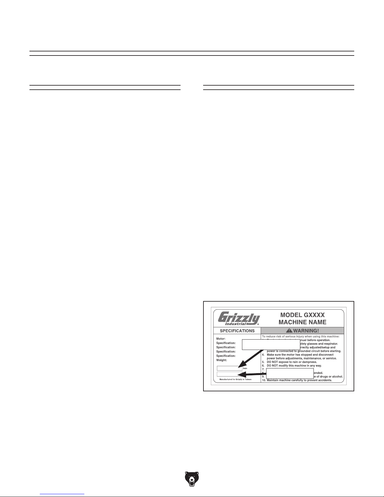
for help. Before calling, please write down the
Manufacture Date
stamped
into the machine ID label (see below). This information helps us determine if updated documentation is available for your machine.
We stand behind our machines. If you have
any questions or need help, use the information
below to contact us. Before contacting, please get
the serial number and manufacture date of your
machine. This will help us help you faster.
We want your feedback on this manual. What did
you like about it? Where could it be improved?
Please take a few minutes to give us feedback.
Email: manuals@grizzly.com
Contact Info
Grizzly Technical Support
1203 Lycoming Mall Circle
Muncy, PA 17756
Phone: (570) 546-9663
Email: techsupport@grizzly.com
Grizzly Documentation Manager
P.O. Box 2069
Bellingham, WA 98227-2069
Manual Accuracy
made every effort to be exact with the
our policy of continuous improvement
sometimes the machine
.
, check our website
e post current
manual updates for free on our website at
.
and Serial Number
Manufacture Date
Serial Number
-2-
Model T10875 (Mfd. Since 01/15)
Controls & Components
To reduce your risk of
serious injury, read this
entire manual BEFORE
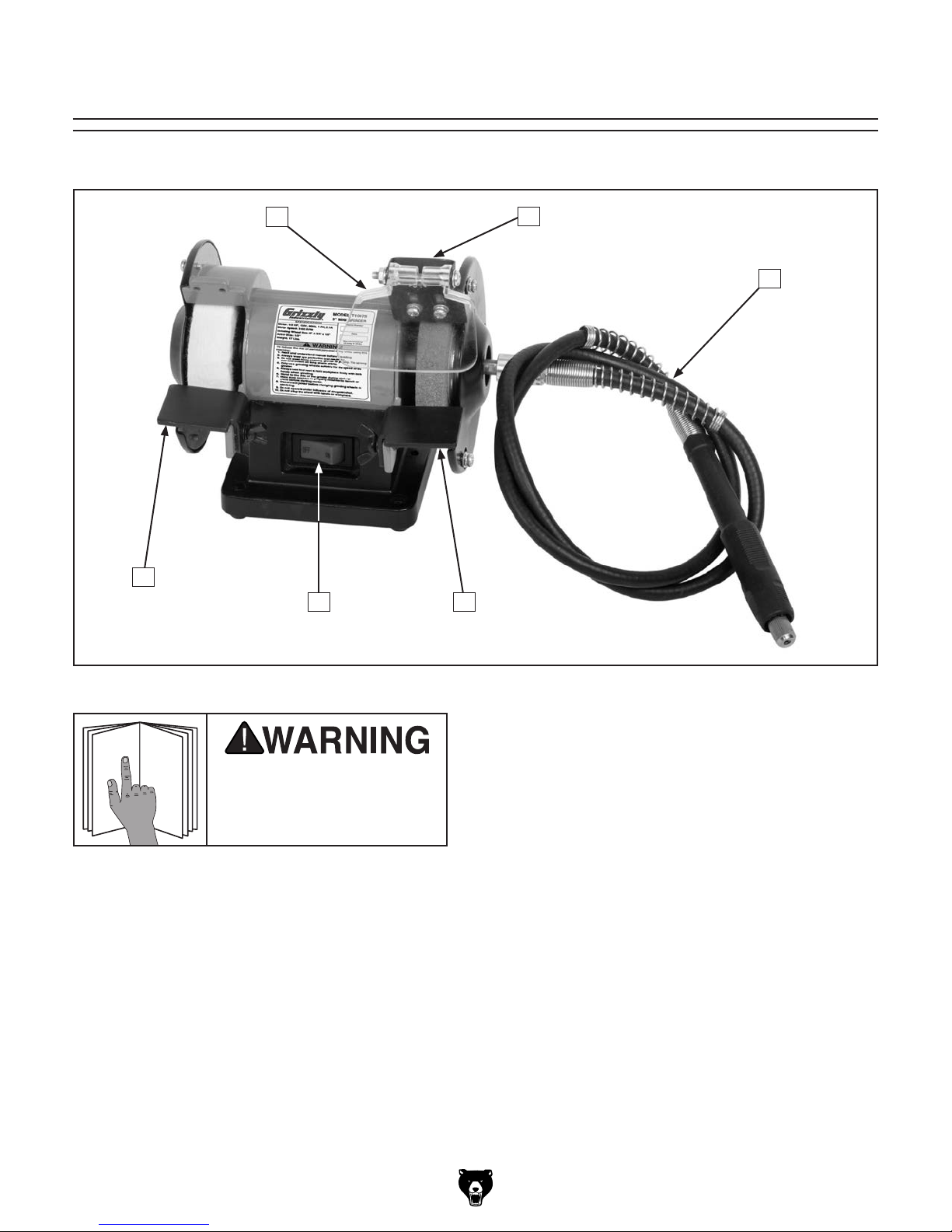
Refer to Figure 1 and the following descriptions to become familiar with the basic controls of this machine.
B
A
F
E
C
D
Figure 1. T10875 controls and components.
using machine.
A. Tool Rest: Provides flat surface to rest
workpiece during operations.
B. Safety Shield: Acts as a protective barrier
against sparks during grinding operations.
This shield is not a substitute for personal
protective equipment.
C. Spark Deflector: Reduces amount of sparks
spraying back toward the operator.
D. Rotating Shaft: Attaches to the right side of
the grinder to provide rotary tool functionality.
E. Wheel Guard: Prevents accidental contact
with grinding wheel, and contains sparks during grinding.
F. ON/OFF Switch: Turns motor ON when
flipped to right; Turns motor OFF when
flipped to left.
Model T10875 (Mfd. Since 01/15)
-3-

Machine Data Sheet
MACHINE DATA
SHEET
Customer Service #: (570) 546-9663 · To Order Call: (800) 523-4777 · Fax #: (800) 438-5901
MODEL T10875 3" MINI GRINDER/BUFFER WITH ROTATING
SHAFT
Product Dimensions:
Weight.................................................................................................................................................................. 5 lbs.
Width (side-to-side) x Depth (front-to-back) x Height.............................................................. 6-3/4 x 5-1/4 x 6-1/4 in.
Footprint (Length x Width)................................................................................................................... 3-1/2 x 3-1/2 in.
Shipping Dimensions:
Type............................................................................................................................................................. Cardboard
Content........................................................................................................................................................... Machine
Weight.................................................................................................................................................................. 6 lbs.
Length x Width x Height........................................................................................................................... 10 x 8 x 7 in.
Electrical:
Power Requirement........................................................................................................... 120V, Single-Phase, 60 Hz
Full-Load Current Rating....................................................................................................................................... 0.4A
Minimum Circuit Size.............................................................................................................................................. 15A
Connection Type....................................................................................................................................... Cord & Plug
Power Cord Included.............................................................................................................................................. Yes
Power Cord Length.......................................................................................................................................... 6-1/2 ft.
Plug Included.......................................................................................................................................................... Yes
Included Plug Type................................................................................................................................................ 5-15
Switch Type............................................................................................................................. Toggle ON/OFF Switch
Motors:
Main
Type..................................................................................................................................................... Induction
Horsepower........................................................................................................................................... 1/14 HP
Phase............................................................................................................................................ Single-Phase
Amps........................................................................................................................................................... 0.4A
Speed................................................................................................................................................ 3450 RPM
Power Transfer ............................................................................................................................... Direct Drive
Bearings..................................................................................................... Shielded & Permanently Lubricated
Main Specifications:
Operation Info
Right Wheel Type..................................................................................................................... Aluminum Oxide
Left Wheel Type......................................................................................................................................... Wool
Wheel Bore............................................................................................................................................... 1/2 in.
Wheel Speed at Maximum Wheel Diameter...................................................................................... 3450 RPM
Construction
Base........................................................................................................................................................... Steel
Work Rest................................................................................................................................................... Steel
Eye Shields.................................................................................................................................. Polycarbonate
-4-
Model T10875 (Mfd. Since 01/15)

SECTION 1: SAFETY
For Your Own Safety, Read Instruction
Manual Before Operating This Machine
The purpose of safety symbols is to attract your attention to possible hazardous conditions.
This manual uses a series of symbols and signal words intended to convey the level of importance of the safety messages. The progression of symbols is described below. Remember that
safety messages by themselves do not eliminate danger and are not a substitute for proper
accident prevention measures. Always use common sense and good judgment.
Indicates an imminently hazardous situation which, if not avoided,
WILL result in death or serious injury.
Indicates a potentially hazardous situation which, if not avoided,
COULD result in death or serious injury.
Indicates a potentially hazardous situation which, if not avoided,
MAY result in minor or moderate injury. It may also be used to alert
against unsafe practices.
This symbol is used to alert the user to useful information about
NOTICE
proper operation of the machine.
Safety Instructions for Machinery
OWNER’S MANUAL. Read and understand this
owner’s manual BEFORE using machine.
TRAINED OPERATORS ONLY. Untrained operators have a higher risk of being hurt or killed.
Only allow trained/supervised people to use this
machine. When machine is not being used, disconnect power, remove switch keys, or lock-out
machine to prevent unauthorized use—especially
around children. Make workshop kid proof!
DANGEROUS ENVIRONMENTS. Do not use
machinery in areas that are wet, cluttered, or have
poor lighting. Operating machinery in these areas
greatly increases the risk of accidents and injury.
MENTAL ALERTNESS REQUIRED. Full mental
alertness is required for safe operation of machinery. Never operate under the influence of drugs or
alcohol, when tired, or when distracted.
ELECTRICAL EQUIPMENT INJURY RISKS. You
can be shocked, burned, or killed by touching live
electrical components or improperly grounded
machinery. To reduce this risk, only allow qualified
service personnel to do electrical installation or
repair work, and always disconnect power before
accessing or exposing electrical equipment.
DISCONNECT POWER FIRST.
nect machine from power supply BEFORE making
adjustments, changing tooling, or servicing machine.
This prevents an injury risk from unintended startup
or contact with live electrical components.
EYE PROTECTION. Always wear ANSI-approved
safety glasses or a face shield when operating or
observing machinery to reduce the risk of eye
injury or blindness from flying particles. Everyday
eyeglasses are NOT approved safety glasses.
Always discon-
Model T10875 (Mfd. Since 01/15)
-5-

WEARING PROPER APPAREL. Do not wear
clothing, apparel or jewelry that can become
entangled in moving parts. Always tie back or
cover long hair. Wear non-slip footwear to avoid
accidental slips, which could cause loss of workpiece control.
HAZARDOUS DUST. Dust created while using
machinery may cause cancer, birth defects, or
long-term respiratory damage. Be aware of dust
hazards associated with each workpiece material,
and always wear a NIOSH-approved respirator to
reduce your risk.
HEARING PROTECTION. Always wear hearing protection when operating or observing loud
machinery. Extended exposure to this noise
without hearing protection can cause permanent
hearing loss.
REMOVE ADJUSTING TOOLS. Tools left on
machinery can become dangerous projectiles
upon startup. Never leave chuck keys, wrenches,
or any other tools on machine. Always verify
removal before starting!
USE CORRECT TOOL FOR THE JOB. Only use
this tool for its intended purpose—do not force
it or an attachment to do a job for which it was
not designed. Never make unapproved modifications—modifying tool or using it differently than
intended may result in malfunction or mechanical
failure that can lead to personal injury or death!
AWKWARD POSITIONS. Keep proper footing
and balance at all times when operating machine.
Do not overreach! Avoid awkward hand positions
that make workpiece control difficult or increase
the risk of accidental injury.
CHILDREN & BYSTANDERS. Keep children and
bystanders at a safe distance from the work area.
Stop using machine if they become a distraction.
FORCING MACHINERY. Do not force machine.
It will do the job safer and better at the rate for
which it was designed.
NEVER STAND ON MACHINE. Serious injury
may occur if machine is tipped or if the cutting
tool is unintentionally contacted.
STABLE MACHINE. Unexpected movement during operation greatly increases risk of injury or
loss of control. Before starting, verify machine is
stable and mobile base (if used) is locked.
USE RECOMMENDED ACCESSORIES. Consult
this owner’s manual or the manufacturer for recommended accessories. Using improper accessories will increase the risk of serious injury.
UNATTENDED OPERATION. To reduce the
risk of accidental injury, turn machine OFF and
ensure all moving parts completely stop before
walking away. Never leave machine running
while unattended.
MAINTAIN WITH CARE. Follow all maintenance
instructions and lubrication schedules to keep
machine in good working condition. A machine
that is improperly maintained could malfunction,
leading to serious personal injury or death.
CHECK DAMAGED PARTS. Regularly inspect
machine for any condition that may affect safe
operation. Immediately repair or replace damaged
or mis-adjusted parts before operating machine.
MAINTAIN POWER CORDS. When disconnecting cord-connected machines from power, grab
and pull the plug—NOT the cord. Pulling the cord
may damage the wires inside. Do not handle
cord/plug with wet hands. Avoid cord damage by
keeping it away from heated surfaces, high traffic
areas, harsh chemicals, and wet/damp locations.
GUARDS & COVERS. Guards and covers reduce
accidental contact with moving parts or flying
debris. Make sure they are properly installed,
undamaged, and working correctly.
-6-
EXPERIENCING DIFFICULTIES. If at any time
you experience difficulties performing the intended operation, stop using the machine! Contact our
Technical Support at (570) 546-9663.
Model T10875 (Mfd. Since 01/15)

Additional Safety for Grinders
remove skin, or entanglement/amputation injuries can occur from being caught in moving
Serious injury or death can occur from impact injuries. Rotating grinding wheels can easily
parts or in-running pinch points. Flying sparks can ignite explosive or flammable materials. To
minimize risk of getting hurt or killed, anyone operating machine MUST completely heed hazards
and warnings below.
SAFE MOUNTING & WORK AREA. An unse-
cured grinder may become dangerously out of
EYE SHIELDS. Place eye shields close to grind-
ing wheel and re-adjust as wheel wears down.
control during operation. Before use, verify grinder
is FIRMLY secured in a location free of explosive
or flammable materials.
TOOL REST POSITION. If tool rest is too far
away from wheel, workpiece may be pulled down,
causing loss of control and pulling your hand into
STARTING GRINDER. If a wheel is damaged,
it will usually fly apart shortly after start-up. To
protect yourself, always stand to side of grinder
when turning it ON and allow it to run for at least
grinding wheel. Keep tool rest within
wheel when operating. Replace grinding wheel
1
when tool rest gap is wider than
⁄8 ” and no addi-
tional adjustment can be made.
one minute before standing in front of it.
HAND & WHEEL CONTACT. Keep a firm grip
VISUAL INSPECTION. Verify that grinding wheels
are free of cracks, chips, or dents in wheel surface
before installing. Do not use wheel if it has any
of these problems or it could break apart during
operation.
on workpiece and position your hands a safe dis-
tance away when grinding. Anticipate when work-
piece will heat up, and cool it before it becomes
too hot to hold, or use an appropriate clamp.
Avoid wearing gloves as they may get caught
in grinding wheel and cause even more serious
RING TEST. Perform a “ring test” on grinding
entanglement injuries.
wheels before installation to ensure they are safe
to use. A wheel that does NOT pass ring test may
break or fly apart during operation.
WHEEL FLANGES. Only use flanges included
with grinder when mounting wheels. Other flang-
es may not properly secure wheel and cause an
WHEEL SPEED RATING. Wheels oper-
ated at a faster speed than rated for may
break apart during operation. Before
mounting a new wheel, be sure wheel
accident. Do not use warped or damaged flanges,
and always use paper discs (blotters) between
wheels and flanges to reduce risk of flanges
cracking wheel when tightened.
RPM rating is equal or higher than speed of
grinder. Never use unmarked wheels.
EYE, FACE, & LUNG PROTECTION. Grinding
ejects small particles at a high rate of speed.
VIBRATING WHEEL. Never use a wheel that
vibrates. Replace wheel or shaft bearings immediately.
These particles can cause blindness, skin injuries
or respiratory damage. ALWAYS wear approved
clothing, safety goggles, face shield, and a respi-
rator for type of grinding to be done.
SPARK DEFLECTOR GAP. Keep gap between
end of spark deflector and grinding wheel
1
between
⁄8 ” and 1⁄4”. If the gap is larger, excessive
sparks and abrasives can be expelled toward the
operator.
SIDE & TOP GRINDING. Grinding on side of
wheels can cause them to crack and burst—
unless wheel is rated for side grinding. Grinding
on top of wheels greatly increases risk of workpiece kickback. Always grind on downward part
SPINDLE NUT. Only tighten wheel spindle nut
of wheel.
enough to drive wheel and prevent slippage.
1
⁄8” from
Model T10875 (Mfd. Since 01/15)
-7-

Additional Safety for Buffers
EYE/FACE PROTECTION. Always wear eye pro-
tection or a face shield when operating the buffer.
LUNG PROTECTION. Always wear a respirator
when using this machine. Workpiece and buffing
compound dust may cause allergies or long-term
respiratory health problems.
MOUNTING TO BENCH/STAND. An unsecured
buffer may become dangerously out of control
during operation. Make sure buffer is FIRMLY
secured to a bench/stand before use.
CORRECT ACCESSORIES AND USE. The buffer is only designed for buffing and polishing.
Never exceed the maximum speed listed on each
buffing/polishing wheel.
WORKPIECE CONTROL. If you cannot hold
small workpieces securely, do not buff them with
this machine. Secure them with clamps or similar
jigs or use a different buffer.
OPERATOR POSITION. Do not stand directly in
front of the buffer wheel when turning the machine
ON, or when buffing. Do not buff material at the
rear of the machine.
WORKPIECE SELECTION. Always inspect the
condition of your workpiece. DO NOT buff pieces
with loose knots, large splinters, sharp edges, and
DO NOT buff knives, cable, chain or other potentially dangerous objects that may be grabbed by
the buffing wheel and thrown at the operator.
WORKPIECE FEED. Allow the wheel to reach
full speed, then slowly ease the workpiece into
the buffing wheel, holding it in front of and
slightly below the wheel center. Do not place
the workpiece on the top or sides of the buffing
wheel and do not place an edge or corner of
the workpiece against the buffing wheel, or jam
it against the wheel. The workpiece may eject
toward the operator or be torn from the operator’s
hands, causing serious personal injury.
HAND/WHEEL CONTACT. Do not allow your
hands to come into contact with the buffing wheel.
Abrasive accessories can remove skin fast. Keep
a firm grip on the workpiece and position your
hands at a safe distance away when buffing.
Avoid wearing gloves as they may get caught in
the buffing wheel and cause entanglement injuries.
ADJUSTMENTS/MAINTENANCE. Make sure
your buffer is turned OFF, disconnected from its
power source, and all moving parts have come to
a complete stop before starting any inspection,
adjustment, or maintenance procedure.
AVOIDING ENTANGLEMENT. Keep long hair
and loose clothing articles such as sleeves, belts,
and jewelry items away from the buffer.
Like all machinery there is potential danger when operating this bench grinder.
Accidents are frequently caused by lack of
familiarity or failure to pay attention. Use
this bench grinder with respect and caution
to lessen the possibility of operator injury. If
normal safety precautions are overlooked or
ignored, serious personal injury may occur.
-8-
No list of safety guidelines can be complete.
Every shop environment is different. Always
consider safety first, as it applies to your
individual working conditions. Use this and
other machinery with caution and respect.
Failure to do so could result in serious personal injury, damage to equipment, or poor
work results.
Model T10875 (Mfd. Since 01/15)

SECTION 2: POWER SUPPLY
Before installing the machine, consider the availability and proximity of the required power supply
circuit. If an existing circuit does not meet the
requirements for this machine, a new circuit must
be installed. To minimize the risk of electrocution,
fire, or equipment damage, installation work and
electrical wiring must be done by an electrician or
qualified service personnel in accordance with all
applicable codes and standards.
Electrocution, fire, or
equipment damage may
occur if machine is not
correctly grounded and
connected to the power
The full-load current rating is the amperage a
machine draws at 100% of the rated output power.
On machines with multiple motors, this is the
amperage drawn by the largest motor or sum of all
motors and electrical devices that might operate
at one time during normal operations.
The full-load current is not the maximum amount
of amps that the machine will draw. If the machine
is overloaded, it will draw additional amps beyond
the full-load rating.
If the machine is overloaded for a sufficient length
of time, damage, overheating, or fire may result—
especially if connected to an undersized circuit.
To reduce the risk of these hazards, avoid overloading the machine during operation and make
sure it is connected to a power supply circuit that
meets the specified circuit requirements.
For your own safety and protection of
Note: Circuit requirements in this manual apply to
a dedicated circuit—where only one machine will
be running on the circuit at a time. If machine will
be connected to a shared circuit where multiple
machines may be running at the same time, consult an electrician or qualified service personnel to
ensure circuit is properly sized for safe operation.
A power supply circuit includes all electrical
equipment between the breaker box or fuse panel
in the building and the machine. The power supply circuit used for this machine must be sized to
safely handle the full-load current drawn from the
machine for an extended period of time. (If this
machine is connected to a circuit protected by
fuses, use a time delay fuse marked D.)
This machine is prewired to operate on a power
supply circuit that has a verified ground and meets
the following requirements:
Availability
Serious injury could occur if you connect
the machine to power before completing the
setup process. DO NOT connect to power
until instructed later in this manual.
120V Circuit Requirements
Nominal Voltage ........................................120V
Cycle ..........................................................60 Hz
Phase ........................................... Single-Phase
Power Supply Circuit ......................... 15 Amps
supply.
Full-Load Current Rating
Full-Load Current Rating at 120V .... 0.4 Amps
Model T10875 (Mfd. Since 01/15)
property, consult an electrician if you are
unsure about wiring practices or electrical
codes in your area.
-9-

Improper connection of the equipment-grounding
wire can result in a risk of electric shock. The
wire with green insulation (with or without yellow
stripes) is the equipment-grounding wire. If repair
or replacement of the power cord or plug is necessary, do not connect the equipment-grounding
wire to a live (current carrying) terminal.
Check with a qualified electrician or service personnel if you do not understand these grounding
requirements, or if you are in doubt about whether
the tool is properly grounded. If you ever notice
that a cord or plug is damaged or worn, disconnect it from power, and immediately replace it with
a new one.
We do not recommend using an extension cord
with this machine.
cord, only use it if absolutely necessary and only
on a temporary basis.
Extension cords cause voltage drop, which can
damage electrical components and shorten motor
life. Voltage drop increases as the extension cord
size gets longer and the gauge size gets smaller
(higher gauge numbers indicate smaller sizes).
Any extension cord used with this machine must
be in good condition and contain a ground wire
and matching plug/receptacle. Additionally, it must
meet the following size requirements:
Grounding & Plug Requirements
it will not fit the outlet, have a qualified
electrician install the proper outlet with a
This machine MUST be grounded. In the event
of certain malfunctions or breakdowns, grounding
reduces the risk of electric shock by providing a
path of least resistance for electric current.
This machine is equipped with a power cord that
has an equipment-grounding wire and a grounding
plug. Only insert plug into a matching receptacle
(outlet) that is properly installed and grounded in
accordance with all local codes and ordinances.
DO NOT modify the provided plug!
GROUNDED
5-15 RECEPTACLE
Grounding Prong
5-15 PLUG
Extension Cords
If you must use an extension
Neutral Hot
Figure 2. Typical 5-15 plug and receptacle.
SHOCK HAZARD!
Two-prong outlets do not meet the grounding
requirements for this machine. Do not modify
or use an adapter on the plug provided—if
verified ground.
-10 -
Minimum Gauge Size ...........................16 AWG
Maximum Length (Shorter is Better).......50 ft.
Model T10875 (Mfd. Since 01/15)
 Loading...