

Page 1

MODEL T10010
WET GRINDER
COPYRIGHT © NOVEMBER, 2007 BY GRIZZLY INDUSTRIAL, INC. REV. JANUARY, 2012 (ST)
WARNING: NO PORTION OF THIS MANUAL MAY BE REPRODUCED IN ANY SHAPE
OR FORM WITHOUT THE WRITTEN APPROVAL OF GRIZZLY INDUSTRIAL, INC.
(FOR MODELS MANUFACTURED SINCE 3/10) #JB9991 PRINTED IN CHINA
Page 2

This manual provides critical safety instructions on the proper setup,
operation, maintenance, and service of this machine/tool. Save this
document, refer to it often, and use it to instruct other operators.
Failure to read, understand and follow the instructions in this manual
may result in fire or serious personal injury—including amputation,
electrocution, or death.
The owner of this machine/tool is solely responsible for its safe use.
This responsibility includes but is not limited to proper installation in
a safe environment, personnel training and usage authorization,
proper inspection and maintenance, manual availability and comprehension, application of safety devices, cutting/sanding/grinding tool
integrity, and the usage of personal protective equipment.
The manufacturer will not be held liable for injury or property damage
from negligence, improper training, machine modifications or misuse.
Some dust created by power sanding, sawing, grinding, drilling, and
other construction activities contains chemicals known to the State
of California to cause cancer, birth defects or other reproductive
harm. Some examples of these chemicals are:
• Lead from lead-based paints.
• Crystalline silica from bricks, cement and other masonry products.
• Arsenic and chromium from chemically-treated lumber.
Your risk from these exposures varies, depending on how often you
do this type of work. To reduce your exposure to these chemicals:
Work in a well ventilated area, and work with approved safety equipment, such as those dust masks that are specially designed to filter
out microscopic particles.
Page 3

Table of Contents
INTRODUCTION ...............................................................................................................2
Manual Accuracy ........................................................................................................2
SECTION 1: SAFETY .......................................................................................................3
SECTION 2: POWER SUPPLY ........................................................................................7
SECTION 3: SETUP .........................................................................................................9
Unpacking ...................................................................................................................9
Inventory .....................................................................................................................9
Site Considerations ...................................................................................................10
Wheel Inspection ......................................................................................................10
Test Run ...................................................................................................................12
SECTION 4: OPERATIONS ...........................................................................................13
Grinding Tips ............................................................................................................13
Positioning the Universal Support ............................................................................14
Grinding Jig...............................................................................................................15
Water Reservoir ........................................................................................................16
Angle Guide ..............................................................................................................17
Sharpening ...............................................................................................................18
SECTION 5: ACCESSORIES .........................................................................................19
SECTION 6: MAINTENANCE ........................................................................................21
Wheel Dressing ........................................................................................................21
Grinding Wheels .......................................................................................................21
Wheel Replacement .................................................................................................21
Water Reservoir ........................................................................................................21
SECTION 7: SERVICE ...................................................................................................22
Troubleshooting ........................................................................................................22
SECTION 8: WIRING......................................................................................................24
Wiring Safety Instructions .........................................................................................24
Wiring Diagram .........................................................................................................25
Main Breakdown .......................................................................................................26
Main Parts List ..........................................................................................................27
Machine Labels Breakdown & Parts List ..................................................................28
WARRANTY ...................................................................................................................31
Model T10010 (Mfg. Since 3/10)
-1-
Page 4
INTRODUCTION
We are proud to offer this manual with your new
machine! We've made every effort to be exact
with the instructions, specifications, drawings,
and photographs of the machine we used when
writing this manual. However, sometimes we still
make an occasional mistake.
Also, owing to our policy of continuous improve-
ment, your machine may not exactly match the
manual. If you find this to be the case, and the dif-
ference between the manual and machine leaves
you in doubt, check our website for the latest
manual update or call technical support for help.
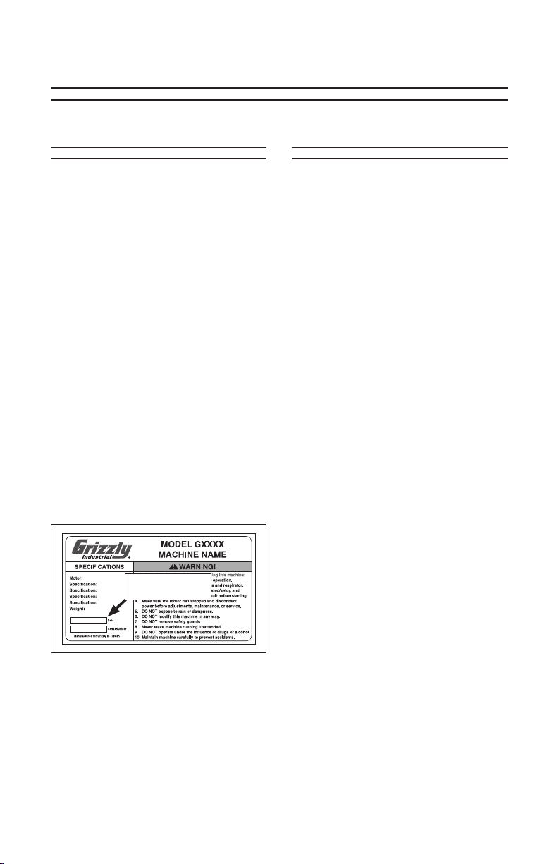
Before calling, find the manufacture date of your
machine by looking at the date stamped into the
machine ID label (see below). This will help us
determine if the manual version you received
matches the manufacture date of your machine.
Manufacture Date
of Your Machine
Manual Accuracy Contact Info
We are proud to offer this document with
your new machine! We've made every
effort to be exact with the instructions,
specifications, drawings, and photographs
of the machine we used when writing
this manual. However, sometimes we still
make an occasional mistake.
Also, owing to our policy of continuous
improvement, your machine may not
exactly match the manual. If you find this
to be the case, and the difference between
the manual and machine leaves you in
doubt, immediately call our technical support for updates or clarification.
Before calling, find the manufacture date
of your machine by looking at the date
stamped into the machine ID label (see
below). This will help us determine if the
manual version you received matches the
manufacture date of your machine.
For your convenience, we post all available documentation on our website at
www.grizzly.com. Any updates to this document will be reflected on our website as
soon as complete.
We stand behind our tools. If you have any
questions or need help, use the information below to contact us. Before contacting, please get the serial number and
manufacture date of your machine. This
will help us help you faster.
Grizzly Industrial, Inc.
1203 Lycoming Mall Circle
Muncy, PA 17756
Phone: (570) 546-9663
E-Mail: techsupport@grizzly.com
We want your feedback on this manual.
What did you like about it? Where could it
be improved? Please take a few minutes to
give us feedback.
Grizzly Documentation Manager
P.O. Box 2069
Bellingham, WA 98227-2069
Email: manuals@grizzly.com
-2-
Model T10010 (Mfg. Since 3/10)
Page 5
Safety
SECTION 1: SAFETY
For Your Own Safety Read Instruction Manual
Before Operating This Equipment
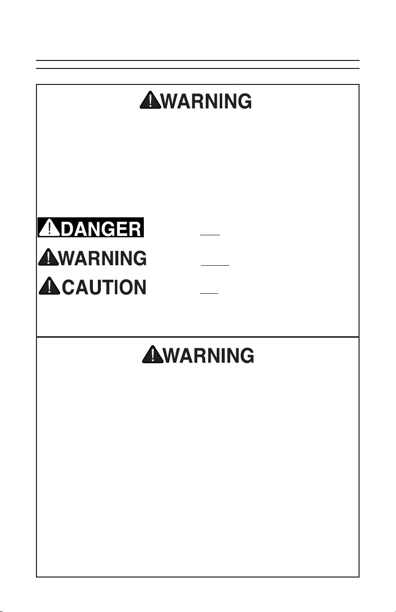
The purpose of safety symbols is to attract your attention to possible hazardous conditions. This manual uses a series of symbols and signal words which
are intended to convey the level of importance of the safety messages. The
progression of symbols is described below. Remember that safety messages by
themselves do not eliminate danger and are not a substitute for proper accident
prevention measures.
Indicates an imminently hazardous situation which, if
not avoided, WILL result in death or serious injury.
Indicates a potentially hazardous situation which, if
not avoided, COULD result in death or serious injury.
Indicates a potentially hazardous situation which, if
not avoided, MAY result in minor or moderate injury.
It may also be used to alert against unsafe practices.
NOTICE
This symbol is used to alert the user to useful information about proper operation of the equipment.
Safety Instructions for Machinery
1. READ THROUGH THE ENTIRE
MANUAL BEFORE STARTING
MACHINERY. Machinery presents
serious injury hazards to untrained
users.
2. ALWAYS USE ANSI APPROVED
SAFETY GLASSES WHEN
OPERATING MACHINERY.
Everyday eyeglasses only have
impact resistant lenses, they are
NOT safety glasses.
3. ALWAYS WEAR A NIOSH
APPROVED RESPIRATOR WHEN
OPERATING MACHINERY THAT
PRODUCES DUST. Wood dust is
a carcinogen and can cause cancer
and severe respiratory illnesses.
Model T10010 (Mfg. Since 3/10)
4. ALWAYS USE HEARING
PROTECTION WHEN OPERATING
MACHINERY. Machinery noise can
cause permanent hearing damage.
5. WEAR PROPER APPAREL. DO
NOT wear loose clothing, gloves,
neckties, rings, or jewelry which
may get caught in moving parts.
Wear protective hair covering to
contain long hair and wear non-slip
footwear.
6. NEVER OPERATE MACHINERY
WHEN TIRED, OR UNDER THE
INFLUENCE OF DRUGS OR
ALCOHOL. Be mentally alert at all
times when running machinery.
-3-
Page 6

7. ONLY ALLOW TRAINED AND
PROPERLY SUPERVISED PERSONNEL TO OPERATE MACHINERY. Make sure operation instruc-
tions are safe and clearly understood.
8. KEEP CHILDREN AND VISITORS
AWAY. Keep all children and visi-
tors a safe distance from the work
area.
9. MAKE WORKSHOP CHILD
PROOF. Use padlocks, master
switches, and remove switch keys.
10. NEVER LEAVE WHEN MACHINE
IS RUNNING. Turn power OFF
and allow all moving parts to come
to a complete stop before leaving
machine unattended.
17. REMOVE ADJUSTING KEYS
AND WRENCHES. Make a habit
of checking for keys and adjusting
wrenches before turning machinery
ON.
18. CHECK FOR DAMAGED PARTS
BEFORE USING MACHINERY.
Check for binding and alignment
of parts, broken parts, part mounting, loose bolts, and any other
conditions that may affect machine
operation. Repair or replace damaged parts.
19. US E RE C O M M END E D
ACCESSORIES. Refer to the
instruction manual for recommended accessories. The use of
improper accessories may cause
risk of injury.
11. DO NOT USE IN DANGEROUS
ENVIRONMENTS. DO NOT use
machinery in damp, wet locations,
or where any flammable or noxious
fumes may exist.
12. KEEP WORK AREA CLEAN AND
WELL LIT. Clutter and dark shad-
ows may cause accidents.
13. USE A GROUNDED EXTENSION
CORD RATED FOR THE MACHINE
AMPERAGE. Undersized cords
overheat and lose power. Replace
extension cords if they become
damaged. DO NOT use extension
cords for 220V machinery.
14.
ALWAYS DISCONNECT FROM
POWER SOURCE BEFORE
SERVICING MACHINERY. Make
sure switch is in
reconnecting.
15. MAINTAIN MACHINERY WITH
CARE. Keep blades sharp and
clean for best and safest performance. Follow instructions for lubricating and changing accessories.
16. MAKE SURE GUARDS ARE IN
PLACE AND WORK CORRECTLY
BEFORE USING MACHINERY.
OFF
position before
20. DO NOT FORCE MACHINERY.
Work at the speed for which
the machine or accessory was
designed.
21. SECURE WORKPIECE. Use
clamps or a vise to hold the
workpiece when practical. A secured
workpiece protects your hands and
frees both hands to operate the
machine.
22. DO NOT OVERREACH. Keep
proper footing and balance at all
times.
23. MANY MACHINES WILL EJECT
THE WORKPIECE TOWARD THE
OPERATOR. Know and avoid con-
ditions that cause the workpiece to
"kickback."
24. ALWAYS LOCK MOBILE BASES
(IF USED) BEFORE OPERATING
MACHINERY.
25. BE AWARE THAT CERTAIN
WOODS MAY CAUSE AN ALLERGIC REACTION in people and ani-
mals, especially when exposed to
fine dust. Make sure you know
what type of wood dust you will be
exposed to and always wear an
approved respirator.
-4-
Model T10010 (Mfg. Since 3/10)
Page 7

Additional Safety Instructions for Grinders
1. EYE PROTECTION. Grinding causes
small particles to become airborne at
a high rate of speed that could impact
your eyes, causing severe injury.
ALWAYS wear safety glasses when
using this machine.
6. LUNG PROTECTION. Grinding pro-
duces hazardous dust, which may
cause long-term respiratory problems
if breathed. Always wear a NIOSH
approved dust mask or respirator
when grinding.
2. WHEEL SPEED RATING. Wheels
operated at a faster speed than rated
for may break or fly apart and strike
you with great force. Before mounting a
new wheel, be sure the wheel RPM rating is equal to or higher than the speed
of the grinder.
3. WHEEL FLANGES. Only use the
flanges included with the grinder when
mounting wheels. Other flanges may
not properly secure the wheel or could
cause it to break apart, resulting in serious impact injuries.
4. RING TEST. Perform a “ring test” on
grinding wheels before installation to
ensure that they are safe to use. A
wheel that does not pass the ring test
may break or fly apart during operation,
resulting in serious impact injuries.
5. TRANSPORT. Carry the grinder by
holding underneath the base. DO NOT
use the universal support as a handle.
It can slide out, allowing the grinder to
fall and cause crushing injuries and
property damage.
7. SIDE GRINDING. Grinding on the
side of wheels can cause them to
break and fly apart, resulting in serious impact injuries.—unless the wheel
is rated for side grinding.
8. HAND/WHEEL CONTACT. Grinding
wheels have the capability of removing a lot of skin fast. Keep a firm grip
on the workpiece and position your
hands at a safe distance away when
grinding. Avoid wearing gloves, as
they may get caught in the grinding
wheel and cause even more serious
entanglement injuries.
9. TOOL REST POSITION. If the universal support tool rest or jig is too far
away from the wheel, the workpiece
may be pulled down, causing loss of
control and pulling your hand into the
grinding wheel. Keep the the universal
support or jig within 1⁄8" from the wheel
when operating.
Model T10010 (Mfg. Since 3/10)
-5-
Page 8

MODEL T10010
WET GRINDER
Customer Service #: (570) 546-9663 • To Order Call: (800) 523-4777 • Fax #: (800) 438-5901
MACHINE DATA
SHEET
Overall Dimensions:
Height ................................................................................................................................................................................... 13"
Width .................................................................................................................................................................................... 17"
Depth ..................................................................................................................................................................................... 13"
Net Weight .......................................................................................................................................................................41 lbs.
Footprint .................................................................................................................................................................... 13" x 10¾"
Main Specifications:
Arbor Diameter ................................................................................................................................................................. 12mm
Grinding Wheel Grit ............................................................................................................................................................ 220
Grinding Wheel Size ..........................................................................................................................250mm x 50mm x 12mm
Grinding Wheel Material ................................................................................................................................. Aluminum Oxide
Stropping Wheel Size ......................................................................................................................................200mm x 30mm
Stropping Wheel Material ..................................................................................................................................... ABS/Leather
Wheel Speed ............................................................................................................................................................. 110 RPM
Motor:
Type ....................................................................................................................................... TEFC Capacitor Start Induction
Horsepower ...................................................................................................................................................................... ¼ HP
Phase/Voltage ........................................................................................................................................................ Single/120V
Amps .................................................................................................................................................................................... 3A
Cycle/RPM ......................................................................................................................................................60Hz/1725 RPM
Other:
Country of Origin ............................................................................................................................................................... China
Warranty ........................................................................................................................................................................... 1 Year
Serial Number Location ................................................................................................................... Machine ID Label on Front
Assembly Time ......................................................................................................................................................... 10 Minutes
Features:
Universal Tool Support 12mm
Paddle Switch w/ Disabling Key
Water Reservoir
Included 220 Grit Aluminum Oxide Grinding Wheel
Included Leather Stropping Wheel
Included Stropping Paste
Included Angle Guide
Includes T20880 Straight Edge Jig
Specifications
-6-
Model T10010 (Mfg. Since 3/10)
Page 9
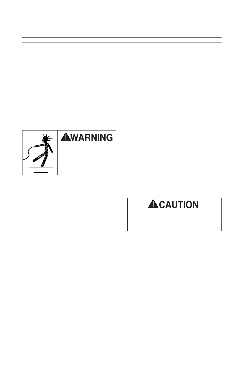
Electrocution, fire, or
equipment damage may
occur if machine is not
correctly grounded and
connected to the power
supply.
For your own safety and protection of
property, consult a qualified electrician if
you are unsure about wiring practices or
electrical codes in your area.
SECTION 2: POWER SUPPLY
Availability
Before installing the machine, consider the
availability and proximity of the required
power supply circuit. If an existing circuit
does not meet the requirements for this
machine, a new circuit must be installed.
To minimize the risk of electrocution, fire,
or equipment damage, installation work
and electrical wiring must be done by a
qualified electrician in accordance with all
applicable codes and standards.
Full Load Current Rating
The full-load current rating is the amperage a machine draws at 100% of the rated
output power. On machines with multiple
motors, this is the amperage drawn by the
largest motor or the sum of all motors and
electrical devices that might operate at
one time during normal operations.
Full-Load Current Rating ............ 3 Amps
The full-load current is not the maximum
amount of amps that the machine will
draw. If the machine is overloaded, it will
draw additional amps beyond the full-load
rating.
Circuit Requirements
This machine is prewired to operate on
a 110V power supply circuit that has a
verified ground and meets the following
requirements:
Nominal Voltage ...............................110V
Cycle .................................................. 60Hz
Phase ...................................Single-Phase
Minimum Circuit Size .........................15A
A power supply circuit includes all electrical equipment between the breaker box
or fuse panel in the building and the
machine. The power supply circuit used
for this machine must be sized to safely
handle the full-load current drawn from the
machine for an extended period of time.
(If this machine is connected to a circuit
protected by fuses, use a time delay fuse
marked D.)
Note: The circuit requirements listed in
this manual apply to a dedicated circuit—
where only one machine will be running at
a time. If this machine will be connected to
a shared circuit where multiple machines
will be running at the same time, consult a
qualified electrician to ensure that the circuit is properly sized for safe operation.
If the machine is overloaded for a sufficient
length of time, damage, overheating, or
fire may result—especially if connected to
an undersized circuit. To reduce the risk
of these hazards, avoid overloading the
machine during operation and make sure
it is connected to a power supply circuit
that meets the requirements in the following section.
Model T10010 (Mfg. Since 3/10)
-7-
Page 10
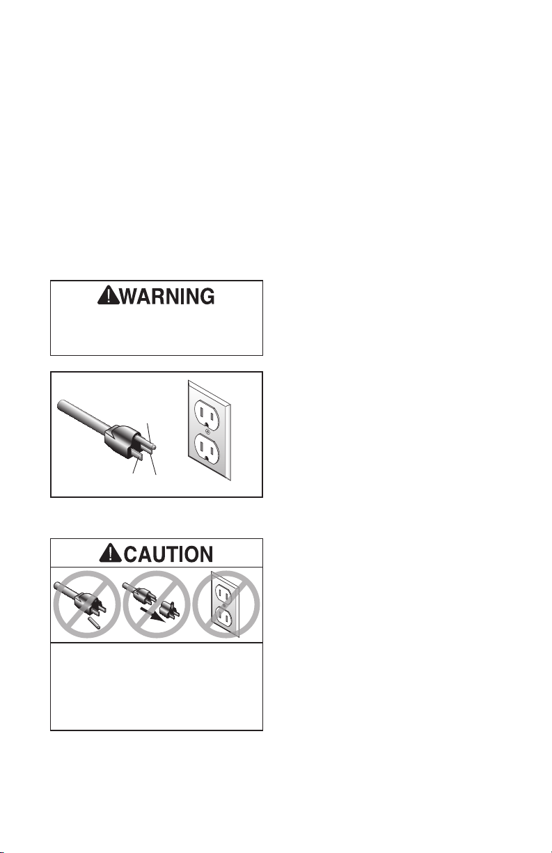
Grounding & Plug Requirements
Grounding Prong
Neutral Hot
5-15 PLUG
GROUNDED
5-15 RECEPTACLE
Serious injury could occur if you connect
the machine to power before completing the
setup process. DO NOT connect to power
until instructed later in this manual.
SHOCK HAZARD!
Two-prong outlets do not meet the grounding
requirements for this machine. Do not modify
or use an adapter on the plug provided—if
it will not fit the outlet, have a qualified
electrician install the proper outlet with a
verified ground.
This machine MUST be grounded. In the
event of certain malfunctions or breakdowns, grounding reduces the risk of
electric shock by providing a path of least
resistance for electric current.
This machine is equipped with a power
cord that has an equipment-grounding wire
and a grounded plug (similar to the figure
below). The plug must only be inserted into
a matching receptacle (outlet) that is properly installed and grounded in accordance
with all local codes and ordinances.
Figure 1. Typical 5-15 plug and
receptacle.
Improper connection of the equipmentgrounding wire can result in a risk of
electric shock. The wire with green insulation (with or without yellow stripes) is
the equipment-grounding wire. If repair or
replacement of the power cord or plug is
necessary, do not connect the equipmentgrounding wire to a live (current carrying)
terminal.
Check with a qualified electrician or service personnel if you do not understand
these grounding requirements, or if you
are in doubt about whether the tool is
properly grounded. If you ever notice that
a cord or plug is damaged or worn, disconnect if from power, and immediately
replace it with a new one.
Extension Cords
We do not recommend using an extension
cord with this machine. If you must use an
extension cord, only use it if absolutely
necessary and only on a temporary basis.
Extension cords cause voltage drop, which
may damage electrical components and
shorten motor life. Voltage drop increases
as the extension cord size gets longer and
the gauge size gets smaller (higher gauge
numbers indicate smaller sizes).
-8-
Any extension cord used with this machine
must contain a ground wire, match the
required plug and receptacle, and meet
the following requirements:
Minimum Gauge Size ................. 16 AWG
Maximum Length .............................. 50 ft.
Model T10010 (Mfg. Since 3/10)
Page 11
SECTION 3: SETUP
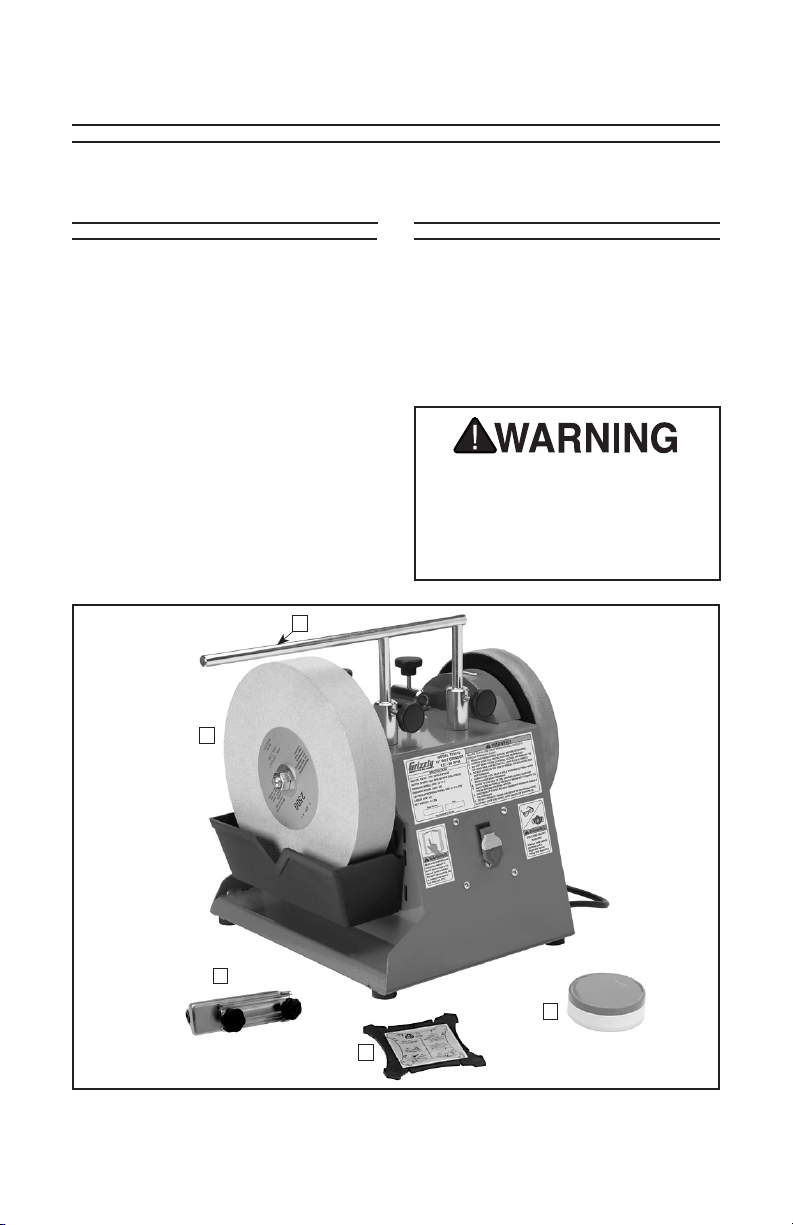
Unpacking Inventory
The Model T10010 was carefully packed
when it left our warehouse. If you discover
any par ts are damaged after you have
signed for delivery, please immediately
call Customer Service at (570) 546-9663
for advice. Save the containers and all
packing materials for possible inspection
by the carrier or its agent. Otherwise, filing
a freight claim can be difficult. When you
are completely satisfied with the condition
of the shipment, you should inventory the
contents.
E
A
Model T10010 Inventory (Figure 2)
A. T10010 Wet Grinder .......................... 1
B. Grinding Jig ........................................ 1
C. Angle Guide ....................................... 1
D. Polishing/Honing Paste ...................... 1
E. Universal Support .............................. 1
The Model T10010 Wet Grinder weighs
41 pounds. DO NOT over-exert yourself while unpacking or moving the
grinder. Use proper lifting techniques
to prevent injury.
B
Figure 2. Model T10010 inventory.
Model T10010 (Mfg. Since 3/10)
D
C
-9-
Page 12

Site Considerations
13"
17"
STOP
Rated 3500 RPM
Make sure your grinder is not
faster than the rated RPM of this wheel
WARNING
Grinding can be dangerous
Visually inspect this wheel
for cracks, nicks,chips
Type-1
Aluminum
Oxide
60 Grit
Grade L
Vitrified Bond
Wheel Inspection
Bench Load
Refer to the Machine Data Sheet on
Page 6 for the weight and size specifica-
tions of the machine. Some workbenches
may require additional reinforcement to
support both the machine and the forces
applied during use.
Placement Location
See Figure 3 for the minimum working
clearances. Remember that the Model
T10010 Wet Grinder has no specific front
or back side and must be repositioned
depending on the desired grinding/sharpening/honing action.
Figure 3. Minimum working clearances.
Children and visitors
may be seriously injured
if unsupervised. Lock all
entrances to the shop
when you are away. DO
NOT allow unsupervised
children or visitors in
your shop at any time!
Do not assume that a wheel is in sound
condition just because it is new—damage
can often occur in shipping, with age,
or with prolonged exposure to moisture.
Inspect every wheel for damage.
First, do a Visual Inspection. Look for any
cracks, chips, nicks or dents in the surface
of the wheel. If you see any of these,
DO NOT use the wheel.
Second, do a Ring Test. This test will give
you an indication of any internal damage
that may not be obvious during a visual
inspection.
To perform a Ring Test:
1. Make sure the wheel that you test is
clean and dry; otherwise, you may get
false results.
2. If size permits, balance the wheel with
your finger in the hole. If this is not possible, hang the wheel in the air with a
piece of cord or string looped through
the hole in the center.
3. At the spots shown in Figure 4, gently
tap the wheel with a light non-metallic
device such as the handle of a screwdriver or a wooden mallet.
-10-
Figure 4. Tapping locations when
performing a ring test.
Model T10010 (Mfg. Since 3/10)
Page 13

— An undamaged wheel will emit a
clear metallic ring or “ping” sound
in each of these spots. A damaged
wheel will respond with a dull thud
that has no clear tone.
— If you determine from the ring test
that the wheel is damaged, DO NOT
use it!
Finally, check that the grinding surface
is square. Lower the universal support to
1
⁄16"– 1⁄8" above the grinding wheel. Using
the universal support as a visual guide,
check that the entire top surface of the
grinding wheel is consistent and parallel to the universal support, as shown in
Figure 5. If th is is not the case, se e Wheel
Dressing on Page 21.
Universal
Support
TO AVOID DAMAGING THE
MOTOR, REMOVE STYROFOAM
BLOCK AND WIRE TIE
BEFORE OPERATING
THE GRINDER
.
To prevent the motor from moving and
causing damage during shipping, a styrofoam block and plastic tie wrap have been
inserted in the grinder. You must remove
these items before connecting the grinder
to power. Failure to do this will result in
incorrect operation, may put undue strain
on the motor, may damage machine components, and will void your warranty!
Check
Parallel
Figure 5. Parallel check.
Model T10010 (Mfg. Since 3/10)
Grinding
Surface
To remove the motor shipping support:
1. Make sure the machine is not con-
nected to power.
2. Carefully place the machine on its
back.
3. Locate the plastic tie wrap that secures
the motor to the machine base. It is
looped from the motor shaft to one of
the vent holes in the machine base.
4. Hold the motor to prevent it from swinging, cut and remove the tie wrap,
remove the styrofoam block, then slowly release the motor.
5. Carefully return the motor to the upright
position.
-11 -
Page 14

Test Run
Once the Model T10010 is positioned,
test run the machine to make sure it runs
properly.
6. Listen and watch for abnormal noises or actions. Under normal conditions, the grinder will make a humming
noise, with only minor vibration. A
slight wobble from one or both wheels
is normal and will not affect grinding
performance.
If, during the test run, you cannot easily
locate the source of an unusual noise or
vibration, stop using the machine immediately, then review the Troubleshooting
on Page 21.
If you still cannot remedy a problem, contact our Tech Support at (570) 546-9663
for assistance.
To test run the machine:
1. Make sure you have read the safety
instructions at the beginning of the
manual and that the grinder is set up
properly.
2. Make sure all tools and objects used
during setup are cleared away from the
grinder.
3. Make sure the switch is pushed in to
the OFF position.
4. Connect the grinder to the power
source.
— Investigate and correct strange or
unusual noises or vibrations before
operating the machine further.
Always disconnect the machine from
power when investigating or correcting potential problems.
7. Turn the grinder OFF.
8. Remove the switch disabling key, as
shown in Figure 6, then attempt to turn
the machine ON.
— If the grinder does not start, the
switch disabling feature is working.
— If the grinder starts, stop it. The
switch disabling feature is not working. This safety feature must work
properly before proceeding. Call
Tech Support for help.
5. Pull the bottom of the switch out to turn
the grinder ON. Make sure your hand
stays poised over the switch in case
you need to quickly turn it OFF.
-12-
Figure 6. Removing the switch disabling
key.
9. Re-insert the switch disabling key.
Model T10010 (Mfg. Since 3/10)
Page 15

SECTION 4: OPERATIONS
Damage to your eyes and lungs could
result from using this machine without proper protective gear. Always
wear safety glasses/face shield and
a dust mask/ respirator when operating this machine.
Loose hair and clothing could get caught
in machinery and
cause serious personal injury. Keep
loose clothing and
long hair away from
moving machinery.
Although the Model T10010 Wet
Grinder wheels are designed specifically for slow rotation, there is still the
possibility that blades and tools being
sharpened on either wheel could be
dislodged from your grasp. Be sure
that satisfactory space is allocated
between the grinder and areas where
others are working. Always wear safety glasses and keep the universal
support in the proper position when
grinding or sharpening.
If you have never used this type of
NOTICE
machine or equipment before, WE
STRONGLY RECOMMEND that you
read books, trade magazines, or get
formal training before beginning any
projects. Regardless of the content
in this section, Grizzly Industrial
will not be held liable for accidents
caused by lack of training.
Grinding Tips
The grinder is a safe tool when used properly. In addition to the safety instructions
beginning on Page 2 in this manual, the
most important safety consideration is to
use common sense at all times. What may
be acceptable in one situation, may not be
safe in another.
Here are some tips to keep in mind
while grinding:
• Always be sure the grinding wheel is
wet before grinding by having the reservoir filled and in the proper location.
• Wear the proper protective clothing.
Safety glasses/face shield and a dust
mask should be worn at all times.
• Grasp the workpiece firmly and properly support it on the universal support or grinding jig during operation.
Maintain even pressure and control of
the workpiece when grinding.
Model T10010 (Mfg. Since 3/10)
• Concentrate on the task at hand. STOP
grinding if other people are distracting
you or your mind is on something else.
-13-
Page 16

Positioning the
Universal Support
The Model T10010 Wet Grinder is equipped
with a universal support that serves as
a tool rest and as an attachment point
for task-specific accessories. It can be
attached in two positions, allowing for
grinding with or against the rotation direction of the grinding wheel. The tightening
knobs on each attachment point allow
the universal support to be adjusted and
locked in position, depending on the specific task required.
Working against the rotation removes large
amounts of materials quickly but does not
yield precise results. Use this method for
coarse tools such as axes.
Working with the rotation yields much
more precise results and removes less
material. Use this method for finer tools,
such as knives or car ving tools.
Do not make adjustments while the
machine is running. Disconnect the
grinder from power before attempting
to make adjustments to the universal
support, water reservoir, changing
wheels or the angle guide.
3. Attach the universal support in the ver-
tical mounts, as shown in Figure 7. Be
sure it is securely positioned and will
not move during grinding. Re-connect
the grinder to power.
4. Rest your workpiece on the universal support with the sharpened edge
pointing away from you. Grind your
workpiece in the indicated grinding
area.
Grinding
Area
Universal
Support
Grinding Against Wheel
Rotation
1. DISCONNECT GRINDER FROM
POWER!
2. Position the machine with the ON/OFF
switch facing you.
-14-
Vertical
Mounts
Figure 7. Vertical mount.
NOTICE
The universal support should never
be placed in the vertical mounts
when using the leather stropping
wheel. Working against the direction
of rotation in this case will cause
severe damage to the leather wheel.
Model T10010 (Mfg. Since 3/10)
Page 17

Grinding With Wheel Rotation
1. DISCONNECT GRINDER FROM
POWER!
2. Position the machine with the ON/OFF
switch facing away from you.
3. Attach the universal support in the horizontal mounts as shown in Figure 8.
Be sure it is securely positioned and will
not move during grinding. Reconnect
the machine to power.
Grinding Jig
The grinding jig provided with the wet
grinder is used for securing a variety of
tools, and can be positioned to grind with
and against the wheel rotation.
To mount the grinding jig:
1. DISCONNECT GRINDER FROM
POWER!
4. Rest your workpiece on the universal support with the sharpened edge
pointing away from you. Grind your
workpiece in the indicated grinding
area.
Grinding
Area
Horizontal
Mounts
Figure 8. Horizontal mount.
Universal
Support
2. Slide the grinding jig onto the universal
support, as illustrated in Figure 9.
Tool
(Varies)
Lock
Knobs
Universal
Figure 9. Grinding jig installed.
3. Insert the tool into the jig clamp, then
use the angle guide, as described on
Page 16, to set the grinding angle.
4. Once the grinding angle is set, tighten
both lock knobs to secure the tool in
place.
5. Re-connect the grinder to power and
perform the operation.
Grinding
Jig
Support
Model T10010 (Mfg. Since 3/10)
-15-
Page 18

Water Reservoir
The Model T10010 Wet Grinder is designed
for wet grinding and should never be used
without water.
3. Attach the reservoir to the grinder.
— If the grinder is going to be used
immediately, position the reservoir
in the upper grinding position by
attaching it in the upper slot (see
Figure 11).
Before filling the water reservoir, identify
the high and low reservoir mounting slots,
as shown in Figure 10. These slots allow
the reservoir to be raised during grinding
and lowered when not in use.
The mounting tabs on the reservoir serve
as hooks to attach to the reservoir mounting slots.
Mounting
Tab
Figure 10. Reservoir mounting positions.
Upper Slot
(Grinding)
Lower Slot
(Storage)
NOTICE
DO NOT attempt to use the grinding
wheel without filling the reservoir
with water. Overheating caused by
lack of lubrication could damage the
grinding wheel, as well as the tool
or blade you are grinding. Ensure
that the reservoir is filled with clean
water. Sediment-filled water can
clog the wheel and reduce the effec tiveness of the grinder.
— If the grinder is not going to be used
immediately, position the reservoir in
the lower storage position by attaching it in the lower slot (see Figure
12).
Important: The grinder must never
be stored with the wheel submersed
in water. Leaving part of the wheel
in water will create potential hazards
from being off-balance and damage
from prolonged exposure to water.
Placing the reservoir in the storage
position reduces the likelihood of
these hazards.
Figure 11. Grinding position.
To fill and position the reservoir:
1. DISCONNECT GRINDER FROM
POWER!
2. Remove the reservoir, clean it out (if
necessary), and fill it with water to just
below the V-shaped notch.
-16-
Figure 12. Storage position.
Model T10010 (Mfg. Since 3/10)
Page 19

To use the angle guide:
DO NOT allow the grinding wheel
to stay immersed in water for long
periods of time without running.
The water can cause the wheel to
become waterlogged and unbalanced and may cause sections of
the wheel to break off when the
grinder is started. Always empty or
lower the reservoir to the storage
position after operations.
Here are some tips for using the wet
grinder water reservoir:
• Check the water level before every use
and be sure the wheel is wet before
you begin grinding. DO NOT use the
grinder without water.
• Leaving the grinding wheel stored in
water will cause damage to the wheel
and create potential hazards because
the wheel will become unbalanced.
Once any grinding process is complete,
return the reservoir to the storage position to prevent prolonged water exposure to the wheel.
• Empty, rinse, and refill the reservoir
regularly. This prevents metal and
stone from accumulating in the reservoir.
1. Locate the eight measuring notches on
the angle finder (see Figure 13).
Angle Edge
Workpiece
Desired
Angle Notch
Measuring
Notches
Figure 13. Measuring notches.
2. Find the angle notch that best fits the
tool you wish to grind by placing the
sharpened edge of the workpiece into
each notch.
3. Place the angle guide on the wheel
with the desired angle notch (found in
Step 2) against the wheel and adjacent to the universal support (see
Figure 14).
Correct
Grinding Angle
• Place a magnet in the reservoir to catch
and collect metal filings. This will help
prevent excessive metal accumulation
on the grinding wheel.
Angle Guide
The Model T10010 Wet Grinder comes
with an angle guide to help identify and
maintain the cutting angle on a variety of
tools.
Model T10010 (Mfg. Since 3/10)
Desired
Angle Notch
Figure 14. Angle guide usage.
4. Adjust the positioning of the tool and
the universal support height as necessary so that the sharpened edge of the
tool is flat against both the grinding
wheel and the angle edge on the angle
guide, as shown in Figure 14.
Note: For precision grinding, use the
provided grinding jig (see Page 14).
Angle Edge
Workpiece
-17-
Page 20

Sharpening
The leather stropping wheel on the Model
T10010 and the included abrasive stropping paste can be used to obtain a razor
sharp edge on many tools. Before use,
the stropping wheel must be properly
prepared.
Note: A slight wobble of the stropping
wheel when it is rotating is normal and
does not affect the performance.
The preparations below will be sufficient
for sharpening five to ten tools. If you
notice a drop in sharpening performance
or have sharpened more than ten tools,
repeat as necessary.
To prepare the stropping wheel:
1. DISCONNECT GRINDER FROM
POWER.
2. Secure the universal support in the
horizontal mounts so that sharpening
will be performed with the direction of
rotation.
Never sharpen against the direction
of rotation. The edge of the tool may
dig into the leather wheel, damaging
the wheel and causing the tool to
eject from the machine. This could
result in personal injury or property
damage.
3. Evenly apply a light machine oil to
the leather wheel. Use enough oil to
provide a thorough coating, but not so
much as to saturate the leather and
result in dripping.
4. Apply a thin coat of abrasive honing
paste to the leather wheel using a
wooden spreader or similar device.
Distribute the paste evenly by handturning the wheel while spreading.
5. Connect the machine to power, then
turn it ON and continue to distribute the
paste, still using the wooden spreader.
Move the spreader lightly in a circular
motion across the wheel.
6. Once the paste is evenly distributed,
begin sharpening.
-18-
Model T10010 (Mfg. Since 3/10)
Page 21

SECTION 5: ACCESSORIES
T10023—Accessory Kit #1 includes fix-
tures for sharpening small knives, large
knives, scissors and axes.
Figure 15. Model T10023
T10024— Accessory Kit #2 includes a
stone dresser and fixtures for sharpening
scrapers, screwdrivers and hollow chisels.
Figure 16. Model T10024.
T10025 —Sharpening Jig
Jig for sharpening 16" planer blades sharpens all planer and jointer blades up to 16"
long.
Figure 17. Model T10025.
G712 0 — Heavy Duty Grinder Stand
This is one of the most stable bench
grinder stands on the market. Once you
have one, you’ll wonder how you ever got
along without it. 32
installation of a tabletop (not included) for
use with the Model T10010 Wet Grinder.
49 lbs.
1
⁄2 " high. Will require the
Model T10010 (Mfg. Since 3/10)
Figure 18. Model G7120.
-19-
Page 22

H5891, H5892 Diamond Dressers
Industrial diamond for dressing grinding
wheels. 8¼" long round body with knurled
grip for maximum control. Includes protective rubber end cap.
Model H5891 ¼ Carat
Model H5892 ¾ Carat
Figure 19. Models H5891 & 5892.
H5944, H5945, H5946 Wheel Dressers
Exposes new grains for aggressive cutting on all types of grinding wheels. Star
wheels and discs are hardened steel. Cast
iron handle provides stabilizing mass for
better control.
H5944 #0 Wheel Dresser
H5945 #1 Wheel Dresser
H5946 #2 Wheel Dresser
Figure 20. Models H5944, H5945, H5946.
-20-
Model T10010 (Mfg. Since 3/10)
Page 23

SECTION 6: MAINTENANCE
!
Grinding Wheels
The grinding wheel should be inspected before every use. Use the ring test
method noted in Wheel Inspection on
Page 10 to verify the structural integrity.
Take care when storing grinding wheels
to avoid potential moisture damage, being
Always DISCONNECT POWER before
servicing, adjusting, or doing maintenance to reduce the risk of accidental injury or electrocution.
For optimal performance, routinely check
the condition of the following items and
repair or replace as necessary:
• Cracked or loose grinding wheel.
• Loose hardware.
• Bent universal support.
• Worn switch.
• Worn or damaged cords and plugs.
• Any other condition that could hamper
the safe operation of this machine.
dropped, or having other items drop on
them.
Wheel Replacement
To replace the grinding or stropping
wheel:
1. DISCONNECT THE GRINDER FROM
POWER!
2. Hold the wheel from turning, and
remove the arbor nut or knob that holds
the wheel on.
Wheel Dressing
Depending on the type of grinding you do,
the grinding wheel may require periodic
dressing.
A variety of dressing tools are available
(see Accessories on Page 20) and can be
used to restore the abrasive quality of the
wheel surface and bring the wheel edge
back to a square form.
Refer to the instructions that accompany
your dressing accessory for complete
details on how to properly dress a wheel.
Model T10010 (Mfg. Since 3/10)
3. Remove the outer washer and wheel.
4. Install the new wheel, then replace the
washer and nut or knob.
Water Reservoir
Be sure to periodically empty, rinse and
refill the water reservoir with clean water.
Failing to do so can lead to a buildup of
sediment on the wheel itself, reducing
grinding performance.
-21-
Page 24

SECTION 7: SERVICE
Troubleshooting
Motor and Electrical
Symptom Possible Cause Solution
Motor will not start;
fuses or circuit
breakers blow
Motor slows, stops,
or will not start;
fuses or circuit
breakers blow.
1. Disabling key is at fault.
2. Open circuit in motor or loose
connections.
3. Start capacitor is at fault.
4. Short circuit in motor or loose
connections.
5. Incorrect fuses or circuit breakers in power supply.
1. Motor overloaded.
2. Short circuit in motor or loose
connections.
1. Install/replace disabling key;
replace switch.
2. Inspect/repair all lead connections on motor for loose
or open connections.
3. Replace start capacitor.
4. Inspect all connections on
motor for loose or shorted
terminals or worn insulation.
5. Install correct fuses or circuit breakers.
1. Reduce load on motor.
2. Inspect connections on
motor for loose or shorted
terminals or worn insulation.
-22-
Model T10010 (Mfg. Since 3/10)
Page 25

Grinder Operations
Symptom Possible Cause Solution
Lines on surface of
workpiece.
Wheel dulls quickly,
grit falls off.
Wavy condition
on surface of
workpiece.
Grinding wheel
clogs.
Excessive
vibrations from
machine.
Stropping wheel
loses performance.
1. Impurity on wheel surface.
2. Workpiece not being held tightly.
1. Depth of cut too great.
2. Bad wheel dress.
3. Defective wheel bonding.
1. Machine vibrating.
2. Workpiece is not held in place
firmly.
3. Wheel face uneven.
1. Bad wheel dress.
2. Wrong material is being
ground.
3. Dirty water in reservoir.
1. Bad wheel dress.
2. Wheel is water-logged.
3. Machine is positioned on
uneven surface.
1. Insufficient wheel preparations.
2. Wheel is damaged.
1. Dress the grinding wheel.
2. Use a holding device to
firmly retain the workpiece.
1. Decrease the pressure of
the workpiece into wheel.
2. Dress the wheel.
3. Consult manufacturer of
grinding wheel.
1. Make sure machine is
securely positioned on a
level surface.
2. Use a holding device to
firmly retain the workpiece.
3. Dress the grinding wheel.
1. Dress the wheel.
2. Grind ferrous metals only.
3. Drain and refill reservoir.
1. Dress the wheel.
2. Allow wheel to dry, then
inspect wheel, replace if
needed.
3. Reposition machine.
1. Prepare wheel.
2. Replace wheel.
Model T10010 (Mfg. Since 3/10)
-23-
Page 26

The photos and diagrams
included in this section are
best viewed in color. You
can view these pages in
color at www.grizzly.com.
SECTION 8: WIRING
These page are current at the time of printing. However, in the spirit of improvement, we
may make changes to the electrical systems of future machines. Compare the manufacture
date of your machine to the one stated in this manual, and study this section carefully.
If there are differences between your machine and what is shown in this section, call
Technical Support at (570) 546-9663 for assistance BEFORE making any changes to the
wiring on your machine. An updated wiring diagram may be available. Note: Please gather
the serial number and manufacture date of your machine before calling. This information
can be found on the main machine label.
Wiring Safety Instructions
SHOCK HAZARD. Working on wiring that
is connected to a power source is extremely dangerous. Touching electrified parts
will result in personal injury including but
not limited to severe burns, electrocution,
or death. Disconnect the power from the
machine before servicing electrical components!
MODIFICATIONS. Modifying the wiring
beyond what is shown in the diagram
may lead to unpredictable results, including serious injury or fire. This includes
the installation of unapproved aftermarket
parts.
WIRE CONNECTIONS. All connections
must be tight to prevent wires from loosening during machine operation. Doublecheck all wires disconnected or connected
during any wiring task to ensure tight connections.
CIRCUIT REQUIREMENTS. You MUST
follow the requirements at the beginning of
this manual when connecting your machine
to a power source.
WIRE /COMPONENT DAMAGE. Damaged
wires or components increase the risk of
serious personal injury, fire, or machine
damage. If you notice that any wires or
components are damaged while per forming a wiring task, replace those wires or
components.
MOTOR WIRING. The motor wiring shown
in these diagrams is current at the time of
printing but may not match your machine. If
you find this to be the case, use the wiring
diagram inside the motor junction box.
CAPACITORS/INVERTERS. Some capacitors and power inverters store an electrical
charge for up to 10 minutes after being
disconnected from the power source. To
reduce the risk of being shocked, wait at
least this long before working on capacitors.
EXPERIENCING DIFFICULTIES. If you
are experiencing difficulties understanding
the information included in this section,
contact our Technical Support at (570)
546-9663.
-24-
Model T10010 (Mfg. Since 3/10)
Page 27

MOTOR
Ground
Bk
Start
Capacitor
24MFD
250VAC
PADDLE SWITCH
(viewed from behind)
Gr
White
Neutral
Black
Hot
Green
Ground
110VAC
5-15 Plug
Wt
Bl
Bl
Bk
Bl
Bl
Wt
Wiring Diagram
Figure 21. Switch connections. Figure 22. Motor connections.
Model T10010 (Mfg. Since 3/10)
READ ELECTRICAL SAFETY ON
PAGE 24 !
-25-
Page 28
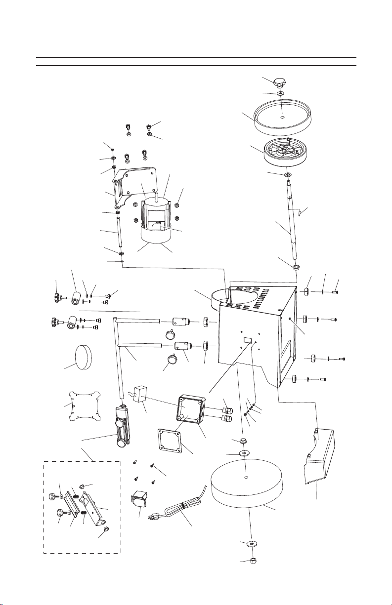
Main Breakdown
14
13
10
2
1
39-4
8
39
39-2
18
24
25
40
40
26
25
19
39-1
27
24
29
37-1
3
36
10
38
18
37
32
28
37-2
37-3
21
9
47
31-1
31
45
5
7
12V2
11
43
33
15
44
30
17
16
7
42
22
41
46
-26-
39-5
39-3
39-2
39-1
39-6
34
35
6
5
4
Model T10010 (Mfg. Since 3/10)
23
Page 29

REF PART # DESCRIPTION
1 PT10010001 ANGLE GUIDE
2 PT10010002 HONING PASTE
3 PT10010003 UNIVERSAL SUPPORT
4 PT10010004 HEX NUT M12-1.75
5 PT10010005 FLAT WASHER 12MM
6 PT10010006 GRINDING WHEEL
7 PT10010007 COLLAR BUSHING 15MM ID/17MM OD
8 PT10010008 HORIZONTAL SUPPORT HOLDER
9 PT10010009 VERTICAL SUPPORT HOLDER
10 PT10010010 KNOB BOLT M6-1 X 16
11 PT10010011 DRIVE WHEEL
12V2 PT10010012V2 STROPPING WHEEL V2.03.10
13 PT10010013 FLAT WASHER 8MM
14 PT10010014 KNOB NUT M8-1.25
15 PT10010015 FLAT WASHER 12MM
16 PT10010016 ROLL PIN 4 X 44
17 PT10010017 ARBOR SHAFT
18 PT10010018 FLAT WASHER 6MM
19 PT10010019 EXT TOOTH WASHER 6MM
21 PT10010021 GRINDER CASE
22 PT10010022 FOOT
23 PT10010023 WATER RESERVOIR
24 PT10010024 E-CLIP 8MM
25 PT10010025 FLAT WASHER 10MM
26 PT10010026 MOTOR BRACKET SHAFT
27 PT10010027 MOTOR BRACKET
28 PT10010028 HEX NUT M6-1
29 PT10010029 SPECIAL NUT
30 PT10010030 HEX NUT M4-.7
31 PT10010031 SWITCH HOUSING
31-1 PT10010031-1 SWITCH HOUSING GASKET
32 PT10010032 TAP SCREW M4 X 20
33 PT10010033 PHLP HD SCR M4-.7 X 10
34 PT10010034 SWITCH W/DISABLING KEY
35 PT10010035 POWER CORD
36 PT10010036 S CAPACITOR 10M 250V 1-3/16 X 1-5/8
37 PT10010037 MOTOR 1/4HP 110V 1650RPM
37-1 PT10010037-1 MOTOR FAN COVER
37-2 PT10010037-2 MOTOR FAN
37-3 PT10010037-3 MOTOR 1/4HP 120V 1-PH
38 PT10010038 TAP SCREW M4 X 10
39 PT10010039 GRINDING JIG
39-1 PT10010039-1 BUSHING
39-2 PT10010039-2 COMPRESSION SPRING
39-3 PT10010039-3 CLAMP PLATE
39-4 PT10010039-4 FLAT WASHER 6MM
39-5 PT10010039-5 KNOB M6-1 x 16
39-6 PT10010039-6 BASE PLATE
40 PT10010040 SHAFT BUSHING
41 PT10010041 PHLP HD SCR M6-1 X 12
42 PT10010042 FLAT WASHER 6MM
43 PT10010043 LOCK WASHER 4MM
44 PT10010044 EXT TOOTH WASHER 4MM
45 PT10010045 STRAIN RELIEF
46 PT10010046 FLANGE NUT M6-1
47 PT10010047 THIN HEX NUT M20-2.5
Model T10010 (Mfg. Since 3/10)
Main Parts List
-27-
Page 30

Machine Labels Breakdown & Parts List
101
105
102
103
104
-28-
REF PART # DESCRIPTION
101 PT10010101 ROTATION DIRECTION ARROW
102 PT10010102 MACHINE ID LABEL
103 PT10010103 RESPIRATOR LABEL VERT
104 PT10010104 READ MANUAL-VERTICAL NS 7/05
105 PT10010105 GRIZZLY GREEN TOUCH-UP PAINT
Model T10010 (Mfg. Since 3/10)
Page 31

WARRANTY CARD
Name _________________________________________________________________
Street _________________________________________________________________
City _______________________ State _________________________ Zip _________
Phone # ____________________ Email ________________________ Invoice # _____
Model # ____________________ Order # _______________________ Serial # ______
The following information is given on a voluntary basis. It will be used for marketing purposes to
help us develop better products and services. All information is strictly confidential.
1. How did you learn about us?
____Advertisement ____Friend ____Catalog
____Card Deck ____Website Other:________________________
2. Which of the following magazines do you subscribe to?
____ Cabinet Maker
____ Family Handyman
____ Hand Loader
____ Handy
____ Home Shop Machinist
____ Journal of Light Cont.
____ Live Steam
____ Model Airplane News
____ Modeltec
____ Old House Journal
3. What is your annual household income?
____$20,000-$29,000 ____$30,000-$39,000 ____$40,000-$49,000
____$50,000-$59,000 ____$60,000-$69,000 ____$70,000+
____ Popular Mechanics
____ Popular Science
____ Popular Woodworking
____ Practical Homeowner
____ Precision Shooter
____ Projects in Metal
____ RC Modeler
____ Rie
____ Shop Notes
____ Shotgun News
____ Today’s Homeowner
____ Wood
____ Wooden Boat
____ Woodshop News
____ Woodsmith
____ Woodwork
____ Woodworker West
____ Woodworker’s Journal
____ Other:
4. What is your age group?
____20-29 ____30-39 ____40-49
____50-59 ____60-69 ____70+
5. How long have you been a woodworker/metalworker?
____0-2 Years ____2-8 Years ____8-20 Years ____20+ Years
6. How many of your machines or tools are Grizzly?
____0-2 ____3-5 ____6-9 ____10+
7. Do you think your machine represents a good value? ____Yes ____No
8. Would you recommend Grizzly Industrial to a friend? ____Yes ____No
9. Would you allow us to use your name as a reference for our customers in your area?
Note: We never use names more than 3 times. ____Yes ____No
10. Comments: _________________________________________________________
______________________________________________________________________
______________________________________________________________________
______________________________________________________________________
Page 32

Send a Grizzly Catalog to a friend:
Name________________________________
Street________________________________
City______________State______Zip_______
FOLD ALONG DOTTED LINE
GRIZZLY INDUSTRIAL, INC.
P.O. BOX 2069
BELLINGHAM, WA 98227-2069
TAPE ALONG EDGES--PLEASE DO NOT STAPLE
Place
Stamp
Here
Page 33

WARRANTY
Grizzly Industrial, Inc. warrants every product it sells for a period of 1 year to the original
purchaser from the date of purchase. This warranty does not apply to defects due directly or
indirectly to misuse, abuse, negligence, accidents, repairs or alterations or lack of maintenance. This is Grizzly’s sole written warranty and any and all warranties that may be implied
by law, including any merchantability or fitness, for any particular purpose, are hereby limited
to the duration of this written warranty. We do not warrant or represent that the merchandise
complies with the provisions of any law or acts unless the manufacturer so warrants. In no
event shall Grizzly’s liability under this warranty exceed the purchase price paid for the product and any legal actions brought against Grizzly shall be tried in the State of Washington,
County of Whatcom.
We shall in no event be liable for death, injuries to persons or property or for incidental,
contingent, special, or consequential damages arising from the use of our products.
To take advantage of this warranty, contact us by mail or phone and give us all the details.
We will then issue you a “Return Authorization Number,” which must be clearly posted on
the outside as well as the inside of the carton. We will not accept any item back without this
number. Proof of purchase must accompany the merchandise.
The manufacturers reserve the right to change specifications at any time because they
constantly strive to achieve better quality equipment. We make every effort to ensure that
our products meet high quality and durability standards and we hope you never need to use
this warranty.
Please feel free to write or call us if you have any questions about the machine or the
manual.
Grizzly Industrial, Inc.
1203 Lycoming Mall Circle
Muncy, PA 17756
Phone: (570) 546-9663
Fax: (800) 438-5901
E-Mail:
techsupport@grizzly.com
Web Site: http://www.grizzly.com
Thank you again for your business and continued support. We hope to serve you again
soon!
Page 34

Buy Direct and Save with Grizzly®– Trusted, Proven and a Great Value!
~Since 1983~
ORDER
24 HOURS A DAY!
1-800-523-4777
Visit Our Website Today For
Current Specials!
 Loading...