

Page 1

Page 2

Content:
1. GEN.3 updates overview
2. General information
3. Functions over view
4. Technical parameters
5. PSJ installation
6. Fire modes and programming
7. Troubleshooting
8. Package contents
OEM version
Products with OEM indicate is determined for experts. T he lower price is compensated by absen c e of pa c kaging,
extensive manual and some universal accessories. If you are buying an OEM version we assume that you are
expert of AEG and in case of complain t will be detailed examined da m a ge by faulty installation.
1. GEN.3 news overview
• simplified unit installation
• simplified magnet installation – polarity doesn’t a ffect functionality
• lower energy con s umption, as low a s 3.9mA
• can be used with spring up to M200 with r a te of f ir e 99rpm
• longer wires, su itable for all replica types
• adjustable rate of fire
• adjustable active brake with possibility to be completely disabled
• compatible with batteries up to 4S / 16.8V
• a screw added to accessories to attach the unit into the gearbox
• new, thicker insulation foil preve nting short circu it
• possible usage of dual sector gears
• layered varnis h coating preventing short circuit
• new service connector
2. Basic information
New generation of PSJ processor unit brings m any new functions a nd easier installation. All the great f unction of
previous generations ar e kept - contactless magnetic switchin g, powerful MOSFET cooled via the whole gearbox,
active brake fully functional in any mode, programmable burst and so on.
On top of that the active brake is now adjustable up to completely disabled, we’ve added advan c ed r a te of fire
settings, energy cons umption is now as low as 3.9mA and ther e a r e man y more new features and updates.
Generation 3 un its are suitable for AE G replicas accordin g to the version of gearbox each unit is des ig ned for.
Units have been tested in gearbox es of following manufacturers*:
AimTop, APS, ARES, ASG Ultimate, Cyma, DBoys, Guarder, RetroArms, SHS, SRC
3. Functions overview
3.1. Fire modes
• 6 pre-set fire modes
• configurable burst mode - f r om 1 up to 255 BBs shot on one quick trigger pull, th is setting works in all
modes containing burst
• automatically s witches from bur s t to full auto when trigger pulled for longer time, without a ny delay
• modes are fully programma ble by the trigger (see figure 6.2.)
Page 3

3.2. Rate of fire
• allows you to set de la y between the two following shots
• allows smooth ra te of fire setting
• programmable by trigger (see figure 6.2.)
3.3. Special funct ions
• default settings reset: You can simply r es et a ll settings to their default values by trigger (see figure 6.2.)
• manual mode: If your PSJ indicates damage and you are sure it is not mechanical and your replica is able to
shoot, you can access manual mode in which malfunction is ignored. You can then fire on full auto mode
only (see figure 6.4).
• WARNING! By poor judgemen t, you can cause more damage to your replica a nd the unit!
3.4. MOS-FET
• no mechanical switch, switchin g is contactless
• faster trigger response
• increased rate of fire and batter y life
• maximum current up to 202A constant and 808A in peek
3.5. Active brake
• stops motor immediately with piston in default position and spring loos e (when 100% set)
• increases lifet im e of piston, sprin g a nd many other parts
• always finishes whole rotation of g ea r wheels
• fully function a l in all fire modes
• adjustable by steps of 10%
• possibility to completely disable a c tive brake (set 0%)
3.6. Malfunction detection
• unit detects mechanical damage and disables shooting to prevent any other damage
• user is warned by motor vibrati on s ( s ee figure 6.3.)
3.7. Li-Pol/Li-Ion/Li-Fe battery check
• when lithium ba ttery is discharged, unit warns user by motor vibrations (see figure 6.3.)
• battery type needs to be set – eas ily done using trigger itself ( s ee figure 6.2.)
• warning is off f or Ni-MH, Ni-Cd batteries
3.8. Realistic trigger operation
• trigger sensitivity can be set durin g installation to best fit your demands
3.9. Anti-reversal latch
• solves problem with double shot on se m i
• anti-reversal latch may not be needed if the mo tor is powerful enough (not recom mended)
3.10. All this hi dden inside your gearbox
• the whole unit is installed inside your gearbox, replac ing trigger contacts
• only two power wire s c ome from gearbox
• unit is equipped with LED indication of correct installation for easier installation
4. Technical parameters
• Top quality silicone wiring. 1mm
• Powerful MOS FE T with maximum curr e nt up to 202A constant and 808A in peak allows use almost without
any restrictions .
• MOSFET is effectively cool ed by the whole gearbox.
• The whole unit is coated in multiple layers of varnis h for maximum durability even in poor conditions.
• Replica‘s rate of fire is limited by gea r b ox components a nd technical spec ifications. PSJ unit itself is able to
do up to 500 000 cycles (shots) per s ec on d. Unit is tested for 99 cycles (shots) per second.
• Current consu m ption of unit in standby mode is as low as 3.9mA.
2
in cut capable of tra nsmitting up to 47A con stant.
Page 4
5. PSJ-VZ58 installation
! PSJ-VZ58 gen.2 should be installed by specialists only !
Advanced knowle dge of AEG replic a s is. Also basics in electronics and soldering skills a r e needed.
Never use soldering gun! Manufact ur e r ta k e s no responsibi lity for damaged caus ed by unprofessional
installation!
5.1. Preparation of PSJ for install a t ion
Pict.1: Self-con tained unit – OEM version
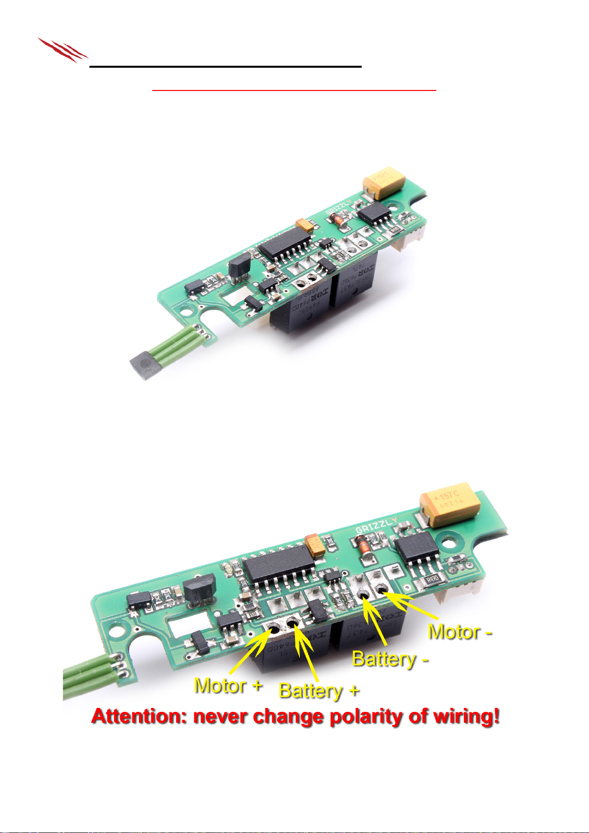
5.2. Soldering of wiring diagram
Wiring diagram of s e lf-contained processor unit. During the s oldering wires be extremely caref ul. If you change
polarity you ca n destroy unit after connecting to powe r source.
Pict.2: Wiring diag r a m pro unit with OEM version
Page 5

5.3. Recommended soldering wiring
Pict.3: Example of soldering for OEM version.
5.4. Preparation
For PSJ-VZ58 installation take gearbox out of your replica and remove or iginal processor u nit. To remove the u nit
must be removed also the selector plate.
Pict.4: Removed gearbox from the replica without original pr oc e s sor unit
Page 6

5.5. Heat-conductive f oil
On both transistors stick enclosed h eat-conducting foils. Foils are self-adhesive, is necessary to remove protectiv e
foil from them - from both s ide s .
Pict. 5: Removing the protective foi ls from the heat-condu c tin g foils and their placing, gearbox check
5.6. PSJ-VZ58 installation
Insert your unit to original position on gearbox. If unit doesn’t fit on gearbox you can adjust it by rasping. After
your unit is placed you must check f or an y c onductive contacts with gearbox. I f there are some conductive
contacts you h a ve to remove them, f or example by rasping the unit or your gearbox , or you can use an insulating
material. Bottom side of unit is insulated by pre-installed insulation foil.
Pict. 6: Installing new processor unit on gea r box
Page 7

5.7. Fixation of new pr ocessor unit
Fix new process or unit by original scr e ws. Make last chec k if everything fits how it should be before full screws
tighten.
Pict. 7: Fixed new processor unit
5.8. Checking the cut-of l ever
After you corre c tly install the processor unit check if magnet is inserted in gea r wheels and is directly over the
probe. Everything was tes ted on m ore guns but may happen that the ARES manufacturer changes gearbox or
dimensions of plate without notice. This situation will be necessary to deal with the GRIZZLY manufacturer.
Pict. 8: Check ing the settings of ma gnets for „cut-of lever“ and hall probe
Page 8

5.9. Inserting the se lector plate
After correct installation of new processor unit reinsert the s ele c tor plate to its original position. Check if magnet is
directly over th e hall probe when selec tor plate is in position „auto“. Ev er ything was tested on m or e g uns but may
happen that that the ARES manufacturer changes gearbox or dim ensions of plate w ithout notice. T his situation will
be necessary to deal with the GRIZZLY manufacturer.
Pict. 9: Check ing the settings of selector plate’s mag net with the probe ha ll
5.10.1 Magnet installation on the trigger
Set the trigger to p os ition, where you want your replica to fire. Put the magnet on trigger as close as possible to
the sensor. If you want sensitive trigger pu t the magnet as c loses t to th e probe when your trigger isn’t pressed
(just before the LEDs light up). LED has never lights in the basic position.
Now stick the magnet. Magnet’s polari ty doesn’t matter.
If needed, you can very gently bend the probe to be very close to magnet when you press trigger, but not to
touch it.
Pict.10: Insta lla tion magnet onto the tr igger
Page 9

5.10.2 Magnet installation on the trigger
The checking is very simple: LED must flash when you push the trigger
Exact notifica tion of trigger:
Free trigger - LED doesn ’t light
Pushed trigger (firing) - LED lights
Pict. 11: Notifications of the trigger by using LED
5.11. Replica completion
Assemble the rest of your gearbox in standard way and insert it in your replic a . You can now test
your PSJ-M3 and set your prefered fire modes.
WARNING: Be careful on wires whe n you put the gearbox into the body of your rep lic a.
Page 10

6. Fire modes and programming
Selector on semi:
Selector on auto:
1.
Semi
Burst / Auto
2.
Semi
Auto
3.
Semi
Semi
4.
Semi
Burst only
5.
Burst only
Auto
6.
Burst only
Burst / Auto
Category
(selection is con firmed by moto
vibrations, number of vibrati
= number of menu selected)
Values
1) Burst setting
Number of trigger pulls = number of s hots in burst
2) Battery check setting
1) Li-Pol, Li-Ion (default)
2) Li-Fe
3) Off (recommended for Ni-MH, Ni-CD)
3) Fire mode setting
1) Semi - Burst/Auto (default)
2) Semi - Auto
3) Semi - Semi
4) Semi - Burst only
5) Burst only - Auto
6) Burst only - Burst/Auto
of currently s ele c ted of fire mode is)
4) Shooting delay set tin g
Each trigger pull = +20ms
0ms, for default value, just hold the trigger pulled for 5s )
5) Reset to defau lt values
(returns all settings to their
default values)
Hold the trigger pu lled for 5s to confirm r e s ta rt. If you do not wish to reset your
6) Rate of fire settin g
Each trigger pull = - 10% (range 100% - 10%)
value, just hold the trigger pulled f or 5s)
7) Active brake setting
Each trigger pull = - 10% (range 100% - 0%)
for default value, just hold the trig ge r pulled for 5s)
6.1. Preset modes
6.2. Unit programming
a) For programming, connect a battery and within 5 seconds pull and hold the tr igger for another 5 seconds.
Entering is confirmed by the motor vib r a ting twice.
b) Next, choose cate gory from menu by pulling the trigger as ma ny times as the category number you w ish to
select indicates. To confirm selecti on, pull and hold th e tr igger for 5 seconds . Your choice is confirmed by
motor vibrating as many times as th e s e lec ted number is and you are now in the su bm enu.
c) When changing fire mode (submen u 3), every trigger pull is followed by m otor vibrating as many time s a s
the number of cur rently selected fire mode indicates. Submenu goes in circle, so number 6 is followed by
number 1. For submenu values, refer to the table below.
d) When you are don e with setting value, pull and hold the trig ge r for 5 seconds to sa ve your settings. Double
vibration confirms successful s a ving and exiting programming fun c tion. Now you’re ready to go. Your
settings stay saved even after disconnecting the battery.
r
(after you selec t value, confirm it by holding the trigger pulled f or 5s)
ons
(default = 3 shots)
(every trigger pull is followed by motor vibrating as ma ny times as the number
(every time you s e t the delay, you sta r t from the default value
settings, disconnect your battery.
(every time you s e t the rate, you start from the default value 100%, for defau lt
(every time you set the brak in g effect, you start from the defa ult value 100%,
Example of programming:
Then pull the trigger 3 times and then pull and hold for 5s – you‘re entering Fire mode setting. Entering is co nf irmed by three
vibrations. Now pull the trigger - after each pull , v ibr ations will tell you which mode you‘re on. If you pulled the trigger 5 times,
you chose number 5 (mode Burst only - Auto). Five vibrations w il l confirm this selection. To save it, pull and hold the trigger for
5s. Now double vibration sounds, which means the setting is saved and the programming mode has been shut. Your replica is
now ready with selected setting.
First, connect the battery and pull and hold the trig ge r for 5 seconds. Double vibration will sound.
Page 11

6.3. Motor vibrations meaning (outside programming mode)
• 1x vibration - after th e ba tter y has been connected, unit perf orm s a s elf-check and confirms functionality
• 2x vibration - entering programming mode, savin g a nd exiting programming mode
• 3x vibration - malfunction or damage detected
• 4x vibration - low ba tte r y detec ted
• 6x vibration - entering manual mode
6.4. Manual mode
If your PSJ indicates damage and you are sure it is not mechanical malfunction and you r replica is able to shoot,
you can access manual mode. In this mode, malfunction is ignored and you are allow ed to fire on full au to m od e,
regardless of selected fire m ode or s elector setting.
WARNING! By poor judgement, you can cause more damage to your r e plica and PSJ unit!! T his mode is not
recommended for users without advanced knowledge of A EG replicas principles!
To enter manua l m ode a fter your replica indicates malfu nction, just pull a nd hold the trigger for 10 s e c onds.
Entering is confirmed by 6 vibrations.
7. Troubleshooting
Is your PSJ not working correctly ? Check, where the problem could be:
7.1. Replica is not reacting at all.
• Check if the battery is conn ec ted a nd charged properly. Also check that all wires are connected properly to
all elements – motor , battery.
• If the replica is equipped with safety fuse, check if the fuse hasn’t been blown.
7.2. Replica vibrates when battery is connected, but after that it does not rea c t .
• Problem in trigger s etting. Chec k if your trigger is ins talled properly – ma g net should almost touch the
sensor when the trigger is pu lled. Adjust if needed.
7.3. Selector is set on “semi”, but acts like “auto” is selected.
• Poor selector pla te installation. Check, whether the magnet on the selector is directly abov e the sensor when
selector is set on semi. Adjust if needed.
7.4. Selector is set on “auto”, but acts like “semi” is selected.
• Poor selector pla te installation. Check, whether the magnet on the selector is away from sensor when
selector is set on auto. Adjus t if needed.
• Check if the fire selector is properly moving the selector plate when switched.
• Check if the selector plate is run ning smoothly in the gearb ox. I fit gets jammed, adjust the selector plate or
the gearbox to allow s mooth movement.
7.5. Replica s hoots one or more shots and then vibrates 3 times.
• Cut-off lever not working properly. Check if the magnet is close enough to the sensor, L ED indication will
help you. Adjust if necess ary .
• Check if the selector plate spring is s tr ong enough to retur n the cut-off lev er to its base position. If not, the
magnet might be too far from th e s ensor. The cut-off lever needs to return to its ba se position in all fir e
modes. Using stronger spring is recommended.
• Check if the cut-off lever is installed properly. Im p r ope r installation can r e s ult in lateral movem e nt of cut-off
lever during sh ooting, pushing it ou t of range of the sens or .
7.6. Replica does not shoot, just vi br a t e s 3 times and the vibra tes with each trigger pu ll.
• Mechanical ma lfunction of your r ep lic a has been detected . Check if the m otor a nd the gears are n ot jammed
and are working properly. If you are sure the replica is mechanically ok, you can access manual mode – see
figure 6.4.
• Check if the selector plate is not lifting up the cut-off lever a nd preventing the cycle to be finished. If so, it‘s
necessary to en la rge the area cut off of the selector plate in or der not to lift the c ut-off lever.
7.7. Replica vibrates 4 times repeatedly.
• Your battery is discharged. Change your battery an d do not for get to charge the discharged on e.
• If your battery is charged proper ly, your battery setting ma y be wrong – see figure 6.2 to adjust th e s ett ing.
7.8. If your installation is unsuc c e ssful.
• If your installation is unsuccessful, you can opt to send your r e plica to our installation and repair center.
Please notify u s by email to shop@grizzlyairsoft.com
Address to ship your replica to: Grizzly Airsoft, Zizkova 84/7, 682 01 Vy s k ov, Czech Republic
Page 12

8. Package content
• processor unit PSJ gen.3
• pre-installed insula tion foil
• heat conductin g foil
• magnets
WARNING: PSJ shou ld b e installed by qualified AEG profes sionals only! Manufacturer is not lia ble for any
damage on the replica caused by unpr ofessional installation. Do not use sold ering gun!
 Loading...