

Page 1

Page 2

Content:
1. GEN.3 updates overview
2. General information
3. Functions over view
4. Technical parameters
5. PSJ installation
6. Fire modes and programming
7. Troubleshooting
8. Package contents
1. GEN.3 news overview
• simplified unit installation
• simplified magnet installation – polarity doesn’t a ffect functionality
• lower energy con s umption, as low a s 3.9mA
• can be used with spring up to M200 with r a te of f ir e 99rpm
• longer wires, su itable for all replica types
• adjustable rate of fire
• adjustable active brake with possib ility to be complet ely disabled
• compatible with batteries up to 4S / 16.8V
• a screw added to accessories to attach the unit into the gearbox
• new, thicker insulation foil preve nting short circu it
• possible usage of dual sector gears
• layered varnis h coating preventing short circuit
• new service connector
2. Basic information
New generation of PSJ proc es sor unit brings ma ny new functions and easier installation. All the great function of
previous generations ar e kept - contactless magnetic switchin g, powerful MOSFET cooled via the whole gearbox,
active brake fully functional in any mode, programmable burst a nd so on.
On top of that the active brake is now adjustable up to completely disabled, we’ve added advan c ed r a te of fire
settings, energy cons umption is now as low as 3.9mA and ther e a r e man y more new features and updates.
Generation 3 un its are suitable for AE G replicas accordin g to the version of gearbox each unit is des ig ned for.
Units have been tested in gearbox es of following manufacturers*:
AimTop, APS, ARES, ASG Ultimate, Cyma, DBoys, Guarder, RetroArms, SHS, SRC
*Every manufacturer inno vat es their products over the time, so there is po ssi bil ity, that the gearbox tested by us is different from yours. However
this only means, that your installation might require some minor adjustments.
3. Functions overview
3.1. Fire modes
• 6 pre-set fire modes
• configurable burst mode - f r om 1 up to 255 BBs shot on one quick trigger pull, th is setting works in all
modes containing burst
• automatically s witches from bur s t to full auto when trigger pulled for longer time, without any delay
• modes are fully programm a ble by the trigger (see figure 6.2.)
3.2. Rate of fire
• allows you to set de la y between the two following shots
• allows smooth ra te of fire setting
• programmable by trigger (see figure 6.2.)
3.3. Special funct ions
• default settings reset: You can simply reset all settings to their default values by tr igger ( s ee figure 6.2.)
• manual mode: If your PSJ indicates damage and you are sure it is not mechanical and your replica is able to
shoot, you can access manual mode in which malfunction is ignored. You can then fire on full auto mode
only (see figure 6.4).
• WARNING! By poor judgemen t, you can cause more damage to your replica a nd the unit!
Page 3

3.4. MOS-FET
• no mechanical switch, switchin g is contactless
• faster trigger response
• increased rate of fire and batter y life
• maximum current up to 202A constant and 808A in peek
3.5. Active brake
• stops motor immediately with piston in default position and spring loos e (when 100% set)
• increases lifet im e of piston, sprin g a nd many other parts
• always finishes whole rotation of g ea r wheels
• fully function a l in all fire modes
• adjustable by steps of 10%
• possibility to completely disable a c tive brake (set 0%)
3.6. Malfunction detection
• unit detects mechanical damage and disables shooting to prevent any other damage
• user is warned by motor vibrati on s ( s ee figure 6.3.)
3.7. Li-Pol/Li-Ion/Li-Fe battery check
• when lithium ba ttery is discharged, unit warns user by motor vibrations (see figure 6.3.)
• battery type needs to be set – eas ily done using trigger itself (see figure 6.2.)
• warning is off f or Ni-MH, Ni-Cd batteries
3.8. Realistic trigger operation
• trigger sensitivity can be set durin g installation to best fit your demands
3.9. Anti-reversal latch
• solves problem with double shot on se m i
• anti-reversal latch may not be needed if the mo tor is powerful enough (not recom mended)
3.10. All this hi dden inside your gearbox
• the whole unit is installed inside your gearbox, replac ing trigger contacts
• only two power wire s c ome from gearbox
• unit is equipped with LED indication of correct installation for easier installation
4. Technical parameters
• Top quality silicone wiring. 1mm
• Powerful MOS FE T with maximum curr e nt up to 202A constant and 808A in peak allows use almost without
any restrictions .
• MOSFET is effectively cool ed by the whole gearbox.
• The whole unit is coated in multiple layers of varnis h for maximum durability even in poor conditions.
• Replica‘s rate of fire is limited by gearbox components and technical s pe c ifications. PSJ unit itself is able to
do up to 500 000 cycles (shots) per s ec on d. Unit is tested for 99 cycles (shots) per second.
• Current consu m ption of unit in standby mode is as low as 3.9mA.
2
in cut capable of tra nsmitting up to 47A con stant.
Page 4
5. PSJ-M3 installation
! PSJ should be installed by specia lists only!
Advanced knowle dge of AEG replic a s is crucial!
Basic knowledge of electronics and s oldering skil ls are needed as well .
Never use soldering gun!
Manufacturer takes no responsi bility for damages c a used by unprofessiona l installati on!
5.1. Preparation
For PSJ-M3 installation, take ge a r b ox out of your replica, open it and remov e all of its content.
Pict.1: Gearbox with all of its content removed
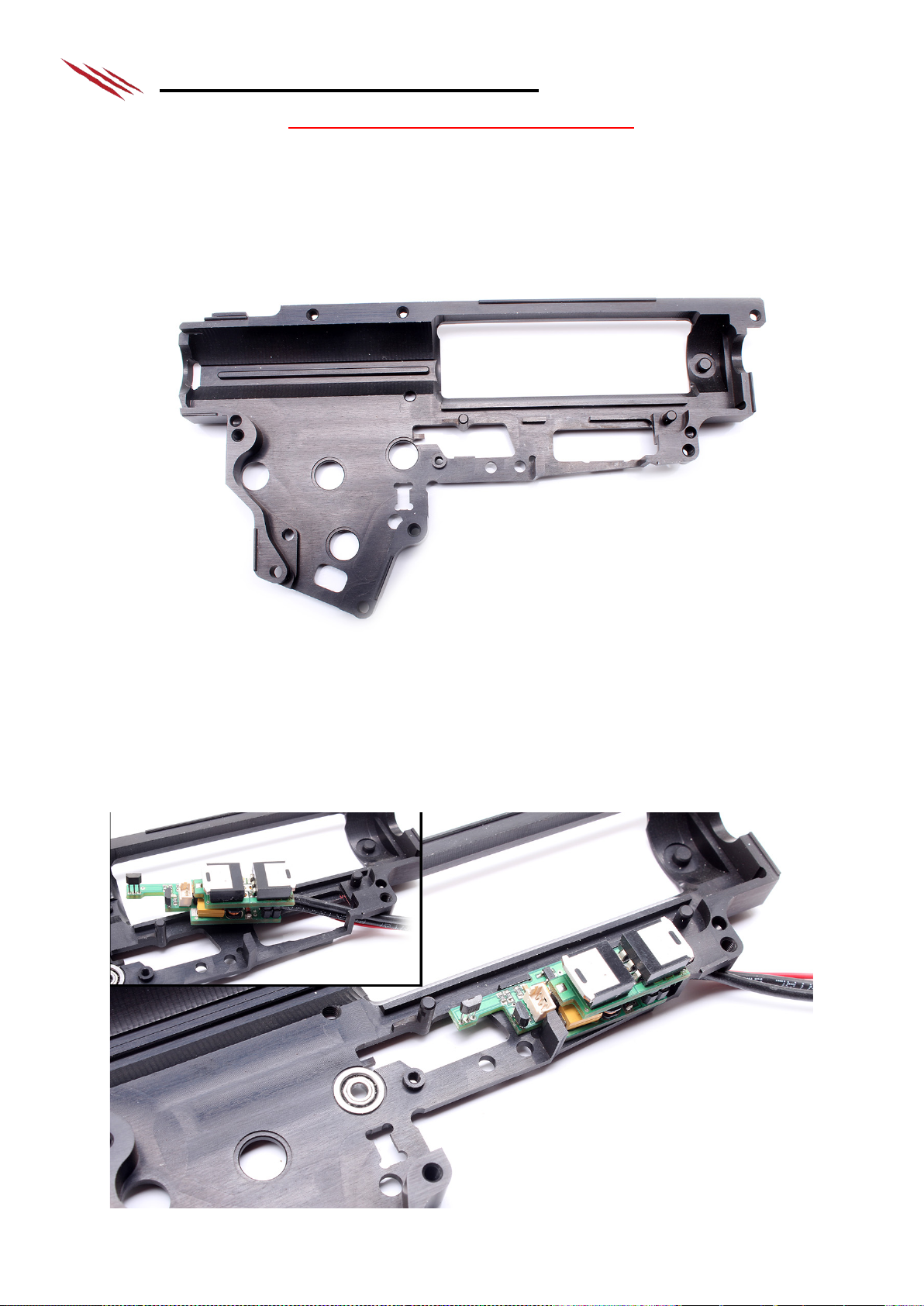
5.2. PSJ-M3 mounting
Insert your unit into gearbox, bottom side first. If it does not fit properly, you need to adjust gear box. Prepare
gearbox for smoo th unit insertion. After your unit is place d, check for any c onductive contacts with g ea rbox. If
there are any, you need to insulate th em ! You can sharpen your gearbox or you ca n use some insulation m a te r ial.
Bottom side of un it is insulated by pre-installed insul ation foil. Before final insertion, r em ove protective f oil from
heat-conducting foil. Now you can fix the unit with a screw and organise cables. Never sharpen the unit.
Pict.2: Insta lled P SJ-M3 gen.2
Page 5

5.3. Selector plate
Insert prepared selector pl a te in to position of your g earbox. Check if the magnet is right above the probe, when
selector is set on se m i. If not, adjust magnet on selector plate. If you wish to m od ify your own se lector plate, you
need to remove part of plate where it meets cut-off lever. Finally, stick the m agnet on selector, so it is a b ove the
probe when selector is s et on semi. Magnet polari ty does n’t matter, magnet must be ov er the probe when is set
on semi. For better placing, we r e c om mend to mill a slot for the magnet.
Pict.3: Selector plate in position a nd its adjustments
Pict.4: Representation of sensor for selector plate
Page 6

Pict.5: Position of selector pla te in set on semi
5.4. Cut-off lever installation
Place the magnet on your cut-off lever, s o in its default position, m agnet almost touches the probe. It is enough to
use superglue. For correct installation, there is LED indicator on the unit. For control of right position of mag net,
connect your battery to laboratory pow er s upply and insert the piston gear. By rotat ing it, cut-off leve r s hould lift
and return and LED indicator should r e a c t b y turning off an d on again. If you incorre c t c onnect power source and it
will cause a short-circuit, it will lead to irrefutable damage of your PSJ.
Test example: connect battery power source to power wires +(red) and –(black), LED indicator will light up for 5s (will make unit
check), then is possible to rotate pisto n gear and test cut-off le ver function. LED indicator will turn on and off when magnet will
be closer or farther from probe.
Importatnt warning: if you press trigger with alre ady ins talle d magnet, you will deactivate test mode and LED indicator will not
react on cut-off lever move. For test mode reactivation you need to disconnect a connect again power source.
Pict.6: Insertion of selector plate including magn e t
Page 7

Pict.7: Movement of cut-off lever, LED indication of right mag net‘s installation
5.5. Trigger prepartion
Insert trigger into your gearbox a nd check if it goes smooth ly. If not, adj ust your trigger. Set the trigger to
position, wher e you want your replica to fire and mark the c e nter of the probe. Now stick the magnet onto the
trigger. If needed, you can very gently bend the probe to be ver y close to magnet, but not to touch it.
Pict.8: Right position of magnet for trigger
Page 8

Obr.9: Sample of ideal trigger’s switching
5.6. Placing heat-conductive foi l
Remove protective foils from both s id es of heat-condu c tive foil. Place one on each transistor . After that, close y our
gearbox and check, if it can be closed without any problem. If not, adjust gearbox.
Pict.10: Removing protectiv e foils from heat-conductiv e foils and their placing
Page 9

5.7. Check of unit connection
Before final testing don’t forget to conncet supply wire to power red wire. I f you don’t do it and you will be test
your unit, it can le a d to ir refutable damage of your P SJ!
Pict.11: Check of unit connection
5.8. Replica complet ion
Assemble the rest of your gearbox in standard way and insert it into your replica. You can now tes t your PSJ-M3
and set your prefered fire mode.
Page 10

6. Fire modes and programming
Selector on semi:
Selector on auto:
1.
Semi
Burst / Auto
2.
Semi
Auto
3.
Semi
Semi
4.
Semi
Burst only
5.
Burst only
Auto
6.
Burst only
Burst / Auto
Category
number of menu selected)
Values
(after you selec t value, confirm it by holdin
the trigger pulled f
1) Burst setting
Number of trigger pulls = number of s hots in burst
(default = 3 shots)
2) Battery check setting
1) Li-Pol, Li-Ion (default)
2) Li-Fe
3) Off (recommended for Ni-MH, Ni-CD)
3) Fire mode setting
1) Semi - Burst/Auto (default)
2) Semi - Auto
3) Semi - Semi
4) Semi - Burst only
5) Burst only - Auto
6) Burst only - Burst/Auto
(every trigger pull is followed by motor vibrating as ma ny times as the number of
currently selected of fire mode is)
4) Shooting delay setting
Each trigger pull = +20ms
(every time you s e t the delay, you sta r t from the default value
0ms, for default value, just hold the trigger pulled for 5s )
5) Reset to defau lt values
(returns all settings to their default
values)
Hold the trigger pu lled for 5s to confirm r e s ta rt. If you do not wis h to reset your
settings, disconnect your battery
6) Rate of fire setting
Each trigger pull = - 10% (range 100% - 10%)
(every time you s e t the rate, you start from the default value 100%, for defau lt
value, just hold the trigger pulled f or 5s)
7) Active brake setting
Each trigger pull = - 10% (range 100% - 0%)
(every time you set the brak in g effect, you start from the defa ult value 100%,
for default value, just hold the trig ge r pulled for 5s)
6.1. Preset modes
6.2. Unit programming
a) For programming, connect a battery and within 5 seconds pull and hold the trigger for another 5 secon d s .
Entering is confirmed by the motor vib r a ting twice.
b) Next, choose category from menu by pulling the trigger as many times as the category number you wish to
select indicates. To confirm selecti on, pull and hold th e tr igger for 5 seconds . Your choice is confirmed by
motor vibrating as many times as th e s e lec ted number is and you are now in the su bm enu.
c) When changing fire mode (s ubmenu 3), every trigger pull is followed by motor vibrating as m a ny times as
the number of cur rently selected fire mode indicates. Submenu goes in circle, so number 6 is followed by
number 1. For submenu values, refer to the table below.
d) When you are done with setting value, pull and hold the trigger for 5 seconds to sa ve your settings. Double
vibration confirms successful s a ving and exiting programming fun c tion. Now you’re ready to go. Your
settings stay saved even after disconnecting the battery.
(selection is con firmed by motor
vibrations, number of vibrations =
g
or 5s)
.
Example of programming:
Then pull the trigger 3 times and then pull and hold for 5s – you‘re entering Fire mode setting. Ente ring is confirmed by three
vibrations. Now pull the trigger - after each pull, vibrations will tell you which mode you‘re on. If you pulled the trigger 5 times,
you chose number 5 (mode Burst only - Auto). Five vibrations will confirm this selection. To save it, pull and hold the trigger for
5s. Now double vibration sounds, which means the setting is saved and the programming mode has been shut. Your replica is
now ready with selected setting.
First, connect the battery and pull and hold the trig ge r for 5 seconds. Double vibration will sound.
Page 11

6.3. Motor vibrations meaning
• 1x vibration - after th e ba tter y has been connected, unit perf orm s a s elf-check and confirms functionality
• 2x vibration - entering programming mode, savin g a nd exiting programming mode
• 3x vibration - malf unction or damage detected
• 4x vibration - low battery detec ted
• 6x vibration - entering manual mode
6.4. Manual mode
If your PSJ indic a te s d a m age and you are sur e it is not m echanical malfunction and your replica is able to shoot,
you can access manual mode. In this mode, malfunction is ignored and you are allow ed to fire on full au to m od e,
regardless of selected fire m ode or s elector setting.
WARNING! By poor judgement, you c an cause more damage to your replica and PS J unit!! This mode is not
recommended for users without advanced knowledge of A EG replicas principles!
To enter manua l m ode a fter your replica indicates malfu nction, just pull a nd hold the trigger for 10 s e c onds.
Entering is confirmed by 6 vibration s .
7. Troubleshooting
Is your PSJ not working correctly? Check, where the probl em could be:
7.1. Replica is not reacting at all.
• Check if the battery is conn ec ted a nd charged properly. Also check that all wires are connected properly to
all elements – motor , battery.
• If the replica is equipped with safety fuse, check if the fuse hasn’t been blown.
7.2. Replica vibrates when battery is connected, but a fter that it does not re a c t .
• Problem in trigger s etting. Chec k if your trigger is ins talled properly – ma g net should almost touch the
sensor when the trigger is pulled. Adjust if needed.
7.3. Selector is set on “semi”, but acts like “auto” is selected.
• Poor selector pla te installation. Check, whether the magnet on the selector is directly abov e the sensor when
selector is set on semi. Adjust if needed.
7.4. Selector is set on “auto”, but acts like “semi” is selecte d.
• Poor selector pla te installation. Check, whether the magnet on the selector is away from sensor when
selector is set on auto. Adjus t if needed.
• Check if the fire s e lec tor is properly moving the selector pla te when switched.
• Check if the selector plate is run ning smoothly in the gearb ox. I fit gets jammed, adjust the selector plate or
the gearbox to allow s mooth movement.
7.5. Replica s hoots one or more shots a nd th e n vibrates 3 ti mes.
• Cut-off lever not working properly. Check if the magnet is close enough to the sensor, L ED indication will
help you. Adjust if necess ary .
• Check if the selector plate spring is s tr ong enough to retur n the cut-off lever to its base position. If not, the
magnet might be too far from th e s ensor. The cut-off lever needs to return to its ba se position in all fir e
modes. Using stronger spring is recommended.
• Check if the cut-off lever is installed properly. Im pr op er installation can result in lateral movement of cut-off
lever during sh ooting, pushing it ou t of range of the sens or .
7.6. Replica does not shoot, just vibrates 3 times and the vibrates with each trigger pull.
• Mechanical ma lfunction of your r ep lic a has been detected. Check if the motor and th e gea r s a r e not jammed
and are working properly. If you are sure the replica is mechanically ok, you can access manual mode – see
figure 6.4.
• Check if the selector plate is not lifting up the cut-off lever a nd preventing the cycle to be f inished. If so, it‘ s
necessary to en la rge the area cut off of the selector plate in or der not to lift the c ut-off lever.
7.7. Replica vibrates 4 times repeatedly.
• Your battery is disc harged. Chan g e your battery and do n ot forget to charge th e discharged one.
• If your battery is charged proper ly, your battery setting ma y be wrong – see figure 6.2 to adjust th e s ett ing.
7.8. If your installation is unsuc c essful.
• If your installa tion is unsuccessful, you can opt to send your replica to our installation and r epa ir c enter.
Please notify u s by email to shop@grizzlyairsoft.com
Address to ship your replica to: Grizzly Airsoft, Zizkova 84/7, 682 01 Vyskov, Czech Republic
Page 12

8. Package content
• processor unit PSJ gen.3
• complete silicone wiring of your choice
• pre-installed insula tion foil
• heat conductin g foil
• magnets
• modified selector plate with magn e t installed
• dean-T plug – male
• gold-plated motor plugs – 2pcs
• gold-plated fuse plugs – 2pcs
• fuse mini
• heat shrink tubing
• user and installation manual
WARNING: PSJ should be installed by qualified AEG profes s ionals only! Manufacturer is not liable for any
damage on the replica caused by unpr ofessional installation. Do not use sold ering gun!
 Loading...