

Page 1
MODEL G0462
WOOD LATHE w/DIGITAL READOUT
OWNER'S MANUAL
(For models manufactured since 11/14)
COPYRIGHT © APRIL, 2010 BY GRIZZLY INDUSTRIAL, INC. REVISED AUGUST, 2015 (ST)
WARNING: NO PORTION OF THIS MANUAL MAY BE REPRODUCED IN ANY SHAPE
OR FORM WITHOUT THE WRITTEN APPROVAL OF GRIZZLY INDUSTRIAL, INC.
FOR MODELS MANUFACTURED SINCE 11/14 #TS12792 PRINTED IN CHINA
Page 2

This manual provides critical safety instructions on the proper setup,
operation, maintenance, and service of this machine/tool. Save this
document, refer to it often, and use it to instruct other operators.
Failure to read, understand and follow the instructions in this manual
may result in fire or serious personal injury—including amputation,
electrocution, or death.
The owner of this machine/tool is solely responsible for its safe use.
This responsibility includes but is not limited to proper installation in
a safe environment, personnel training and usage authorization,
proper inspection and maintenance, manual availability and comprehension, application of safety devices, cutting/sanding/grinding tool
integrity, and the usage of personal protective equipment.
The manufacturer will not be held liable for injury or property damage
from negligence, improper training, machine modifications or misuse.
Some dust created by power sanding, sawing, grinding, drilling, and
other construction activities contains chemicals known to the State
of California to cause cancer, birth defects or other reproductive
harm. Some examples of these chemicals are:
• Lead from lead-based paints.
• Crystalline silica from bricks, cement and other masonry products.
• Arsenic and chromium from chemically-treated lumber.
Your risk from these exposures varies, depending on how often you
do this type of work. To reduce your exposure to these chemicals:
Work in a well ventilated area, and work with approved safety equipment, such as those dust masks that are specially designed to filter
out microscopic particles.
Page 3

Table of Contents
INTRODUCTION ............................................... 2
Machine Description ...................................... 2
Contact Info.................................................... 2
Manual Accuracy ........................................... 2
Identification ................................................... 3
Machine Data Sheet ...................................... 4
SECTION 1: SAFETY ....................................... 6
Safety Instructions for Machinery .................. 6
Additional Safety for Wood Lathes ................ 8
SECTION 2: POWER SUPPLY ........................ 9
Availability ...................................................................9
Full-Load Current Rating ............................................. 9
110V Circuit Requirements .........................................9
Grounding & Plug Requirements ..............................10
Extension Cords ........................................................10
SECTION 3: SETUP ....................................... 11
Unpacking .................................................... 11
Needed for Setup ......................................... 11
Inventory ...................................................... 11
Cleanup ........................................................ 13
Site Considerations ...................................... 14
Anchoring to Floor ....................................... 15
Anchoring to Concrete Floors ...................................15
Assembly ..................................................... 15
Test Run ...................................................... 16
SECTION 5: ACCESSORIES ......................... 31
SECTION 6: MAINTENANCE ......................... 33
Schedule ...................................................... 33
Cleaning ....................................................... 33
Lathe Bed..................................................... 33
Tailstock ....................................................... 33
Lubrication ................................................... 33
Motor Shaft Lubrication .............................................34
SECTION 7: SERVICE ................................... 35
Troubleshooting ........................................... 35
Motor & Electrical ......................................................35
Aligning Centers........................................... 37
Replacing V-Belt .......................................... 37
SECTION 8: WIRING ...................................... 38
Wiring Safety Instructions ............................ 38
Electrical Components & Wiring Diagram ... 39
SECTION 9: PARTS ....................................... 40
Main ............................................................. 40
Machine Labels ............................................ 42
WARRANTY AND RETURNS ........................ 45
SECTION 4: OPERATIONS ........................... 18
Operation Overview ..................................... 18
Stock Inspection & Requirements................ 19
Adjusting Head............................................. 19
Adjusting Tailstock Position ......................... 20
Adjusting Tool Rest ...................................... 21
Installing/Removing Spur Center ................. 22
Installing Spur Center ................................................22
Removing Spur Center ..............................................22
Installing/Removing Live Center .................. 23
Installing Live Center .................................................23
Removing Live Center ...............................................23
Installing/Removing Faceplate ..................... 24
Adjusting Spindle Speed .............................. 25
Selecting Turning Tools ............................... 26
Spindle Turning ............................................ 27
Spindle Turning Tips .................................................28
Faceplate Turning ........................................ 29
Attaching Faceplate to Spindle .................................29
Using a Backing Block ..............................................29
Outboard Turning ......................................... 30
Sanding/Finishing Using the Lathe .............. 30
Page 4

INTRODUCTION
We are proud to provide a high-quality owner’s
manual with your new machine!
We
instructions, specifications, drawings, and photographs
in this manual. Sometimes we make mistakes, but
our policy of continuous improvement also means
that
you receive is
slightly different than shown in the manual
If you find this to be the case, and the difference
between the manual and machine leaves you
confused or unsure about something
check our
website for an updated version. W
current
manuals and
on our web-
site at
Alternatively, you can call our Technical Support
for help. Before calling, make sure you write down
the
from
the machine ID label (see below). This information
is required for us to provide proper tech support,
and it helps us determine if updated documentation is available for your machine.
We stand behind our machines. If you have
any questions or need help, use the information
below to contact us. Before contacting, please get
the serial number and manufacture date of your
machine. This will help us help you faster.
We want your feedback on this manual. What did
you like about it? Where could it be improved?
Please take a few minutes to give us feedback.
Machine Description
The Model G0462 Wood Lathe is designed to turn
wood stock so the operator can remove material
with a hand-held cutting tool or chisel.
The variable speed allows for infinite spindle
speed adjustment from 600–2400 RPM, and the
digital readout provides a precise reading of the
current spindle speed.
The ability to rotate and move the head allows for
turning workpieces with diameters larger than 12"
on the outboard side of the lathe.
The heavy-duty tailstock provides substantial
stability when mounting the workpiece between
centers.
Contact Info
Manual Accuracy
made every effort to be exact with the
sometimes the machine
.
,
e post
manual updates for free
www.grizzly.com.
Manufacture Date and Serial Number
Grizzly Technical Support
1203 Lycoming Mall Circle
Muncy, PA 17756
Phone: (570) 546-9663
Email: techsupport@grizzly.com
Grizzly Documentation Manager
P.O. Box 2069
Bellingham, WA 98227-2069
Email: manuals@grizzly.com
Manufacture Date
Serial Number
-2-
G0462 Wood Lathe (Mfd. Since 11/14)
Page 5
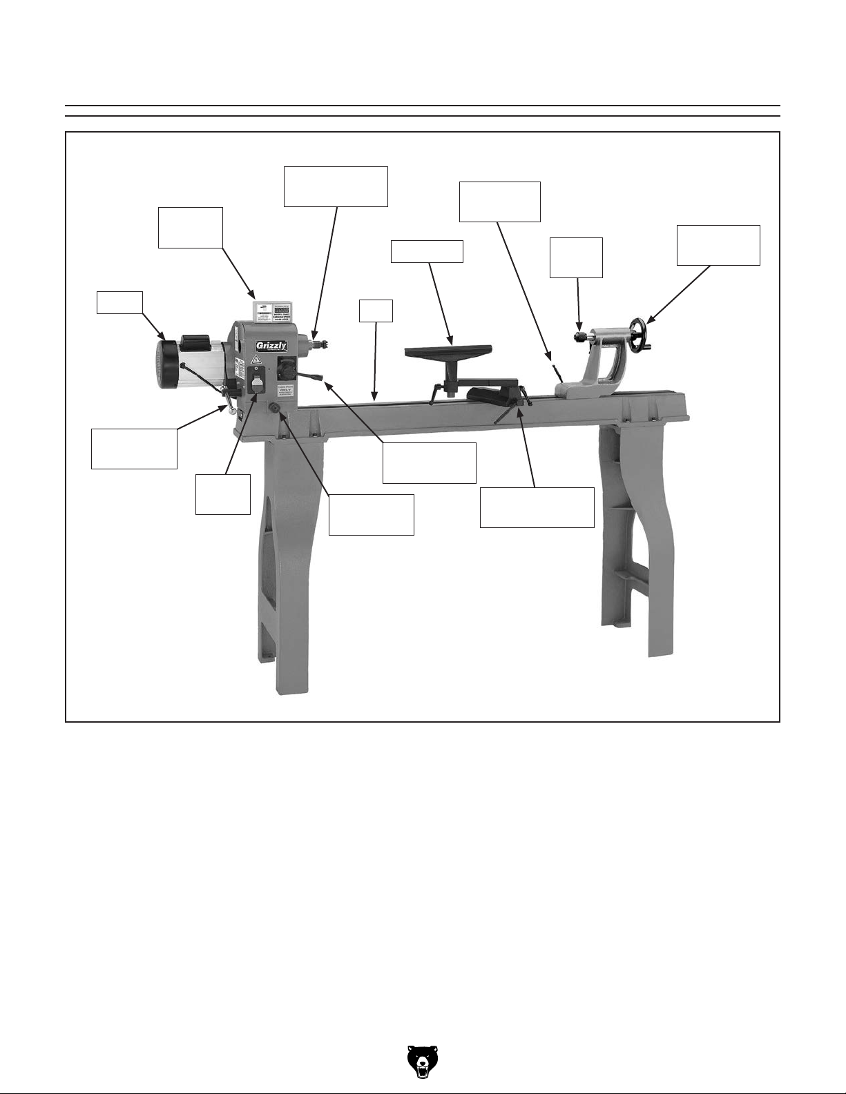
Digital
Readout
Identification
Spindle
& Spur Center
Tool Rest
Tailstock
Lock Lever
Live
Center
Tailstock
Handwheel
Motor
Head
Lock Lever
Power
Switch
Bed
Speed Lever
Head Pivot
Lock Pin
Variable
Tool Rest Base
w/Pivot Arm
Figure 1. Model G0462 identification.
G0462 Wood Lathe (Mfd. Since 11/14)
-3-
Page 6

Machine Data Sheet
MACHINE DATA
SHEET
Customer Service #: (570) 546-9663 · To Order Call: (800) 523-4777 · Fax #: (800) 438-5901
MODEL G0462 WOOD LATHE WITH DIGITAL READOUT
Product Dimensions:
Weight.............................................................................................................................................................. 287 lbs.
Width (side-to-side) x Depth (front-to-back) x Height..................................................................... 72-1/2 x 19 x 48 in.
Footprint (Length x Width)..................................................................................................................... 54 x 13-3/4 in.
Shipping Dimensions:
Type..................................................................................................................................................... Cardboard Box
Content........................................................................................................................................................... Machine
Weight.............................................................................................................................................................. 354 lbs.
Length x Width x Height....................................................................................................................... 18 x 64 x 20 in.
Must Ship Upright................................................................................................................................................... Yes
Electrical:
Power Requirement........................................................................................................... 110V, Single-Phase, 60 Hz
Prewired Voltage.................................................................................................................................................. 110V
Full-Load Current Rating........................................................................................................................................ 14A
Minimum Circuit Size.............................................................................................................................................. 20A
Connection Type....................................................................................................................................... Cord & Plug
Power Cord Included.............................................................................................................................................. Yes
Power Cord Length................................................................................................................................................. 8 ft.
Power Cord Gauge......................................................................................................................................... 16 AWG
Plug Included.......................................................................................................................................................... Yes
Included Plug Type................................................................................................................................................ 5-15
Switch Type.................................................................................................. Paddle Safety Switch w/Removable Key
Motors:
Main
Type................................................................................................................. TEFC Capacitor-Start Induction
Horsepower................................................................................................................................................ 2 HP
Phase............................................................................................................................................ Single-Phase
Amps............................................................................................................................................................ 14A
Speed................................................................................................................................................ 1725 RPM
Power Transfer ............................................................................................................................... V-Belt Drive
Bearings..................................................................................................... Shielded & Permanently Lubricated
Main Specifications:
Operation Information
Swing Over Bed......................................................................................................................................... 16 in.
Distance Between Centers........................................................................................................................ 46 in.
Swing Over Tool Rest................................................................................................................................ 13 in.
Swing Over Tool Rest Base................................................................................................................ 13-1/2 in.
No of Spindle Speeds............................................................................................................................ Variable
Spindle Speed Range.............................................................................................................. 600 – 2400 RPM
Floor to Center Height............................................................................................................................... 43 in.
Headstock Rotation...................................................................................................... 0, 60, 90, 120, 180 deg.
-4-
G0462 Wood Lathe (Mfd. Since 11/14)
Page 7

Spindle Information
Spindle Taper............................................................................................................................................
Spindle Thread Size............................................................................................................................ 1" x 8 TPI
Spindle Thread Direction.................................................................................................................. Right Hand
Spindle Bore............................................................................................................................................. 3/8 in.
Type of Included Spindle Center................................................................................................................. Spur
Tool Rest Information
Tool Rest Width................................................................................................................................... 11-7/8 in.
Tool Rest Post Diameter......................................................................................................................... 25 mm
Tool Rest Post Length........................................................................................................................... 2-1/8 in.
Tool Rest Base Height......................................................................................................................... 1-7/16 in.
Tailstock Information
Tailstock Taper.......................................................................................................................................... MT#2
Type of Included Tailstock Center............................................................................................................... Live
Construction
Bed.......................................................................................................................... Precision-Ground Cast Iron
Frame................................................................................................................................................... Cast Iron
Stand.................................................................................................................................................... Cast Iron
Base..................................................................................................................................................... Cast Iron
Headstock............................................................................................................................................ Cast Iron
Tailstock............................................................................................................................................... Cast Iron
Paint Type/Finish.................................................................................................................................... Enamel
MT#2
Other Specifications:
Country of Origin ................................................................................................................................................ China
Warranty ........................................................................................................................................................... 1 Year
Approximate Assembly & Setup Time .............................................................................................................. 1 Hour
Serial Number Location .................................................................................................................................. ID Label
ISO 9001 Factory .................................................................................................................................................. Yes
CSA, ETL, or UL Certified/Listed ............................................................................................................................ No
Features:
Spindle Tachometer with Digital Readout
Outboard Turning is Easy with Standard Tool Rest Extension
Quick Lock/Release Levers for Tailstock and Headstock
Heavy-Duty Cast Iron Bed and Legs Ensure Stability and Minimize Vibration
G0462 Wood Lathe (Mfd. Since 11/14)
-5-
Page 8

SECTION 1: SAFETY
For Your Own Safety, Read Instruction
Manual Before Operating This Machine
The purpose of safety symbols is to attract your attention to possible hazardous conditions.
This manual uses a series of symbols and signal words intended to convey the level of importance of the safety messages. The progression of symbols is described below. Remember that
safety messages by themselves do not eliminate danger and are not a substitute for proper
accident prevention measures. Always use common sense and good judgment.
Indicates an imminently hazardous situation which, if not avoided,
WILL result in death or serious injury.
Indicates a potentially hazardous situation which, if not avoided,
COULD result in death or serious injury.
Indicates a potentially hazardous situation which, if not avoided,
MAY result in minor or moderate injury. It may also be used to alert
against unsafe practices.
This symbol is used to alert the user to useful information about
NOTICE
proper operation of the machine.
Safety Instructions for Machinery
OWNER’S MANUAL. Read and understand this
owner’s manual BEFORE using machine.
TRAINED OPERATORS ONLY. Untrained operators have a higher risk of being hurt or killed.
Only allow trained/supervised people to use this
machine. When machine is not being used, disconnect power, remove switch keys, or lock-out
machine to prevent unauthorized use—especially
around children. Make workshop kid proof!
DANGEROUS ENVIRONMENTS. Do not use
machinery in areas that are wet, cluttered, or have
poor lighting. Operating machinery in these areas
greatly increases the risk of accidents and injury.
MENTAL ALERTNESS REQUIRED. Full mental
alertness is required for safe operation of machinery. Never operate under the influence of drugs or
alcohol, when tired, or when distracted.
ELECTRICAL EQUIPMENT INJURY RISKS. You
can be shocked, burned, or killed by touching live
electrical components or improperly grounded
machinery. To reduce this risk, only allow qualified
service personnel to do electrical installation or
repair work, and always disconnect power before
accessing or exposing electrical equipment.
DISCONNECT POWER FIRST.
nect machine from power supply BEFORE making
adjustments, changing tooling, or servicing machine.
This prevents an injury risk from unintended startup
or contact with live electrical components.
EYE PROTECTION. Always wear ANSI-approved
safety glasses or a face shield when operating or
observing machinery to reduce the risk of eye
injury or blindness from flying particles. Everyday
eyeglasses are NOT approved safety glasses.
Always discon-
-6-
G0462 Wood Lathe (Mfd. Since 11/14)
Page 9

WEARING PROPER APPAREL. Do not wear
clothing, apparel or jewelry that can become
entangled in moving parts. Always tie back or
coverlong hair. Wearnon-slipfootwearto avoid
accidentalslips,whichcould cause lossofworkpiececontrol.
hAzARdOus dusT. Dust created while using
machinery may cause cancer, birth defects, or
long-term respiratory damage.Be aware ofdust
hazardsassociatedwitheachworkpiecematerial,
andalwayswearaNIOSH-approvedrespiratorto
reduceyourrisk.
hEARING PROTECTION. Always wear hearing protection when operatingor observingloud
machinery. Extended exposure to this noise
withouthearing protectioncancause permanent
hearingloss.
REMOVE AdJusTING TOOLs. Tools left on
machinery can become dangerous projectiles
uponstartup.Neverleavechuckkeys,wrenches,
or any other tools on machine. Always verify
removalbeforestarting!
INTENdEd usAGE. Only use machine for its
intendedpurposeandnevermakemodifications
not approved by Grizzly. Modifying machine or
using it differently than intended may result in
malfunctionormechanicalfailurethatcanleadto
seriouspersonalinjuryordeath!
AWKWARd POsITIONs. Keep proper footing
andbalanceatalltimeswhenoperatingmachine.
Donotoverreach!Avoidawkwardhandpositions
that make workpiece controldifficult orincrease
the
riskofaccidentalinjury.
ChILdREN & BYsTANdERs. Keepchildrenand
bystandersatasafedistancefromtheworkarea.
Stopusingmachineiftheybecomeadistraction.
FORCING MAChINERY.Donotforcemachine.
Itwill dothejob saferandbetter attherate for
whichitwasdesigned.
NEVER sTANd ON MAChINE. Serious injury
may occur if machine is tipped or if thecutting
toolisunintentionallycontacted.
sTABLE MAChINE. Unexpectedmovementduring operation greatly increases risk of injury or
lossofcontrol. Beforestarting,verifymachineis
stableandmobilebase(ifused)islocked.
usE RECOMMENdEd ACCEssORIEs.Consult
thisowner’smanualorthemanufacturerforrecommended accessories.Using improper accessorieswillincreasetheriskofseriousinjury.
uNATTENdEd OPERATION. To reduce the
risk ofaccidental injury, turn machine offand
ensure all moving parts completely stop before
walking away. Never leave machine running
whileunattended.
MAINTAIN WITh CARE.Followallmaintenance
instructions and lubrication schedules to keep
machine in good working condition. A machine
that is
leadingtoseriouspersonalinjuryordeath.
ChECK dAMAGEd PARTs. Regularly inspect
machine for any condition that may affect safe
operation.Immediatelyrepairorreplacedamaged
ormis-adjustedpartsbeforeoperatingmachine.
MAINTAIN POWER CORds. When disconnecting cord-connected machines from power, grab
andpulltheplug—NOTthecord.Pullingthecord
may damage the wires inside. Do not handle
cord/plugwithwethands.Avoidcorddamageby
keepingitawayfromheatedsurfaces,hightraffic
areas,harshchemicals,andwet/damplocations.
improperly maintained could malfunction,
GuARds & COVERs.Guardsandcoversreduce
accidental contact with moving parts or flying
debris. Make sure they are properly installed,
undamaged,andworkingcorrectly.
G0462 Wood Lathe (Mfd. Since 11/14)
EXPERIENCING dIFFICuLT I E s. If at any time
youexperiencedifficultiesperformingtheintendedoperation,stopusingthemachine!Contactour
TechnicalSupportat(570)546-9663.
-7-
Page 10

Additional Safety for Wood Lathes
MAIN INJURY HAZARDS: Death or crushing injury from getting entangled in rotating spindle
or workpiece; death, blindness, or broken bones from being struck by a workpiece that breaks
apart or comes loose during rotation, turning tool kickback, or flying wood chips. To minimize
your risk of these hazards, always heed the following warning information:
INTEGRITY OF STOCK. Verify each workpiece
is free of knots, splits, nails, or foreign material
to ensure it can safely rotate on spindle without
breaking apart or causing turning tool kickback.
WORKPIECE PREPARATION. Before mounting,
cut off waste portions with a bandsaw or other tool
to ensure workpiece has no large edges to catch
turning tool, and it will rotate without dangerous
wobbling.
SECURING LOCKS. Verify tool rest, headstock,
and tailstock are secure before turning lathe ON.
SECURING WORKPIECE. An im p r operl y se c ur ed
workpiece can fly off spindle with deadly force.
Use proven setup techniques and always verify
workpiece is well-secured before starting lathe.
Only use high-quality fasteners with non-tapered
heads for faceplate attachment.
TOOL SUPPORT. An improperly supported tool
may be grabbed or ejected. Adjust tool rest
approximately
above workpiece center line to provide proper
support for turning tool. Firmly hold turning tool
with both hands against tool rest.
TOOL KICKBACK. Occurs when turning tool is
ejected from workpiece with great force, striking
operator or bystanders. Commonly caused by
poor workpiece selection/preparation, improper
tool usage, or improper machine setup or tool rest
adjustment.
ADJUSTMENT TOOLS. Remove all chuck keys,
wrenches, and adjustment tools before turning
lathe ON. A tool left on the lathe can become a
deadly projectile when spindle is started.
1
⁄4" away from workpiece and 1⁄8"
EYE/FACE PROTECTION. Always wear a face
shield and safety glasses when operating lathe.
PROPER APPAREL. Do not wear gloves, necktie
or loose clothing. Keep keep long hair away from
rotating spindle.
SPEED RATES. Select correct spindle speed for
workpiece size, type, shape, and condition. Use
low speeds when roughing or when turning large,
long, or non-concentric workpieces. Allow spindle
to reach full speed before turning.
NEW SETUPS. Test each new setup by starting
spindle rotation at the lowest speed and standing
to the side of the lathe until workpiece reaches full
speed and you can verify safe rotation.
ROUGHING. Use correct tool. Take light cuts,
use low speeds, and firmly support tool with both
hands.
SHARP TOOLS. Only use sharp turning tools—
they cut with less resistance than dull tools. Dull
turning tools can catch or grab and pull your
hands into the rotating workpiece.
STOPPING SPINDLE. Always allow spindle to
completely stop on its own. Never put hands or
another object on spinning workpiece.
ADJUSTMENTS/MAINTENANCE. Make sure
wood lathe is turned OFF, disconnected from
power, and all moving parts a re co mpl ete l y s top pe d
before doing adjustments or maintenance.
MEASURING WORKPIECE. Only measure workpiece after it has stopped. Trying to measure a
spinning workpiece increases entanglement risk.
SAFE CLEARANCES. Before starting spindle,
verify workpiece has adequate clearance by handrotating it through its entire range of motion.
-8-
SANDING/POLISHING. To reduce entanglement
risk, remove tool rest before sanding. Never completely wrap sandpaper around workpiece.
G0462 Wood Lathe (Mfd. Since 11/14)
Page 11

SECTION 2: POWER SUPPLY
Before installing the machine, consider the availability and proximity of the required power supply
circuit. If an existing circuit does not meet the
requirements for this machine, a new circuit must
be installed. To minimize the risk of electrocution,
fire, or equipment damage, installation work and
electrical wiring must be done by an electrician or
qualified service personnel in accordance with all
applicable codes and standards.
Electrocution, fire, or
equipment damage may
occur if machine is not
correctly grounded and
connected to the power
The full-load current rating is the amperage a
machine draws at 100% of the rated output power.
On machines with multiple motors, this is the
amperage drawn by the largest motor or sum of all
motors and electrical devices that might operate
at one time during normal operations.
The full-load current is not the maximum amount
of amps that the machine will draw. If the machine
is overloaded, it will draw additional amps beyond
the full-load rating.
If the machine is overloaded for a sufficient length
of time, damage, overheating, or fire may result—
especially if connected to an undersized circuit.
To reduce the risk of these hazards, avoid overloading the machine during operation and make
sure it is connected to a power supply circuit that
meets the specified circuit requirements.
For your own safety and protection of
Note: Circuit requirements in this manual apply to
a dedicated circuit—where only one machine will
be running on the circuit at a time. If machine will
be connected to a shared circuit where multiple
machines may be running at the same time, consult an electrician or qualified service personnel to
ensure circuit is properly sized for safe operation.
A power supply circuit includes all electrical
equipment between the breaker box or fuse panel
in the building and the machine. The power supply circuit used for this machine must be sized to
safely handle the full-load current drawn from the
machine for an extended period of time. (If this
machine is connected to a circuit protected by
fuses, use a time delay fuse marked D.)
This machine is prewired to operate on a power
supply circuit that has a verified ground and meets
the following requirements:
Availability
Serious injury could occur if you connect
machine to power before completing setup
process. DO NOT connect to power until
instructed later in this manual.
110V Circuit Requirements
Nominal Voltage .............................. 110V–120V
Cycle ..........................................................60 Hz
Phase ........................................... Single-Phase
Power Supply Circuit ......................... 20 Amps
supply.
Full-Load Current Rating
Full-Load Current Rating at 110V ...... 14 Amps
G0462 Wood Lathe (Mfd. Since 11/14)
property, consult an electrician if you are
unsure about wiring practices or electrical
codes in your area.
-9-
Page 12
Improper connection of the equipment-grounding
wire can result in a risk of electric shock. The
wire with green insulation (with or without yellow
stripes) is the equipment-grounding wire. If repair
or replacement of the power cord or plug is necessary, do not connect the equipment-grounding
wire to a live (current carrying) terminal.
Check with a qualified electrician or service personnel if you do not understand these grounding
requirements, or if you are in doubt about whether
the tool is properly grounded. If you ever notice
that a cord or plug is damaged or worn, disconnect it from power, and immediately replace it with
a new one.
We do not recommend using an extension cord
with this machine.
cord, only use it if absolutely necessary and only
on a temporary basis.
Extension cords cause voltage drop, which may
damage electrical components and shorten motor
life. Voltage drop increases as the extension cord
size gets longer and the gauge size gets smaller
(higher gauge numbers indicate smaller sizes).
Any extension cord used with this machine must
contain a ground wire, match the required plug
and receptacle, and meet the following requirements:
Grounding & Plug Requirements
it will not fit the outlet, have a qualified
This machine MUST be grounded. In the event
of certain malfunctions or breakdowns, grounding
reduces the risk of electric shock by providing a
path of least resistance for electric current.
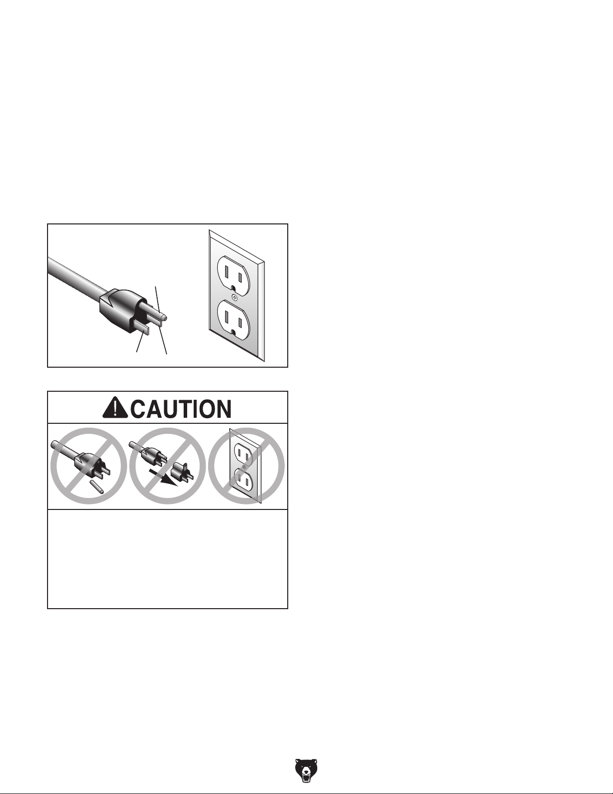
This machine is equipped with a power cord that
has an equipment-grounding wire and a grounding plug (similar to the figure below). The plug
must only be inserted into a matching receptacle
(outlet) that is properly installed and grounded in
accordance with all local codes and ordinances.
GROUNDED
5-15 RECEPTACLE
Grounding Prong
5-15 PLUG
Extension Cords
If you must use an extension
Neutral Hot
Figure 2. Typical 5-15 plug and receptacle.
SHOCK HAZARD!
Two-prong outlets do not meet the grounding
requirements for this machine. Do not modify
or use an adapter on the plug provided—if
electrician install the proper outlet with a
verified ground.
-10 -
Minimum Gauge Size ...........................14 AWG
Maximum Length (Shorter is Better).......50 ft.
G0462 Wood Lathe (Mfd. Since 11/14)
Page 13
SECTION 3: SETUP
Your machine was carefully packaged for safe
transportation. Remove the packaging materials
from around your machine and inspect it. If you
discover any damage, please call us immediately
at (570) 546-9663
Save the containers and all packing materials for
possible inspection by the carrier or its agent.
Otherwise, filing a freight claim can be difficult.
When you are completely satisfied with the condition of your shipment, inventory the contents.
Keep children and pets away
from plastic bags or packing
materials shipped with this
The following is a list of items shipped with your
machine. Before beginning setup, lay these items
out and inventory them.
If any non-proprietary parts are missing (e.g. a
nut or a washer), we will gladly replace them; or
for the sake of expediency, replacements can be
obtained at your local hardware store.
Unpacking
for advice.
SUFFOCATION HAZARD!
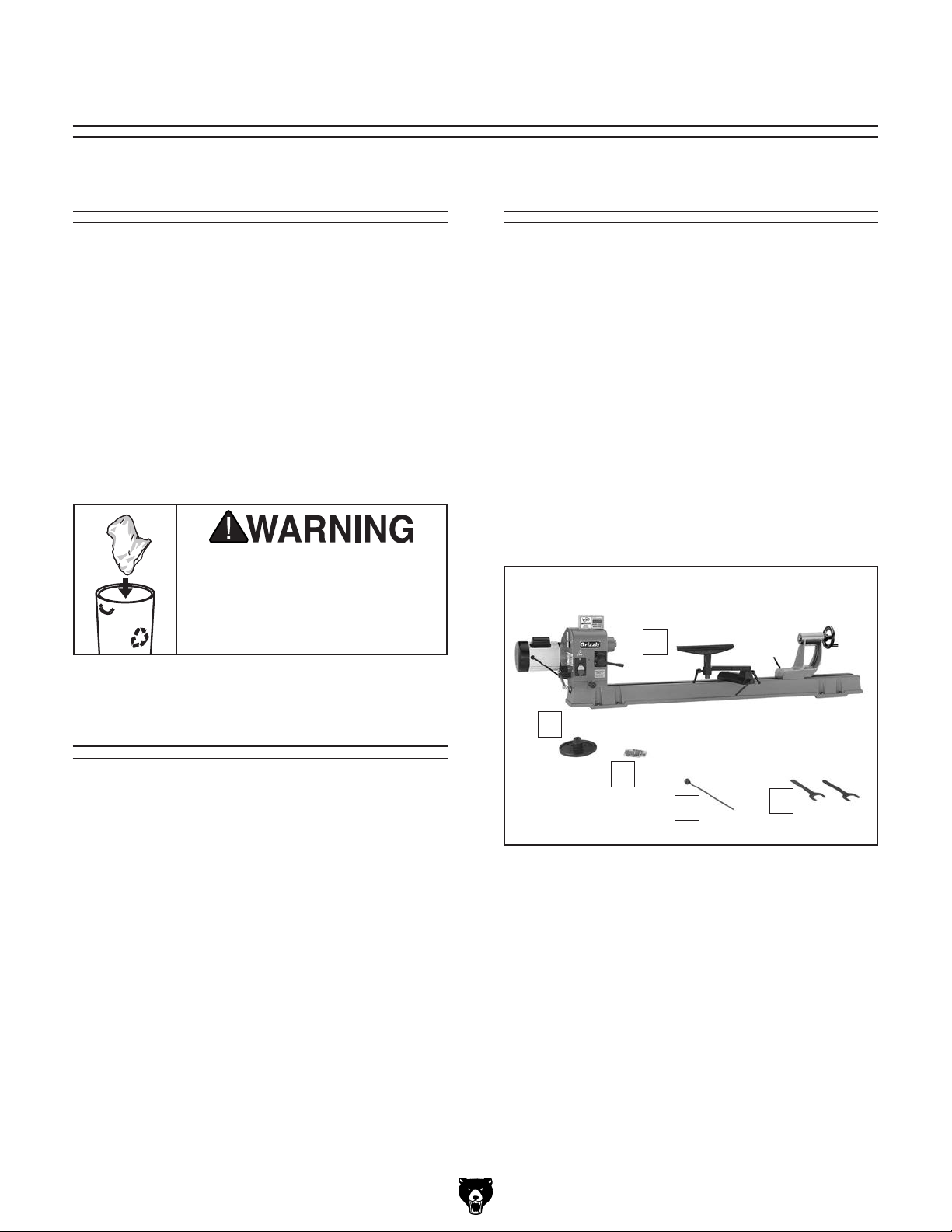
Inventory
Box 1 Inventory (Figure 3) Qty
A. Lathe Unit ................................................... 1
B. Faceplate 6" ............................................... 1
C. Hardware Bag ............................................ 1
D. Knockout Tool ............................................. 1
E. Flat Wrenches 32mm ................................. 2
machine. Discard immediately.
Needed for Setup
The following are needed to complete the setup
process, but are not included with your machine.
Description Qty
• Additional People .........................At Least 2
• Safety Glasses ............... 1 For Each Person
• Cleaner/Degreaser (Page 13) .... As Needed
• Disposable Shop Rags ............... As Needed
• Mounting Hardware (Page 15) ... As Needed
• Precision Level ........................................... 1
• Measuring Tape .......................................... 1
G0462 Wood Lathe (Mfd. Since 11/14)
A
B
C
D
Figure 3. Box 1 inventory.
E
-11-
Page 14
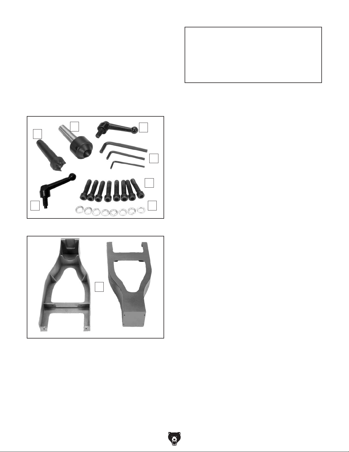
Hardware Bag Inventory (Figure 4) Qty
F. Spur Center ................................................ 1
G. Live Center ................................................. 1
H. Tool Rest Lock Lever .................................. 1
I. Hex Wrenches 3mm, 4mm, 6mm ......1 Each
J. Cap Screws M8-1.25 x 35 .......................... 8
K. Lock Washers 8mm.................................... 8
L. Quill Lock Lever .......................................... 1
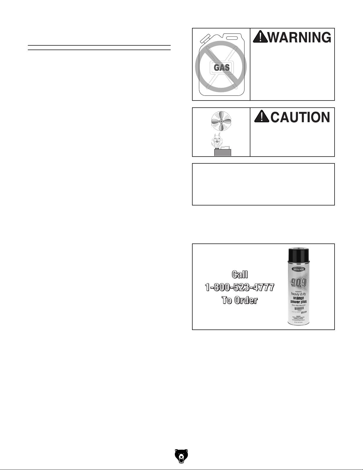
Box 2 Inventory (Figure 5) Qty
M. Stand Legs ................................................. 2
NOTICE
If you cannot find an item on this list, carefully check around/inside the machine and
packaging materials. Often, these items get
lost in packaging materials while unpacking or they are pre-installed at the factory.
G
F
Figure 4. Hardware bag inventory.
M
H
I
J
KL
-12-
Figure 5. Box 2 inventory.
G0462 Wood Lathe (Mfd. Since 11/14)
Page 15
The unpainted surfaces of your machine are
coated with a heavy-duty rust preventative that
prevents corrosion during shipment and storage.
This rust preventative works extremely well, but it
will take a little time to clean.
Be patient and do a thorough job cleaning your
machine. The time you spend doing this now will
give you a better appreciation for the proper care
of your machine's unpainted surfaces.
There are many ways to remove this rust preventative, but the following steps work well in a wide
variety of situations. Always follow the manufacturer’s instructions with any cleaning product you
use and make sure you work in a well-ventilated
area to minimize exposure to toxic fumes.
Before cleaning, gather the following:
• Disposable rags
• Cleaner/degreaser (WD•40 works well)
• Safety glasses & disposable gloves
• Plastic paint scraper (optional)
Basic steps for removing rust preventative:
1.
2.
3.
4.
Many cleaning solvents
work in a well-ventilated
Avoid chlorine-based solvents, such as
Cleanup
Gasoline and petroleum
products have low flash
points and can explode
or cause fire if used to
clean machinery. Avoid
using these products
to clean machinery.
Put on safety glasses.
Coat the rust preventative with a liberal
amount of cleaner/degreaser, then let it soak
for 5–10 minutes.
Wipe off the surfaces. If your cleaner/degreas-
er is effective, the rust preventative will wipe
off easily. If you have a plastic paint scraper,
scrape off as much as you can first, then wipe
off the rest with the rag.
are toxic if inhaled. Only
area.
NOTICE
acetone or brake parts cleaner, that may
damage painted surfaces.
T23692—Orange Power Degreaser
A great product for removing the waxy shipping
grease from your machine during clean up.
Figure 6. T23692 Orange Power Degreaser.
Repeat Steps 2–3 as necessary until clean,
then coat all unpainted surfaces with a quality
metal protectant to prevent rust.
G0462 Wood Lathe (Mfd. Since 11/14)
-13-
Page 16

Site Considerations
Wall
Recommended 48"
For Outboard Turning
77"
19"
30"
Illustration Not To Scale
Weight Load
Physical Environment
Place this machine near an existing power source.
Shadows, glare, or strobe effects that may distract
Refer to the Machine Data Sheet for the weight
of your machine. Make sure that the surface upon
which the machine is placed will bear the weight
of the machine, additional equipment that may be
installed on the machine, and the heaviest workpiece that will be used. Additionally, consider the
weight of the operator and any dynamic loading
that may occur when operating the machine.
Space Allocation
Consider the largest size of workpiece that will
be processed through this machine and provide
enough space around the machine for adequate
operator material handling or the installation of
auxiliary equipment. With permanent installations,
leave enough space around the machine to open
or remove doors/covers as required by the maintenance and service described in this manual.
See below for required space allocation.
Children or untrained people
may be seriously injured by
this machine. Only install in an
access restricted location.
The physical environment where the machine is
operated is important for safe operation and longevity of machine components. For best results,
operate this machine in a dry environment that is
free from excessive moisture, hazardous chemicals, airborne abrasives, or extreme conditions.
Extreme conditions for this type of machinery are
generally those where the ambient temperature
range exceeds 41°–104°F; the relative humidity
range exceeds 20–95% (non-condensing); or the
environment is subject to vibration, shocks, or
bumps.
Electrical Installation
Make sure all power cords are protected from
traffic, material handling, moisture, chemicals,
or other hazards. Make sure to leave access to
a means of disconnecting the power source or
engaging a lockout/tagout device, if required.
Lighting
Lighting around the machine must be adequate
enough that operations can be performed safely.
or impede the operator must be eliminated.
-14-
Figure 7. Minimum working clearances.
G0462 Wood Lathe (Mfd. Since 11/14)
Page 17

Anchoring machinery to the floor prevents tipping
or shifting and reduces vibration that may occur
during operation, resulting in a machine that runs
slightly quieter and feels more solid.
If the machine will be installed in a commercial or
workplace setting, or if it is permanently connected
(hardwired) to the power supply, local codes may
require that it be anchored to the floor.
If not required by any local codes, fastening the
machine to the floor is an optional step. If you
choose not to do this with your machine, we
recommend placing it on machine mounts, as
these provide an easy method for leveling and
they have vibration-absorbing pads.
Anchoring to Floor
Lag shield anchors with lag screws (see below)
are a popular way to anchor machinery to a
concrete floor, because the anchors sit flush
with the floor surface, making it easy to unbolt
and move the machine later, if needed. However,
anytime local codes apply, you MUST follow the
anchoring methodology specified by the code.
Assembly
To mount the lathe to the stand:
1. Stand the legs up approximately 41" apart
and get them reasonably aligned, as shown
in Figure 9.
Anchoring to Concrete Floors
Lag Screw
Machine Base
Concrete
Figure 8. Popular method for anchoring
machinery to a concrete floor.
G0462 Wood Lathe (Mfd. Since 11/14)
Flat Washer
Lag Shield Anchor
Drilled Hole
41"
Figure 9. Stand legs approximately 41" apart to
prepare for mounting the lathe.
2. Use the help of additional people to carefully lift the lathe onto the legs and align the
mounting holes.
Note: The headstock end is the heaviest and
usually requires two people lifting at that end.
3. Secure the lathe to the legs with the (8)
M8-1.25 x 35 cap screws and 8mm lock
washers, as shown in Figure 10.
x 8
Figure 10. Securing lathe to the stand leg.
-15-
Page 18

4. Install the tool rest lock lever to secure the
tool rest, as shown in Figure 11.
Figure 11. Installing handle into tool rest.
Quill Keyway
Test Run
Loose hair and clothing
could get caught in machinery and cause serious personal injury. Keep loose
clothing and long hair away
from moving machinery.
Once assembly is complete, test run your machine
to make sure it runs properly and is ready for
regular operation.
5. Install the lever into the tailstock so that the
end of it mates with the quill keyway (see
Figure 12).
Note: Make sure the dog-point end of the
lock lever fits into the quill keyway so that
the quill can move in and out of the tailstock
without rotating.
Quill
Keyway
Quill
Lock Lever
Figure 12. Quill lock lever.
6. Attach the digital readout to the top of the
head with the pre-installed Phillips head
screws, lock washers, and flat washers, as
shown in Figure 13.
The test run consists of verifying the following:
1) The motor powers up and runs correctly, and
2) the safety disabling mechanism on the switch
works correctly.
If, during the test run, you cannot easily locate
the source of an unusual noise or vibration, stop
using the machine immediately, then review
Troubleshooting on Page 35.
If you still cannot remedy a problem, contact our
Tech Support at (570) 546-9663 for assistance.
To test run the machine:
1. Make sure you have read the safety instruc-
tions at the beginning of the manual and that
the machine is set up properly.
2. Make sure all tools and objects used during
setup are cleared away from the machine.
3. Connect the machine to the power source.
4. Verify that the machine is operating correctly
by turning the machine ON.
-16 -
—When operating correctly, the machine
runs smoothly with little or no vibration or
rubbing noises.
x 2
— Investigate and correct strange or unusual
noises or vibrations before operating the
machine further. Always disconnect the
machine from power when investigating or
correcting potential problems.
Figure 13. Digital readout installed.
G0462 Wood Lathe (Mfd. Since 11/14)
Page 19

5. Turn the machine OFF.
6. Remove the switch disabling key, as shown
in Figure 14.
Figure 14. Example of removing switch key from
paddle switch.
10. Test the variable speed by pulling the speed
lever out (Figure 15) and slowly adjusting it
left and right.
Variable
Speed Lever
Figure 15. Variable speed lever.
7. Try to start the machine with the paddle
switch.
—If the machine does not start, the switch
disabling feature is working as designed.
—If the machine starts, immediately stop the
machine. The switch disabling feature is
not working correctly. This safety feature
must work properly before proceeding with
regular operations. Call Tech Support for
help.
The spindle speed lever adjusts the pulley
width to change the spindle speed. To prevent damage to this mechanism, the lathe
MUST be running before using the variable
speed lever.
8. Re-insert the switch disabling key.
— The machine should speed up and slow
down as you move the lever. If this is the
case, then the test run is over and your
machine is ready for normal operations.
—If the lathe has problems changing speeds,
turn the lathe OFF, disconnect it from
power, and refer to the troubleshooting
chart on Page 35, or call our Tech Support
at (570) 546-9663 for additional help.
9. Turn the lathe ON.
G0462 Wood Lathe (Mfd. Since 11/14)
-17-
Page 20

SECTION 4: OPERATIONS
The purpose of this overview is to provide the novice machine operator with a basic understanding
of how the machine is used during operation, so
the
discussed later
in this manual
Due to the generic nature of this overview, it is
not
more about specific operations,
manual and
rienced
research outside of this manual by reading "howto" books, trade magazines, or websites.
To reduce your risk of
serious injury, read this
entire manual BEFORE
To reduce risk of eye injury from flying
Operation Overview
To complete a typical operation, the operator
does the following:
1. Examines the workpiece to make sure it is
suitable for turning. No extreme bows, knots,
or cracks should exist.
machine controls/components
are easier to understand.
intended to be an instructional guide. To learn
read this entire
seek additional training from expe
machine operators, and do additional
using machine.
chips or lung damage from breathing dust,
always wear safety glasses and a respirator
when operating this machine.
2. Prepares and trims the workpiece to make it
roughly concentric.
3. Installs the workpiece between centers, or
attaches it to a faceplate or chuck.
1
4. Adjusts the tool rest to
centerline, and sets the minimum clearance
between the workpiece and the lip of the tool
rest to
5. Rotates the workpiece by hand to verify
that the spindle and workpiece rotate freely
throughout the full range of motion.
6. Ties back loose hair and clothing, and puts
on face shield and respirator. Takes all other
required safety precautions.
7. Starts the lathe, adjusts the lathe speed, and
carefully begins the turning operation, keeping the chisel against the tool rest the entire
time it is cutting.
1
⁄4".
⁄8" above the workpiece
If you are not experienced with this type
of machine, WE STRONGLY RECOMMEND
that you seek additional training outside of
this manual. Read books/magazines or get
formal training before beginning any projects. Regardless of the content in this section, Grizzly Industrial will not be held liable
for accidents caused by lack of training.
-18-
G0462 Wood Lathe (Mfd. Since 11/14)
Page 21

Stock Inspection &
Requirements
Some workpieces are not safe to turn or may
require modification before they are safe to
turn. Before turning a workpiece, inspect all
workpieces for the following:
• Workpiece Type:
This machine is intended for cutting natural
and man-made wood products, and some
plastics. Never attempt to cut any metal,
stone, or rubber workpiece; cutting these
materials can lead to machine damage or
severe injury.
Adjusting Head
The Model G0462 headstock can be positioned
anywhere along the bed and pivoted up to 180˚.
To position the headstock along the length of
the bed:
1. DISCONNECT LATHE FROM POWER!
2. Loosen the head lock lever shown in
Figure 16.
• Foreign Objects:
Nails, staples, dirt, rocks and other foreign
objects are often embedded in wood. While
cutting, these objects can become dislodged
and hit the operator, cause tool grab, or break
the turning tool, which might then fly apart.
Always visually inspect your workpiece for
these items. If they can't be removed, DO
NOT turn the workpiece.
• Large/Loose Knots:
Loose knots can become dislodged during
the turning operation. Large knots can cause
a workpiece to completely break in half during turning and cause machine damage and
personal injury. Choose workpieces that do
not have large/loose knots.
• Wet or "Green" Stock:
Cutting wood with a moisture content over
20% causes unnecessary wear on tooling
blades, increases the risk of tool grab, and
yields poor results.
Head Lock
Lever
Figure 16. Head lock lever.
3. Slide the headstock to the desired position,
then retighten the lock lever.
Note: The large hex nut under the headstock
may require occasional adjustment to ensure
proper clamping pressure to the bed. Turn
the hex nut in small increments to fine tune
the clamping pressure, as needed.
• Excessive Warping:
Workpieces with excessive bowing or twist-
ing are unstable and unbalanced. Never turn
these workpieces at high speed, or instability
will be magnified and the workpiece can be
ejected from the lathe causing impact injures.
Only turn concentric workpieces!
G0462 Wood Lathe (Mfd. Since 11/14)
If the lathe head unexpectedly moves during
operation, the tool and your hand could be
drawn into the spinning workpiece resulting
in death or crushing injuries. ALWAYS make
sure the head lock lever is tight and the
head pivot pin is seated before operation.
-19 -
Page 22

To pivot the headstock:
1. DISCONNECT LATHE FROM POWER!
2. Make sure the head lock lever is tight.
Adjusting Tailstock
Position
3. Pull the pivot lock pin out (see Figure 17) and
pivot the headstock clockwise 90˚ or 180˚, as
shown in Figure 18.
Pivot
Lock Pin
Head
Lock Lever
Figure 17. Pivot lock pin location.
The tailstock is equipped with a cam-action
clamping system to secure it. When the lock lever
is tightened, a locking plate lifts up and secures
the tool rest to the bed.
To reposition the tailstock along the bed, loosen
the tailstock lock lever (see Figure 19), move the
tailstock to the desired position, then retighten the
lock lever.
Note: If the lock lever does not securely clamp the
tailstock down onto the bed, loosen or tighten the
hex nut located on the underside of the tailstock in
small increments to achieve the proper clamping
pressure.
Tailstock
Lock Lever
Figure 18. Head set at 90˚ and 180˚.
4. Release the pivot lock pin. Make sure the pin
has engaged in its detent by trying to rotate
the headstock.
-20-
Figure 19. Tailstock lock lever.
G0462 Wood Lathe (Mfd. Since 11/14)
Page 23

Adjusting Tool Rest
The tool rest is equipped with a cam-action clamping system to secure it. When the base lock lever
is tightened, a clamping plate lifts up and secures
the tool rest to the bed.
If tool rest unexpectedly moves during operation, the tool and your hand could be
drawn into the spinning workpiece resulting in death or crushing injuries. ALWAYS
make sure all tool rest locks are tight before
beginning operation.
For safe and good turning results, we recommend
1
positioning the tool rest approximately
from the workpiece, and approximately
⁄4" away
1
⁄8" above
the workpiece center line (see Figure 21).
1
Workpiece
⁄4"
Distances
1
⁄8"
Center Line
Tool Rest
The Model G0462 comes with a three-way adjustable tool rest (see Figure 20).
• Use the base lock lever to secure the tool rest
along the length of the bed.
• Use the pivot arm lock lever to secure the tool
rest at a working distance from the workpiece.
• Use the tool rest lock lever to adjust the
height and angle of the tool rest relative to the
workpiece.
Base
Lock Lever
Figure 21. Tool rest position relative to the
workpiece.
Tool Rest
Lock Lever
Pivot Arm
Lock Lever
Figure 20. Tool rest controls.
G0462 Wood Lathe (Mfd. Since 11/14)
-21-
Page 24

removin spur
Installing/Removing
Spur Center
The included MT#2 spur center installs in the
spindle and forces the workpiece to spin with the
spindle.
Typically, the spur center is driven into the
workpiece (see Spindle Turning on Page 27 for
detailed instructions), then the center is inserted
with the workpiece into the spindle.
Installing Spur Center
1. DISCONNECT LATHE FROM POWER!
2. Move the tailstock and tool rest a safe work-
ing distance from the headstock.
3. If the faceplate is installed, remove it (refer to
Page 24 for detailed instructions).
Removing Spur Center
1. DISCONNECT LATHE FROM POWER!
2. Hold a clean rag under the spindle or wear a
glove to catch the center when you remove it.
3. Insert the knockout tool through the outboard
end of the spindle and firmly tap the center
until it breaks loose (see Figure 23).
Knockout Tool
4. Make sure the spur center and the inside of
the spindle are free of debris and oily substances that could interfere with proper mating of the parts.
5. Insert the tapered end of the center into the
spindle, then push it in with a quick, firm
motion (see Figure 22).
Spur Center
Figure 23. Removing spur center using the
knockout tool.
Before beginning any turning operation
that uses the live center installed into the
tailstock quill, make sure the spur and
live centers are properly aligned (refer to
Aligning Centers on Page 37 for detailed
instructions). Failure to heed this warning
could result in the workpiece being thrown
from the lathe, resulting in death or serious
personal injury.
Figure 22. Inserting spur center into spindle.
6. Make sure the center is securely installed by
attempting to pull it out by hand—a properly
installed center will not pull out by hand.
-22-
G0462 Wood Lathe (Mfd. Since 11/14)
Page 25

Installing/Removing
Live Center
The MT#2 live center installs into the tailstock quill
and rotates with the workpiece.
6. Rotate the quill handwheel to draw the quill
back into the tailstock as far as possible without forcing the center to release.
Note: The more the quill is drawn back into
the tailstock, the greater the workpiece support.
Installing Live Center
1. Move the tailstock a safe working distance
from the head and tool rest.
2. Loosen the quill lock lever, then rotate the quill
handwheel clockwise until the quill extends
out from the tailstock about 1", as shown in
Figure 24.
Quill
Live Center
Quill
Lock Lever
Figure 24. Installing the live center into the
tailstock.
7. Tighten the quill lock lever to hold the quill
and center in place.
The tailstock quill lock lever MUST be tight
and firmly secure the quill in place before
beginning operation. Also, the quill should
not protrude from the tailstock more than
2" or the quill will not adequately support
the workpiece. Otherwise, the workpiece
could come loose and fly at the operator
or bystanders resulting in death or serious
personal injury.
Removing Live Center
1. Loosen the quill lock lever.
2. Hold a clean rag under the center or wear a
glove to catch the center when you remove it.
3. Rotate the quill handwheel counterclockwise
to retract the quill back into the tailstock until
the center is forced out.
3. Make sure the live center and the inside of
the quill are free of debris and oil substances
that could interfere with the proper mating of
these parts.
4. Insert the tapered end of the live center into
the quill with a quick, firm motion.
5. Make sure the center is secure by attempting
to pull it out by hand—a properly installed
center will not pull out by hand.
G0462 Wood Lathe (Mfd. Since 11/14)
-23-
Page 26

Installing/Removing
Faceplate
The faceplate is used when you need to remove
material from the face of the workpiece, such as
during hollowing operations. The faceplate can be
installed only if the spur center is removed from
the spindle.
To install the faceplate:
1. DISCONNECT LATHE FROM POWER!
2. If the spur center is installed, remove it (refer
to Page 22 for detailed instructions).
3. Make sure the internal threads of the face-
plate and the threads of the spindle are free
of any debris, then wipe the threads with a
lightly oiled rag to aid in the installation and
removal.
4. Thread the faceplate onto the spindle clockwise.
5. Use the two included 32mm flat wrenches to
tighten the faceplate, as shown in Figure 25.
Figure 25. Tightening the faceplate onto the
spindle.
To remove the faceplate, perform Steps 3–4 in
reverse.
For detailed instructions on mounting a workpiece
to the faceplate, refer to Faceplate Turning on
Page 29.
-24-
G0462 Wood Lathe (Mfd. Since 11/14)
Page 27

Adjusting Spindle
Speed
Spindle speed must be adjusted while lathe
is running. Adjusting spindle speed while
machine is not in operation could result in
permanent damage to the machine not covered under warranty.
The Model G0462 is engineered to operate
between 600 and 2400 RPM's. Due to the design
of the pulley system, RPM's outside of this range
cannot be attained.
Use the digital readout as a guide. Select a speed
within the set range by pulling out the speed
control lever and turning it to the right to increase
RPM or to the left to decrease the RPM (see
Figure 26).
Variable
Speed Lever
Always choose the correct spindle speed
for your operation. Using the wrong speed
may lead to the workpiece breaking loose
or being thrown from the lathe at a high rate
of speed, causing fatal or severe impact
injuries.
Refer to the chart in Figure 27 to help choose the
correct spindle speed. Note that both the diameter
of the workpiece and the type of cutting should be
considered when determining the proper spindle
speed.
Diameter
of Work-
piece
Under 2" 1520 2400
2–4" 760 1600
4–6"
6–8"
8–10"
10–12"
12–14"
Roughing
RPM
Slowest
available
Slowest
available
Slowest
available
Slowest
available
Slowest
available
Figure 27. Typical spindle speed
recommendations.
General
Cutting
RPM
1080 1650
810 1240
Slowest
available
Slowest
available
Slowest
available
Finishing
Fastest
available
Fastest
available
RPM
1000
830
710
Figure 26. Speed lever.
When turning a workpiece where a lot of material must be removed and a rough finish does not
matter, low range, which has more torque, is best.
When turning a workpiece where a clean finish is
required, and only light cuts are made, high range
is best. Mid range is a compromise between the
two ranges. Use the speed lever to adjust the
spindle speed within each range.
G0462 Wood Lathe (Mfd. Since 11/14)
-25-
Page 28

Selecting Turning
Tools
Lathe tools come in a variety of shapes and sizes
and usually fall into five major categories.
Refer to Accessories on Page 31 for examples of
recommended wood chisels from Grizzly.
• Gouges—Mainly used for rough cutting,
detail cutting, and cove profiles. The rough
gouge is a hollow, double-ground tool with
a round nose, and the detail gouge is a hollow, double-ground tool with either a round or
pointed nose. Figure 28 shows an example
of a gouge.
• Scrapers—Mainly used where access for
other tools is limited, such as hollowing operations. This is a flat, double-ground tool that
comes in a variety of profiles (Round Nose,
Spear Point, Square Nose, etc.) to match
many different contours. Figure 30 shows an
example of a round nose scraper.
Figure 30. Round nose scraper.
• Parting Tools—Used for sizing and cutting off work. This is a flat tool with a sharp
pointed nose that may be single- or doubleground. Figure 31 shows an example of a
parting tool.
Figure 28. Gouge.
• Skew Chisel—A very versatile tool that can
be used for planing, squaring, V-cutting,
beading, and parting off. The skew chisel
is flat, double-ground with one side higher
than the other (usually at an angle of 20-40˚).
Figure 29 shows an example of a skew
chisel.
Figure 29. Skew chisel.
Figure 31. Parting tool.
• Specialty Tools—These are the unique,
special function tools to aid in hollowing, bowl
making, cutting profiles, etc.
-26-
G0462 Wood Lathe (Mfd. Since 11/14)
Page 29

Workpiece
Workpiece
Center
Pencil Lines
Marked Diagonally
Across Corners
Spindle Turning
Spindle turning, as shown in Figure 32, is the
operation performed when a workpiece is mounted between the spindle and quill centers.
To set up a spindle turning operation:
1. Mark both ends of your workpiece by draw-
ing diagonal lines from corner to corner. The
intersection point of these lines will show you
the center of your workpiece. See the illustration in Figure 33 for details.
Figure 32.
Before beginning any turning operation
that uses the live center installed into the
tailstock quill, make sure the spur and
live centers are properly aligned (refer to
Aligning Centers on Page 37 for detailed
instructions). Failure to heed this warning
could result in the workpiece being thrown
from the lathe resulting in death, blindness,
or broken bones.
Typical spindle turning operation.
Figure 33. Workpiece marked diagonally from
corner to corner to determine the center.
2. Use a wood mallet to tap the point of the spur
center into the workpiece where the lines
intersect so that it leaves a center mark, then
remove the center. Do this to both ends of the
workpiece.
1
3. Use a
the center mark on the workpiece end that
will be mounted on the spindle spur center.
4. To help embed the spur center into the
workpiece, cut
same workpiece end along the diagonal lines
marked in Step 1.
5. If your workpiece is over 2" x 2", cut the corners off the workpiece length-wise to make
turning the corners safer and easier.
⁄4" drill bit to make a 1⁄4" deep hole at
1
⁄8" deep saw kerfs into the
G0462 Wood Lathe (Mfd. Since 11/14)
-27-
Page 30

Workpiece
Center Line
Distances
Tool Rest
1
⁄8"
1
⁄4"
6. Use a wood mallet to embed the spur center
at least
1
⁄4" into the workpiece end center
mark, as illustrated in Figure 34.
¼"
Figure 34. Spur center properly embedded.
7. With the workpiece still attached, insert the
spur center into the spindle.
8. With the live center installed in the quill, draw
the quill back into the spindle as far as possible without forcing the center to release.
Note: This will give the quill and center the
greatest amount of support to safely hold the
workpiece during operation.
9. Loosen the tailstock lock lever, slide the
tailstock toward the workpiece until the live
center touches the workpiece centerpoint,
then lock the tailstock in this position.
1
11. Position the tool rest approximately
from the workpiece and approximately
⁄4" away
1
⁄8"
above the center line, as illustrated in Figure
35.
Figure 35. Tool rest set 1⁄8" above the
1
center line and
⁄4" away from workpiece.
12. Test the setup by hand-turning the workpiece
to make sure there is enough clearance all
the way around before turning the lathe ON.
Spindle Turning Tips
• When turning the lathe ON, stand outside the
path of the rotating workpiece until the lathe
reaches full speed and you can verify that the
lathe will not throw the workpiece.
• Use the slowest speed when starting or stopping the lathe, and when rough cutting.
10. Use the quill handwheel to push the live
-28-
1
center into the workpiece at least a
⁄4", then
tighten the quill lock lever to secure the center and quill.
Do not press the live center into the
workpiece too firmly or the center bearings
will bind and overheat. Likewise, do not
press the center too lightly or the workpiece
could come loose and spin off the lathe. Use
good judgement. Serious personal injury
could result if care is not taken in this procedure.
• Select the correct speed for the size of
the workpiece you are turning. Use slower
speeds for large workpieces (4" diameter and
over); use the middle range speeds for medium sized workpieces (2"–4" diameter); and
use faster speeds for small sized workpieces
(under 2" in diameter).
• Keep the turning tool on the tool rest the
ENTIRE time that it is approaching the
workpiece and is in contact with it.
• Learn the correct techniques for each tool
you will use. If you are unsure, read books or
magazines about lathe techniques and seek
training from experienced users.
G0462 Wood Lathe (Mfd. Since 11/14)
Page 31

Faceplate Turning
Faceplate turning, as shown in Figure 36, is when
a workpiece is mounted to the faceplate that is
then mounted to the spindle. This type of turning
is usually done with open-faced workpieces like
bowls or plates.
2. Use the mark made in Step 1 to center the
faceplate onto the workpiece back, then
attach it with wood screws that do not have
tapered heads as shown in Figure 38.
Figure 38. Attaching the faceplate to a backing
block, which is glued to the workpiece.
3. Thread the faceplate onto the spindle and
tighten securely.
Figure 36. Typical faceplate turning operation.
Attaching Faceplate to Spindle
1. Use the procedure in Spindle Turning on
Page 27 to mark the center of the workpiece.
Note: Cut off the excess corners of the
workpiece to make it as close to "round" as
possible.
DO NOT use screws with tapered heads
to attach the faceplate because they could
split the faceplate, or the screws could snap
off during operation. See the illustration in
Figure 37 for examples.
Correct Incorrect
Using a Backing Block
If wood screws cannot be used to attach the faceplate to the workpiece, then use a backing block
that is securely glued to the workpiece.
To mount your workpiece to a backing block:
1. Make the backing block from a piece of scrap
wood that is flat on both sides and free of
knots or splits.
2. Locate and mark the center of both the
workpiece and the backing block.
1
3. Drill a
of the backing block.
4. Looking through the hole in the backing block
to line it up with the center of the workpiece,
glue and clamp the backing block to the
workpiece.
⁄4" hole completely through the center
Figure 37. Correct screw type for faceplate
attachment.
G0462 Wood Lathe (Mfd. Since 11/14)
Note: Allow the glue joint to completely cure
according to the glue manufacturer's instructions.
5. Follow steps 1-2 in Attaching Faceplate to
Spindle to attach the faceplate to the backing
block.
-29-
Page 32

Outboard Turning Sanding/Finishing
Sandpaper
Workpiece
Using the Lathe
Outboard turning is a variation of faceplate turning and is usually done when stock diameter is
greater than 12''. For the size of the Model G0462
and its minimum turning speed, we recommend a
maximum diameter of 17'' for outboard turning.
The lathe setup at 90˚ for outboard turning uses
the tool rest with the pivot arm extended, as
shown in Figure 39.
The lathe can be used for finishing procedures
after the turning operations are complete and
before removing the workpiece from the lathe,
such as sanding, polishing, and applying finishes
by hand (see Figure 41 for an example).
Note: When using the lathe to sand or finish the
workpiece, remove the tool rest to prevent entanglement hazards. Use the slowest speed for safer
control and better results.
Figure 39. Headstock set at 90˚.
Figure 40 depicts the lathe setup at 180˚ for out-
board turning.
Note: When turning in this manner, you must use
a free standing tool rest (not supplied).
Figure 40. Headstock set at 180˚.
Figure 41. Typical sanding operation.
Wrapping the sandpaper completely around
the workpiece could pull
your hands into the moving workpiece and may
cause injury. Never wrap
sandpaper completely
around the workpiece!
-30-
G0462 Wood Lathe (Mfd. Since 11/14)
Page 33

ACCESSORIES
order online at www.grizzly.com or call 1-800-523-4777
Installing unapproved accessories may
SECTION 5: ACCESSORIES
cause machine to malfunction, resulting in
serious personal injury or machine damage.
To reduce this risk, only install accessories
recommended for this machine by Grizzly.
NOTICE
Refer to our website or latest catalog for
additional recommended accessories.
H8034 —3" 3-Jaw Wood Chuck - 1" x 8 TPI
H7605—3" 4-Jaw Wood Chuck - 1" x 8 TPI
These self-centering style 3- and 4-Jaw Chucks
have reversible stepped jaws for holding a variety
of workpiece sizes. Setup is quick and easy by
twisting the knurled adjustment plate on the back
of the chuck. Two 4" wrenches are included for
final tightening. Fits all wood lathes with 1" x 8 TPI
spindles.
T25535—The New Turning Wood
The appeal of woodturning is simple: with only
a few hand tools and a lathe, remarkable results
can be quickly achieved, including beautiful bowls,
boxes in the round, lamp bases, and furniture
parts. For over 20 years, woodturners have been
turning to Richard Raffan for expert advice and
inspiration.
Figure 43. Instructional Text.
Figure 42. 3" 4-jaw chuck.
T10501—9 Piece Wood Lathe Center Kit
This all-in-one set features a variety of
interchangeable lathe centers for every spindle
turning application. Includes: MT #1 and MT #2
live centers, 3 spur centers, 3 multi-spur centers,
mounting adapter, wrenches and fitted case. Fits
lathes with 1" x 8 TPI RH spindles.
Figure 44. Lathe center kit with fitted case.
G0462 Wood Lathe (Mfd. Since 11/14)
-31-
Page 34

H7924—6 pc. Chisel Set In Aluminum Box
This Lathe Chisel Sets high speed steel blades
and graceful ash handles provide plenty of control.
Handles measure 10" long and chisels measure
1
⁄2 " long overall. Set includes a 3⁄16" parting tool,
15
1
⁄2 " round nose, 7⁄8" skew, 3⁄8" gouge, 1⁄2 " gouge,
and 1" gouge. All chisels are protected in a tough
aluminum case.
Figure 45. 6 pc. chisel set with aluminum case.
H0507—20" Hollowing Tool
H0508—24" Hollowing Tool
An excellent choice for blind turning or undercutting where reach is restricted. H0507 is designed
for end grain use while H0508 (with a more substantial steel cross section) is designed for both
end grain and side grain (bowl) use.
H5954—Robert Sorby Stebcentre MT#2
Razor sharp teeth bite into the workpiece for
secure operation and the spring loaded center
point controls the amount of drive or slip. This patented feature helps avoid the problem of ‘dig-in’.
Production turners can also load and unload their
work while the lathe is still running!
Figure 47. MT#2 Stebcentre.
T10117—Big Mouth Dust Hood with Stand
Capture dust from any machine operation with
this Big Mouth Dust Hood. Simply attach a 4" dust
collection hose and adjust the hood right where
you need it. The free standing base eliminates
3
complicated machine set-ups and the tilting 16
7
⁄8" hood adjusts from 23" to 43" high. Every
x 12
⁄8"
shop needs one of these!
-32-
Figure 46. Hallowing Tools.
Figure 48. Dust collector with hood.
G0462 Wood Lathe (Mfd. Since 11/14)
Page 35

SECTION 6: MAINTENANCE
Always disconnect power
to the machine before
performing maintenance.
Failure to do this may
result in serious personal injury.
Schedule
For optimum performance from your machine,
follow this maintenance schedule and refer to any
specific instructions given in this section.
Daily Check:
• Loose mounting bolts.
• Worn switch.
• Worn or damaged wires.
• Damaged V-belt.
• Any other unsafe condition.
Tailstock
To remove the quill from the tailstock, loosen
the set screw above the quill handwheel, then
completely unthread the handwheel clockwise
from the quill threads. Loosen the quill lock lever
and remove the quill from the tailstock housing.
Thoroughly clean all of the unpainted parts with
mineral spirits. After these surfaces are dry, apply
a thin coat of light machine oil.
To re-assemble the quill and handwheel, insert the
quill into the casting, then thread the handwheel
counterclockwise onto the quill until it moves
against the casting. Tighten down the set screw
that secures the handwheel, then back the set
screw off one full turn so that the handwheel can
freely rotate.
Lubrication
Cleaning
Cleaning the Model G0462 is relatively easy.
Vacuum excess wood chips and sawdust, and
wipe off the remaining dust with a dry cloth. If any
resin has built up, use a resin dissolving cleaner
to remove it.
Remove any debris or oily substances from inside
the spindle and quill.
Lathe Bed
Protect the unpainted cast iron lathe bed by wiping it clean after every use—this ensures moisture from wood dust does not remain on the bare
metal surfaces. Keep your lathe bed rust-free with
regular applications of quality lubricants.
Since all the bearings for the Model G0462 are
sealed and permanently lubricated, simply leave
them alone unless they need to be replaced. Do
not lubricate them.
Wipe a lightly oiled shop rag on the outside spindle threads. DO NOT allow any oil to get on the
inside mating surface of the spindle.
Use the quill handwheel to extend the quill all the
way out, then wipe the outside of the quill with a
lightly oiled shop rag. DO NOT allow any oil to get
on the inside quill mating surfaces.
G0462 Wood Lathe (Mfd. Since 11/14)
-33-
Page 36

Motor Shaft Lubrication
The motor shaft must be properly lubricated
to ensure the variable-speed pulley assembly
can open and close smoothly when adjusted.
Any common machine oil is acceptable for this
purpose, but we recommend using a "dry" type
lubricant, such as Grizzly model G2545 or G4682,
to avoid attracting dust and prevent a build-up of
grime.
3. Push tip of oil can nozzle against ball oiler,
then pump can once or twice. Alternatively,
if using a spray-type lubricant, place the end
of the straw against the ball oiler and give it a
quick squirt. Do not over-oil.
4. Turn lathe ON and run for approximately one
minute. Rotate variable-speed lever back and
forth to distribute oil.
To lubricate motor shaft:
1. DISCONNECT LATHE FROM POWER!
2. Remove plastic cover shown in Figure 49 to
access motor shaft ball oiler.
Plastic
Cover
5. Turn lathe OFF and re-install plastic cover.
Ball Oiler
Figure 49. Location to access ball oiler.
-34-
G0462 Wood Lathe (Mfd. Since 11/14)
Page 37

Review the troubleshooting and procedures in this section if a problem develops with your machine. If you
need replacement parts or additional help with a procedure, call our Technical Support at (570) 546-9663.
Note: Please gather the serial number and manufacture date of your machine before calling.
SECTION 7: SERVICE
Troubleshooting
Motor & Electrical
Symptom Possible Cause Possible Solution
Motor will not start,
or it growls on start
up.
Fuses or circuit
breakers trip open.
Vibration noise
while machine
is running; noise
changes when
speed is changed.
Vibration noise
while machine
is running; noise
remains constant
when speed is
changed.
1. Switch safety key is removed.
2. Power supply fuse or circuit breaker has
tripped.
3. Motor fan cover is dented, stopping the fan
from being able to spin.
4. Paddle switch is broken or at fault.
5. Start capacitor is at fault.
6. Motor is at fault.
1. Short circuit in line cord or plug.
2. Short circuit in motor or loose connections.
3. Incorrect fuses or circuit breakers in power
supply.
1. V-Belt cover loose.
2. V-Belt cover bent or dented and is making
contact with the motor pulley or V-belt.
3. Bad spindle bearing(s).
1. Dented fan cover on motor.
2. Bad spindle bearing(s).
1. Replace switch safety key.
2. Disconnect power, and inspect circuit for electrical
shorts and repair. Replace circuit breaker if it is old
or has tripped many times.
3. Replace or adjust fan cover. Inspect motor fan and
replace if damaged.
4. Disconnect power, and use an ohmmeter to check
switch terminals for continuity, and replace switch if
required.
5. Replace start capacitor.
6. Replace motor.
1. Short circuit in line cord or plug.
2. Short circuit in motor or loose connections.
3. Incorrect fuses or circuit breakers in power supply.
1. Tighten the four screws that mount the V-belt cover;
if necessary, install a soft, vibration dampening
material between the V-belt cover and the
headstock casting.
2. Remove V-belt cover and inspect the inside for
dents, bends, or indications of rubbing. Tap out the
dent with a rubber mallet, bend back into proper
shape, or shim V-belt cover away from the motor
pulley.
3. Replace spindle bearing(s).
1. Replace or adjust fan cover. Inspect motor fan and
replace if damaged.
2. Replace spindle bearing(s).
G0462 Wood Lathe (Mfd. Since 11/14)
-35-
Page 38

Turning
Symptom Possible Cause Possible Solution
Bad surface finish. 1. Wrong spindle speed.
2. Dull chisel or wrong chisel being used for
the operation.
Inaccurate turning
results from one end
of the workpiece to
the other.
Can't remove
tapered tool from
quill.
Quill will not
move forward into
workpiece when
handwheel is
turned.
1. Headstock and tailstock are not properly
aligned with each other.
1. Quill has not retracted all the way back into
the tailstock.
2. Debris was not removed from taper before
inserting into quill.
1. Keyway not aligned with the quill lock lever. 1. Align the quill keyway with the quill lock lever as
1. Use trial-and-error to find a better spindle speed.
2. Sharpen chisel or try a different chisel.
1. Realign the tailstock to the headstock (Page 37).
1. Turn the quill handwheel until it forces taper out of
quill.
2. Always make sure that taper surfaces are clean.
shown in Figure 12, on Page 16 and slightly tighten
the lever to engage the keyway.
-36-
G0462 Wood Lathe (Mfd. Since 11/14)
Page 39

Aligning Centers
Replacing V-Belt
To ensure accurate and safe results, make sure
that the spindle and quill centers are aligned
before beginning operations.
To align the centers:
1. DISCONNECT LATHE FROM POWER!
2. Remove the tool rest from the bed.
3. Install the centers, then slide the tailstock up
to the head so that the centers are facing
each other, as illustrated in Figure 50.
The pulley system that allows the Model G0462 to
operate at variable speeds also keeps the V-belt
properly tensioned. However, if the V-belt shows
signs of cracking, splitting, or any other damage,
we recommend you replace it to ensure optimum
power transmission.
To replace the V-belt:
1. DISCONNECT LATHE FROM POWER!
2. Remove the V-belt safety cover from the
back of the lathe.
3. Pull the motor pulley plates apart so that
the V-belt slips down to the motor arbor, as
shown in Figure 51. This will decrease the
V-belt tension.
Figure 50. Center tips touching to ensure
alignment.
4. Loosen the head lock lever, adjust the head
position so that center tips touch, then retighten the lock lever to hold the head in
place.
Note: If the spur center is lower than the
live center, use shims under the head. If the
live center is lower, use shims under the
tailstock.
Motor
Pulley
Plates
Figure 51. Replacing the V-belt.
4. While keeping the tension off the V-belt, roll it
off the spindle pulley and remove it.
5. Install the new V-belt by reversing Steps
3–4.
6. Re-install the V-belt safety cover before con-
necting the lathe to power.
G0462 Wood Lathe (Mfd. Since 11/14)
-37-
Page 40

These pages are current at the time of printing. However, in the spirit of improvement, we may make changes to the electrical systems of future machines. Compare the manufacture date of your machine to the one
number and manufacture date of your
machine before calling. This information can be found on the main machine label.
machine
SECTION 8: WIRING
stated in this manual, and study this section carefully.
If there are differences between your machine and what is shown in this section, call Technical Support at
(570) 546-9663 for assistance BEFORE making any changes to the wiring on your machine. An updated
wiring diagram may be available. Note: Please gather the serial
Wiring Safety Instructions
SHOCK HAZARD. Working on wiring that is connected to a power source is extremely dangerous.
Touching electrified parts will result in personal
injury including but not limited to severe burns,
electrocution, or death. Disconnect the power
from the machine before servicing electrical components!
MODIFICATIONS. Modifying the wiring beyond
what is shown in the diagram may lead to unpredictable results, including serious injury or fire.
This includes the installation of unapproved aftermarket parts.
WIRE CONNECTIONS. All connections must
be tight to prevent wires from loosening during
machine operation. Double-check all wires disconnected or connected during any wiring task to
ensure tight connections.
CIRCUIT REQUIREMENTS. You MUST follow
the requirements at the beginning of this manual when connecting your machine to a power
source.
WIRE/COMPONENT DAMAGE. Damaged wires
or components increase the risk of serious personal injury, fire, or machine damage. If you notice
that any wires or components are damaged while
performing a wiring task, replace those wires or
components.
MOTOR WIRING. The motor wiring shown in
these diagrams is current at the time of printing
but may not match your machine. If you find this
to be the case, use the wiring diagram inside the
motor junction box.
CAPACITORS/INVERTERS. Some capacitors
and power inverters store an electrical charge for
up to 10 minutes after being disconnected from
the power source. To reduce the risk of being
shocked, wait at least this long before working on
capacitors.
EXPERIENCING DIFFICULTIES. If you are experiencing difficulties understanding the information
included in this section, contact our Technical
Support at (570) 546-9663.
The photos and diagrams
included in this section are
best viewed in color. You
can view these pages in
color at www.grizzly.com.
-38-
G0462 Wood Lathe (Mfd. Since 11/14)
Page 41

Electrical Components & Wiring Diagram
Hot
Bk
110 VAC
NEMA 5-15 Plug
Figure 52. Paddle switch wiring.
(As Recommended)
Gn
Gn
Bk
Ground
Bk
Paddle
Switch
Wt
Wt
Neutral
Wt
Figure 53. Motor wiring.
Motor
Start Capacitor
100MFD 250VAC
Gn
Bk
Wt
Digital Readout
Rd
Bk
Spindle Speed Sensor
G0462 Wood Lathe (Mfg. Since 3/10)
READ ELECTRICAL SAFETY
ON PAGE 38!
-39-
Page 42

SECTION 9: PARTS
Please Note: We do our best to stock replacement parts whenever possible, but we cannot guarantee that all parts shown here
are available for purchase. Call (800) 523 -4777 or visit our online parts store at www.grizzly.com to check for availability.
Main
73V2A
30
16A
27
29-1
25
1
2
22
26
24
78V2
31
29
28
17
3
5V2-3
76V2
75V2
32
23
4
96V2
9
19
74V2
34
35
20
18
5V2
77V2
36
37
38
5V2-2
71
39
72V2
33
16
80V2
97
70
40
98
81V2
73V2
50
13
12
11
10
21
41
42
82V2
69
15
43
14
8
68
83
84
62
15-1
45
51
60
15-2
54
8
7
67
59
15-3
52
66
15-4
53
61
65
64
46
44
63
58
47
88
48
84
49
57
83
85
86
88
5V2-4
5V2-1
-40-
6
G0462 Wood Lathe (Mfd. Since 11/14)
Page 43

Parts List
REF PART # DESCRIPTION REF PART # DESCRIPTION
P0462098 SPRING
1 P0462001 PHLP HD SCR M5-.8 X 8 40 P0462040 EXT RETAINING RING 24MM
2 P0462002 MOTOR COVER 41 P0462041 SPEED CHANGE LABEL
3 P0462003 HEX BOLT M8-1.25 X 30 42 P0462042 GEAR ASSEMBLY
4 P0462004 LOCK WASHER 8MM 43 P0462043 PHLP HD SCR M5-.8 X 12
5V2 P0462005V2 MOTOR 2HP 110V 1-PH V2.01.09 44 P0462044 PHLP HD SCR M4-.7 X 12
5V2-1 P0462005V2-1 FAN COVER 156 X 68MM V2.01.09 45 P0462045 HEAD PIVOT LOCKING PIN
5V2-2 P0462005V2-2 FAN 150 X 30MM V2.01.09 46 P0462046 HEADSTOCK PIVOT BOLT
5V2-3 P0462005V2-3 S CPCTR 100M 250V V2.01.09 47 P0462047 HEAD PIVOT BASE
5V2-4 P0462005V2-4 MOTOR JUNCTION BOX V2.01.09 48 P0462048 BED CLAMP A
6 P0462006 PUSH-OUT ROD 49 P0462049 HEX NUT M18-2.5
7 P0462007 EXT RETAINING RING 24MM 50 P0462050 EXT RETAINING RING 24MM
8 P0462008 HOLLOW KNURL SET SCR M6 X 10 51 P0462051 HEADSTOCK ECCENTRIC SHAFT
9 P0462009 MOTOR PULLEY SET 52 P0462052 HEAD LOCK LEVER
10 P0462010 INT RETAINING RING 62MM 53 P0462053 SET SCREW M8-1.25 X 25
11 P0462011 BALL BEARING 6007 ZZ 54 P0462054 HEX NUT M8-1.25
12 P0462012 SHIFTING LEVER BRACKET 57 P0462057 BED
13 P0462013 EXT RETAINING RING 35MM 58 P0462058 CAP SCREW M8-1.25 X 40
14 P0462014 RACK 59 P0462059 EXT RETAINING RING 19MM
15 P0462015 SWITCH ASSEMBLY 60 P0462060 BALL LEVER
15-1 P0462015-1 SWITCH BOX 61 P0462061 TOOL REST ECCENTRIC SHAFT
15-2 P0462015-2 GRIZZLY PADDLE SWITCH W/KEY 62 P0462062 TOOL REST BODY
15-3 P0462015-3 PADDLE SWITCH KEY 63 P0462063 HEX NUT M18-2.5
15-4 P0462015-4 SWITCH BOX PLATE 64 P0462064 TOOL REST CLAMP PLATE
16 P0462016 HEADSTOCK CASTING 65 P0462065 TOOL REST PIVOT BOLT
16A P0462016A HEADSTOCK ASSEMBLY 66 P0462066 HANDLE ASSY M10-1.5 X 15
17 P0462017 KEY 4 X 4 X 80 67 P0462067 EXT RETAINING RING 19MM
18 P0462018 EXT RETAINING RING 16MM 68 P0462068 HANDLE ASSY M10-1.5 X 15
19 P0462019 MOTOR SHAFT SLEEVE 69 P0462069 TOOL REST PIVOT ARM
20 P0462020 COMPRESSION SPRING 70 P0462070 TOOL REST 12-1/8L X 6-1/2H
21 P0462021 SPINDLE PULLEY SET 71 P0462071 TAILSTOCK LIVE CENTER MT#2
22 P0462022 V-BELT M24.5 3L245 72V2 P0462072V2 TAILSTOCK LOCK LEVER V2.11.09
23 P0462023 EXT RETAINING RING 16MM 73V2 P0462073V2 TAILSTOCK CASTING V2.11.09
24 P0462024 STRAIN RELIEF M20-1.5 73V2A P0462073V2A TAILSTOCK ASSEMBLY V2.04.10
25 P0462025 POWER CORD 16G 3W 5-15 PLUG 74V2 P0462074V2 TAILSTOCK QUILL V2.04.10
26 P0462026 PHLP HD SCR M6-1 X 10 75V2 P0462075V2 QUILL LOCK HANDLE ASSY V2.04.10
27 P0462027 PHLP HD SCR M6-1 X 10 76V2 P0462076V2 HANDWHEEL SET SCREW V2.04.10
28 P0462028 DIGITAL READOUT BRACKET 77V2 P0462077V2 TLSTCK HNDWHL PLASTIC V2.04.10
29 P0462029 DIGITAL READOUT ASSEMBLY 78V2 P0462078V2 HANDWHEEL HANDLE V2.04.10
29-1 P0462029-1 RPM SENSOR 80V2 P0462080V2 TAILSTOCK PIVOT BOLT V2.04.10
30 P0462030 FLAT WRENCH 32MM 81V2 P0462081V2 TAILSTOCK CLAMP PLATE V2.04.10
31 P0462031 SPUR CENTER MT#2 82V2 P0462082V2 HEX NUT M16-2
32 P0462032 FACEPLATE 6 83 P0462083 PHLP HD SCR M5-.8 X 12
33 P0462033 SPINDLE 1 X 8 84 P0462084 BED END PLATE
34 P0462034 KEY 4 X 4 X 80 85 P0462085 LOCK WASHER 8MM
35 P0462035 BALL BEARING 6205ZZ 86 P0462086 HEX NUT M8-1.25
36 P0462036 INT RETAINING RING 52MM 88 P0462088 STAND LEG LEFT/RIGHT
37 P0462037 INT RETAINING RING 52MM 96V2 P0462096V2 TAILSTOCK LEADSCREW V2.11.09
38 P0462038 BALL BEARING 6205ZZ 97 P0462097 SET SCREW M6-1 X 12
39 P0462039 EXT RETAINING RING 25MM 98
G0462 Wood Lathe (Mfd. Since 11/14)
-41-
Page 44

Machine Labels
91
93
89
REF PART # DESCRIPTION REF PART # DESCRIPTION
89 P0462089 MACHINE ID LABEL 93 P0462093 ELECTRICITY 1.4W X 1.2H
90 P0462090 RPM DISPLAY/FACE SHIELD LABEL 94 P0462094 GRIZZLY LOGO LABEL
91 P0462091 READ MANUAL 2W X 3.3H V2.07.05 95 P0462095 N/S GRIZZLY GREEN G1023S
92 P0462092 SPEED CHANGE LABEL
90
94
93
95
Safety labels help reduce the risk of serious injury caused by machine hazards. If any label comes
off or becomes unreadable, the owner of this machine MUST replace it in the original location
before resuming operations. For replacements, contact (800) 523-4777 or www.grizzly.com.
-42-
G0462 Wood Lathe (Mfd. Since 11/14)
Page 45

WARRANTY CARD
Name _____________________________________________________________________________
Street _____________________________________________________________________________
City _______________________ State _________________________ Zip _____________________
Phone # ____________________ Email _________________________________________________
Model # ____________________ Order # _______________________ Serial # __________________
The following information is given on a voluntary basis. It will be used for marketing purposes to help us develop
better products and services. Of course, all information is strictly confidential.
1. How did you learn about us?
____ Advertisement ____ Friend ____ Catalog
____ Card Deck ____ Website ____ Other:
2. Which of the following magazines do you subscribe to?
____ Cabinetmaker & FDM
____ Family Handyman
____ Hand Loader
____ Handy
____ Home Shop Machinist
____ Journal of Light Cont.
____ Live Steam
____ Model Airplane News
____ Old House Journal
____ Popular Mechanics
3. What is your annual household income?
____ $20,000-$29,000 ____ $30,000-$39,000 ____ $40,000-$49,000
____ $50,000-$59,000 ____ $60,000-$69,000 ____ $70,000+
CUT ALONG DOTTED LINE
4. What is your age group?
____ 20-29 ____ 30-39 ____ 40-49
____ 50-59 ____ 60-69 ____ 70+
5. How long have you been a woodworker/metalworker?
____ 0-2 Years ____ 2-8 Years ____ 8-20 Years ____20+ Years
6. How many of your machines or tools are Grizzly?
____ 0-2 ____ 3-5 ____ 6-9 ____10+
____ Popular Science
____ Popular Woodworking
____ Precision Shooter
____ Projects in Metal
____ RC Modeler
____ Rie
____ Shop Notes
____ Shotgun News
____ Today’s Homeowner
____ Wood
____ Wooden Boat
____ Woodshop News
____ Woodsmith
____ Woodwork
____ Woodworker West
____ Woodworker’s Journal
____ Other:
7. Do you think your machine represents a good value? _____Yes _____No
8. Would you recommend Grizzly Industrial to a friend? _____ Yes _____No
9. Would you allow us to use your name as a reference for Grizzly customers in your area?
Note: We never use names more than 3 times. _____Yes _____No
10. Comments: _____________________________________________________________________
_________________________________________________________________________________
_________________________________________________________________________________
_________________________________________________________________________________
Page 46

FOLD ALONG DOTTED LINE
FOLD ALONG DOTTED LINE
Place
Stamp
Here
GRIZZLY INDUSTRIAL, INC.
P.O. BOX 2069
BELLINGHAM, WA 98227-2069
Send a Grizzly Catalog to a friend:
Name_______________________________
Street_______________________________
City______________State______Zip______
TAPE ALONG EDGES--PLEASE DO NOT STAPLE
Page 47

WARRANTY AND RETURNS
We shall in no event be liable for death, injuries to persons or property or for incidental, contingent, special,
WARRANTY AND RETURNS
Grizzly Industrial, Inc. warrants every product it sells for a period of 1 year to the original purchaser from
the date of purchase. This warranty does not apply to defects due directly or indirectly to misuse, abuse,
negligence, accidents, repairs or alterations or lack of maintenance. This is Grizzly’s sole written warranty
and any and all warranties that may be implied by law, including any merchantability or fitness, for any particular purpose, are hereby limited to the duration of this written warranty. We do not warrant or represent
that the merchandise complies with the provisions of any law or acts unless the manufacturer so warrants.
In no event shall Grizzly’s liability under this warranty exceed the purchase price paid for the product and
any legal actions brought against Grizzly shall be tried in the State of Washington, County of Whatcom.
or consequential damages arising from the use of our products.
To take advantage of this warranty, contact us by mail or phone and give us all the details. We will then
issue you a “Return Number,’’ which must be clearly posted on the outside as well as the inside of the
carton. We will not accept any item back without this number. Proof of purchase must accompany the
merchandise.
The manufacturers reserve the right to change specifications at any time because they constantly strive to
achieve better quality equipment. We make every effort to ensure that our products meet high quality and
durability standards and we hope you never need to use this warranty.
Please feel free to write or call us if you have any questions about the machine or the manual.
Thank you again for your business and continued support. We hope to serve you again soon.
Page 48

 Loading...