

Grizzly H8371 Instructions Manual
Specifications
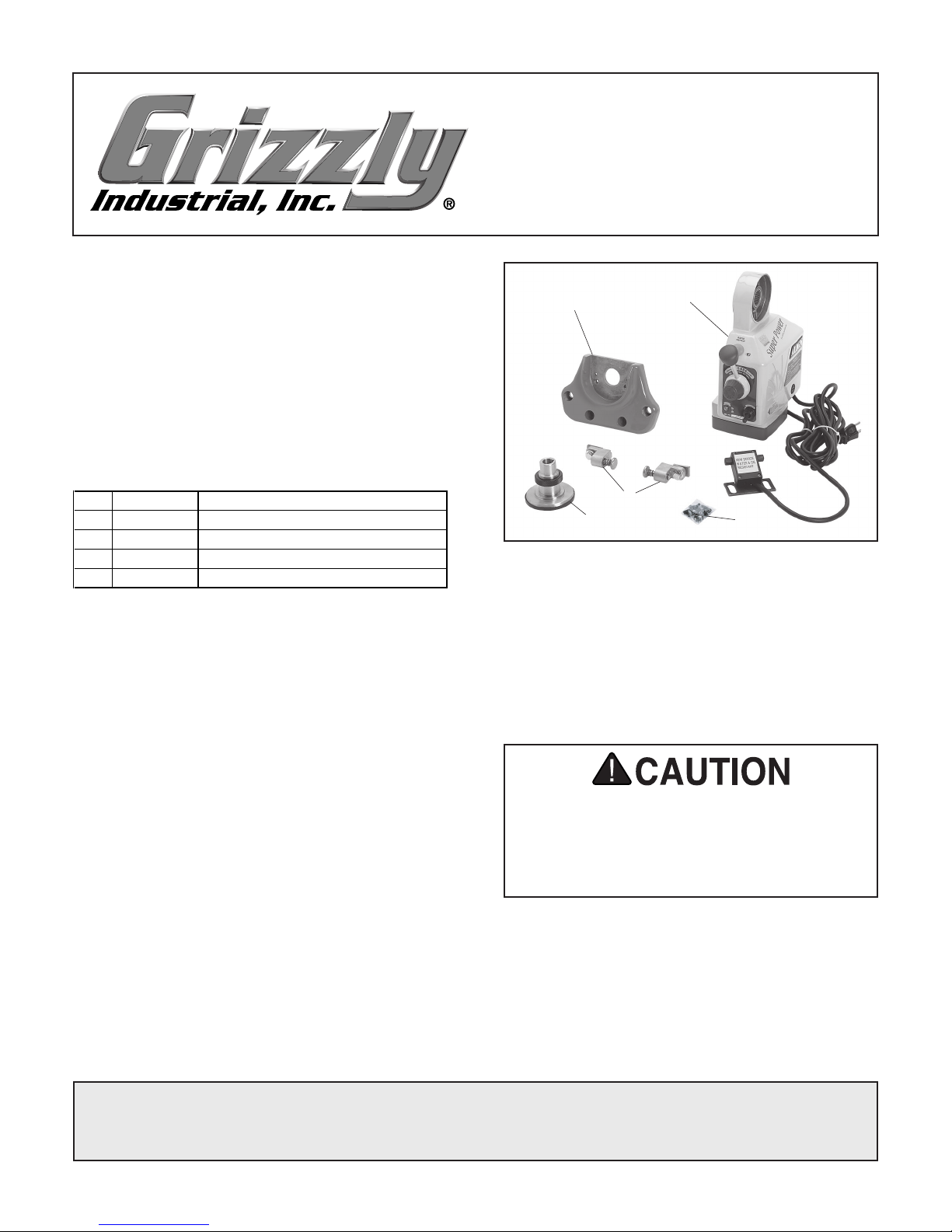
REF PART # DESCRIPTION
1 PH8371001 MOUNTING BRACKET
2 PH8371002 POWER FEED & LIMIT SWITCH ASSY
3 PH8371003 COMPLETE BOLT BAG
4 PH8371004 LIMIT STOP ASSEMBLY
5 PH8371005 BEVEL GEAR BRASS
Motor ................................................. 110V 60Hz
Speed ............................................... 4–160 RPM
Maximum Torque .................................650 in./lb.
Inventory
Refer to Figure 1 and the table below to inventory
the contents of the shipping box.
MODEL H8371
POWER FEED
FOR KNEE MILLS
INSTRUCTIONS
Figure 1. Model H8371 inventory.
Bolt Bag Inventory Qty
Spacer Set 34mm ..............................................
Spacer Set 16mm ..............................................
Bushing Spacer .................................................
Slotted Flat Washer ...........................................
1
Special Hex Nut
Cap Screws
⁄2"-20 ...................................... 1
1
⁄4"-20 x 1" ..................................... 2
Roll Pins 5.1 x 14mm ........................................
3
Phillips Head Screws #10-24 x
⁄8" .................... 2
Flat Washers 5mm ............................................
Cable Clamps ....................................................
Tie Wraps ..........................................................
If any nonproprietary parts are missing (e.g. a
washer or a spacer), we will gladly replace them;
1
or for the sake of expediency, replacements can
be obtained at your local hardware store.
1
1
1
If you need help with your new power feed, call
our Tech Support at: (570) 546-9663.
2
2
2
2
Be sure there is enough running clearance
between the table, spindle, vise/clamps, or
jigs before turning the power feed ON. Be
aware that all of these objects represent
potential pinch points.
COPYRIGHT © MARCH, 2008 BY GRIZZLY INDUSTRIAL, INC.
WARNING: NO PORTION OF THIS MANUAL MAY BE REPRODUCED IN ANY SHAPE
OR FORM WITHOUT THE WRITTEN APPROVAL OF GRIZZLY INDUSTRIAL, INC.
#TS10534 PRINTED IN TAIWAN

Functional Overview
The Model H8371 power feed is designed to
install on the right side of a knee mill table to pro
vide powered longitudinal movement of the table.
Refer to Figure
become familiar with the functional parts of the
power feed system.
Figure 2. Power feed system.
A. Limit Switch: Stops powered table move
ment when either limit stop presses a plunger
on the switch.
B. Limit Stop: Activates the limit switch. Secure
these devices along the table to set the range
of movement.
C. Rapid Movement Button: Moves the table
at the maximum speed in the direction select
ed.
2 and the descriptions below to
Installation
1. DISCONNECT THE MILL FROM POWER!
Note: During the next step, take care not to
misplace the leadscrew keys.
2. Remove the handle and graduated dial
assemblies from the right side of the longitu
dinal (X-axis) leadscrew.
3. Determine if there is adequate support on
the mill to mount the power feed unit onto the
leadscrew.
— If adequate mounting for the power feed
unit exists at the end of the leadscrew, you
do not need to use the optional mounting
bracket. Continue with Step 4
.
— If there is not adequate mounting for the
power feed unit, you will need to use the
provided mounting bracket. Proceed to
Using the Mounting Bracket on
Page 4.
-
4. Make sure the leadscrew is clean of debris
and oil, then slide the power feed unit onto
the leadscrew and up against the mill, as
shown in
Figure 3.
Cap Screws
-
-
D. Direction Lever: Starts, reverses, and stops
longitudinal table movement.
E. Speed Dial: Controls the speed that the table
moves—turn the dial clockwise to increase
the speed.
F. Reset Button: When a current over 3.5
amps passes through the unit for more than
10 seconds, the internal circuit switch will cut
the power to the unit. Investigate and resolve
any problems, then use this button to reset
the internal circuit switch.
G. ON/OFF Switch: The master power switch
for the power feed.
H. Power Lamp: Lights when the power feed is
turned ON.
-2-
Leadscrew
Keys
Spacers
Figure 3. Power feed unit mounted on the
leadscrew.
Note: Use the spacers provided where nec-
essary to ensure that the parts installed on
the leadscrew stay snug up against one
another.
H8371 Power Feed for Knee Mills
 Loading...