

MODEL H7582
JUNIOR ELECTRIC GUITAR KIT
MANUAL UPDATE
This update covers improvements to this guitar since the manual was originally printed. Keep this update
with your Owner's Manual for future reference. If you have questions, contact Tech Support at (570) 546-
9663 or by email at
manual, you can download a copy from www.grizzly.com.
techsupport@grizzly.com. If you cannot find the original copy of the H7582 owner's
Inventory (See Manual Page 4)
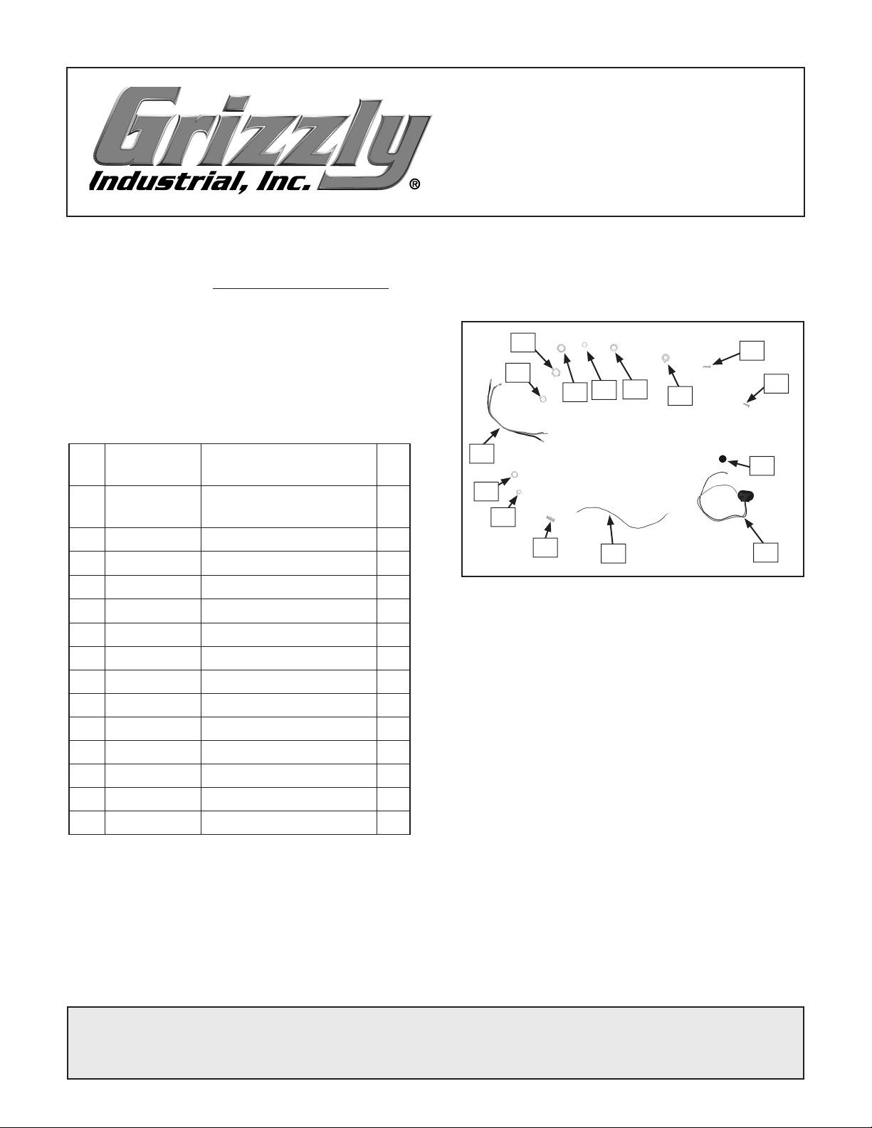
The following items have been revised or added
(see Figure
complete inventory.
REF PART # DESCRIPTION QTY
20 PH7582020 Chrome Plated Screw
24 PH7582024 Chrome Plated Screw
38 PH7582038 Felt Disc
39 PH7582039 Battery Terminal
40 PH7582040 Ground Wire 1
41 PH7582041 Compression Spring
42 PH7582042 Power Switch Nut
43 PH7582043 Special Washer 5mm
44 PH7582044 Output Jack Wire
45 PH7582045 Special Hex Nut
46 PH7582046 Output Jack Nut
47 PH7582047 Special Washer 7mm
48 PH7582048 Knurled Nut 6mm
49 PTLW13M Int. Tooth Washer 6mm
50 PH7582050 Special Washer
1). Refer to the full manual for the
2
#2 x 3/8"
2
#3 x 3/8"
2
1
2
1
1
1
2
1
2
1
1
1
44
43
46
45
49
48
47
42
41
Figure 1. Additional guitar parts.
40
50
20
24
38
39
Supplies/Tools (See Manual Page 5)
The following tools and supplies have been
added:
• Drill Bits:
• Aircraft Extension Bit:
3
⁄32", 1⁄16", 7⁄64"
7
⁄64"
Tuners (See Manual Page 9)
Follow Steps 1-3, then follow Step 4 below, which
has been revised:
4. Using a 1⁄16" bit, drill 3⁄8" deep holes through
the holes in the tuning head plate, and secure
with the #3 x
Figure 8
Note: Do not drill the holes deeper than 3⁄8"
or you could drill through the top of the head
stock.
COPYRIGHT © FEBRUARY, 2007 BY GRIZZLY INDUSTRIAL, INC.
WARNING: NO PORTION OF THIS MANUAL MAY BE REPRODUCED IN ANY SHAPE
OR FORM WITHOUT THE WRITTEN APPROVAL OF GRIZZLY INDUSTRIAL, INC.
#BL9007 PRINTED IN CHINA
3
⁄8" black screws as shown in
.
-
Neck (See Manual Page 10)
The following component has been revised.
Components Needed Qty
Chrome Plated Screws #7 x 1
Follow Step 1, then follow the revised steps
below.
2. Turn the guitar face down.
3. Insert a 3⁄32" drill bit through each of the neck
mounting holes and mark the pilot hole loca
tions.
1
⁄2" ...................... 1
Center Line
Mark
-
Figure 3. Marking center line.
4. Remove the neck, then drill 3⁄4" deep holes in
3
the neck. Do not drill deeper than
⁄4" or the
bit could go through the top of the fretboard.
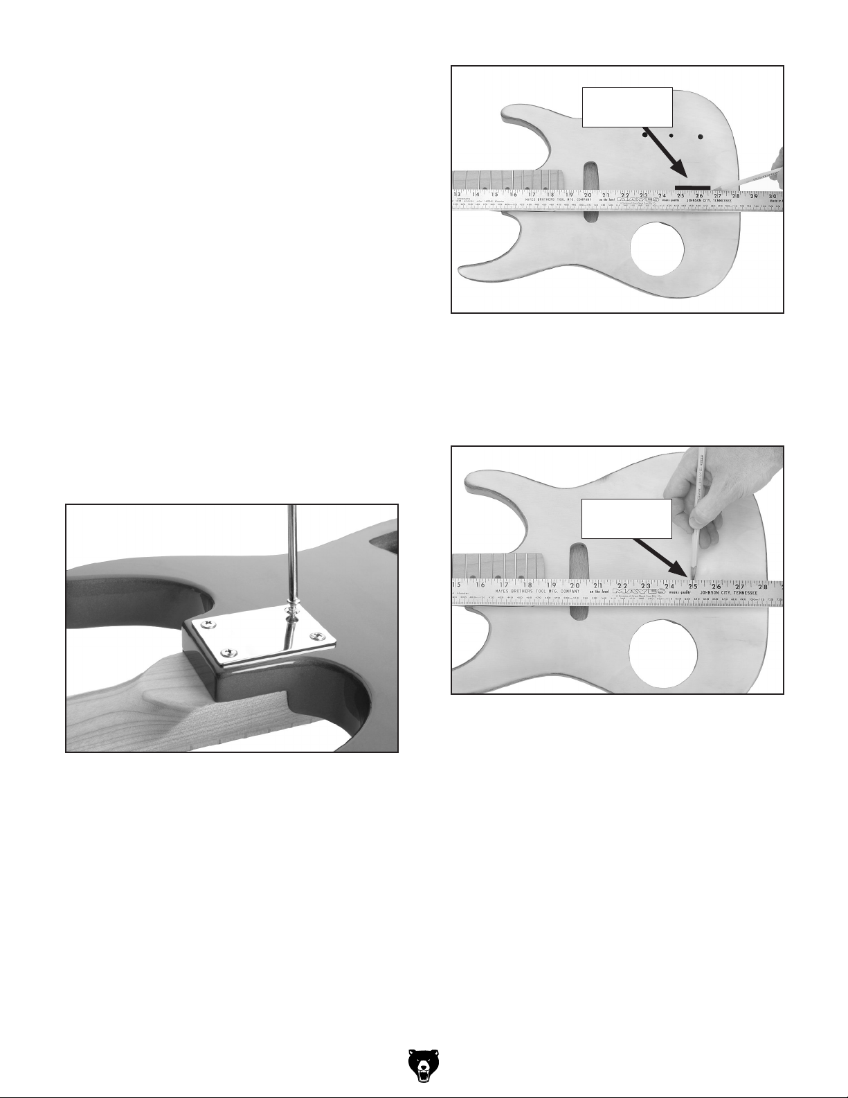
5. Place the neck in the neck pocket, place the
neckplate over the neck pocket holes, and
1
secure the neck to the guitar with #7 x 1
chrome plated screws as shown in
Figure 2.
/2"
7. Measure 251/16" from the fretboard side of the
nut to the right side of the body and draw a
vertical line as shown in
Figure 4. This line
will mark the neck-facing edge of the bridge.
Front of
Bridge Mark
Figure 4. Marking front of bridge.
Figure 2. Neckplate installation.
6. Turn the guitar face up and place a long
straightedge along the center of the fretboard
and mark the center line, as shown in
Figure
3.
Note: You may want to cover the marking
location with masking tape to avoid scratch
ing the finish.
-2-
-
H7582 Manual Update
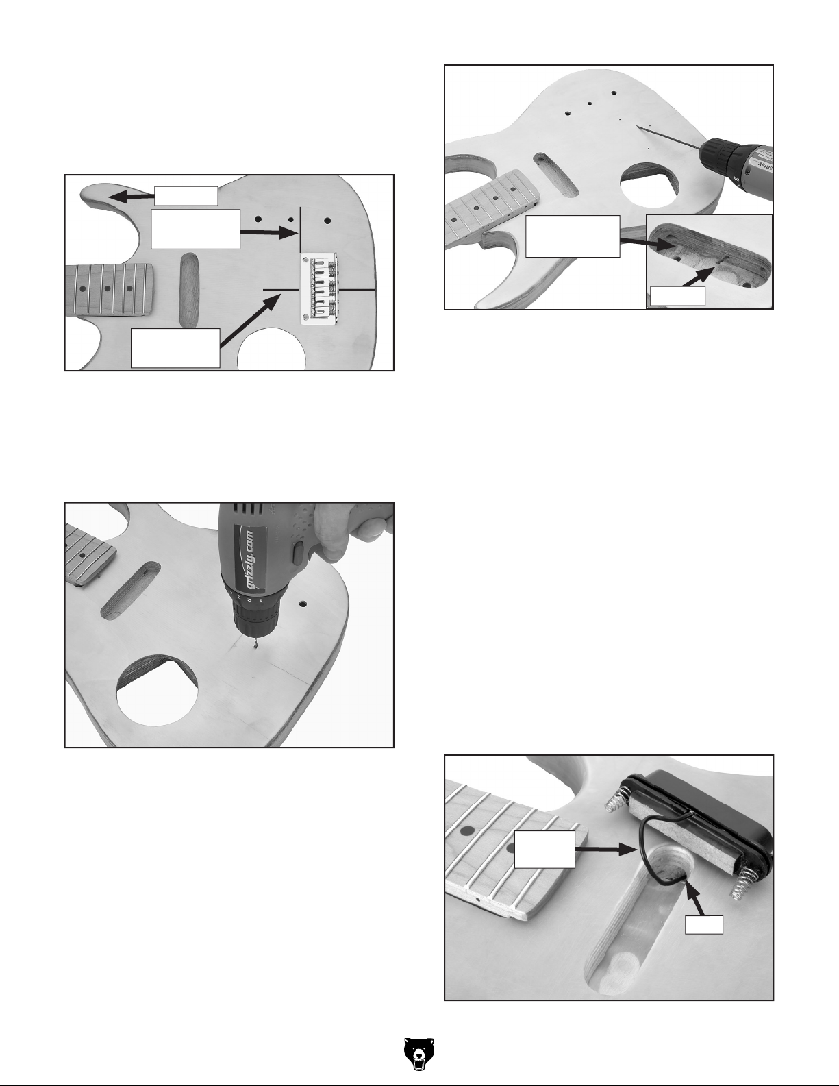
8. Place the bridge on the guitar so it is parallel
to the mark made in Step 7 and perpendicu
lar to the center line (see
FIgure 5). The center line should intersect the middle mounting
hole on the bridge.
To Neck
-
Front of
Bridge Mark
Center Line
Mark
Figure 5. Bridge placement location.
9. Mark the bridge mounting holes.
7
10. Using a
⁄64" bit, drill a
ground wire as shown in
1
⁄4" deep hole for the
Figure 6.
Circuit Board
Mortise
Drill Bit
Figure 7. Drilling bridge ground wire shaft into
circuit board mortise.
12. Insert the black ground wire through the hole
to check the fit, then remove the ground
wire.
Pickup (See Manual Page 11)
To install the pickup:
1. Place the guitar face-side up.
2. Place the #3 x 3/4" black screws through the
pickup, insert it into the pickup mortise, then
use the screw tips to mark the mounting
holes.
Figure 6. Drilling ground wire pilot hole.
7
11. Using a
⁄64" aircraft extension bit, drill a shaft
at a shallow angle toward the circuit board
mortise as shown in
Figure 7.
Note: If the shaft angle is not shallow enough,
you could drill through the back of the body.
3. Using a 1/16" bit, drill 1/2" deep holes for the
mounting holes.
4. Insert the pickup wire (Figure 8) through the
hole in the pickup mortise and into the circuit
board mortise.
Pickup
Wire
Hole
Figure 8. Pickup installation location.
H7582 Manual Update
-3-
5. Insert the pickup into the mortise, positioning
3
each #3 x
⁄4" black screw through a spring.
6. Secure the pickup to the guitar body with the
black screws. Be careful NOT to thread the
screws through the pickup wire.
7. Turn the guitar over so the back is face-side
up.
8. Solder the pickup wire onto the volume control as shown on the Wiring Diagram on
Page 8 of this Manual Update.
Speaker (See Manual Page 11)
To install the speaker:
Follow the revised steps below:
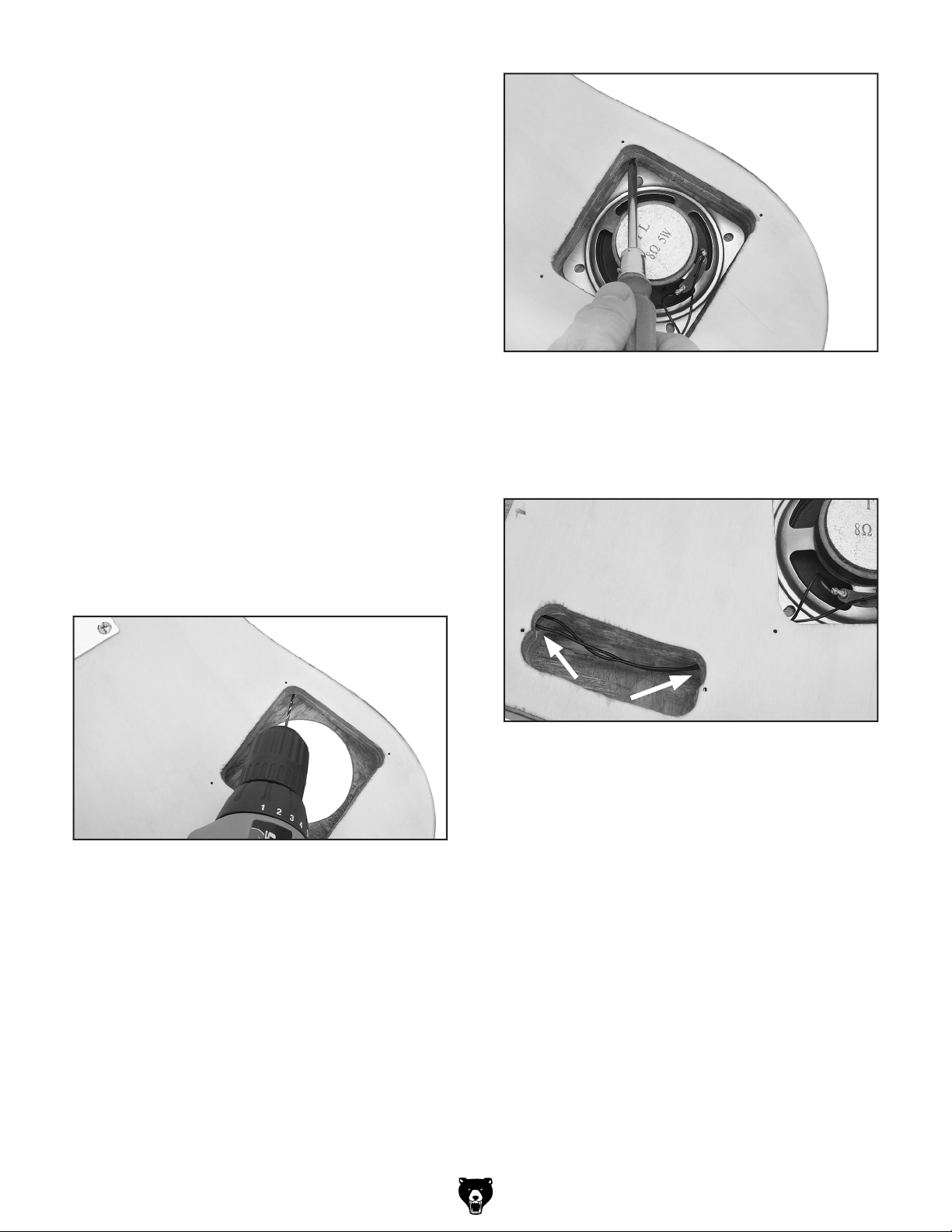
1. Place the speaker and mesh cover into the
bottom of the speaker mortise.
2. Using a 1⁄16" bit, drill four 1⁄8" deep holes at a
shallow angle slightly above the mesh cover
(see Figure 9).
Figure 9. Drilling speaker mounting holes.
3. Secure the speaker with four #2 x 1⁄4" black
screws (see Figure 10
screws are tight enough that the speaker will
not move.
). Make sure the
Figure 10. Fastening speaker with screws.
4. Insert the two black wires on the headphone
jack through holes in the circuit board and
battery case
mortises (Figure 11) and into
the speaker mortise.
Figure 11. Speaker wires in battery case
mortise.
5. Solder the wires onto the speaker as shown
on the Wiring Diagram on
Manual Update
.
Page 8 of this
6. Place the speaker cover on the guitar, mark
1
the four mounting holes and, using a
3
⁄16" deep holes.
drill
7. Secure the cover with #2 x
1
⁄4 black screws.
⁄16" bit,
-4-
H7582 Manual Update

Battery Case (See Manual Page 12)
To install the battery case:
1. Insert the battery case wires through the
plastic case, through the hole in the battery
case mortise, and into the circuit board mor
tise.
2. Slide the battery case (Figure 12) into the
mortise, drill holes for two #2 x
1
screws using a
1
⁄4" black screws.
#2 x
⁄16" bit, and secure with two
1
⁄4" black
2. Strip the included red and black output jack
wires as needed and solder onto the output
jack and volume control as shown on the
Wiring Diagram on
Page 8 of this Manual
Update.
-
3. Insert the headphone, AC/DC, and output
jacks through the mortise in the side of the
guitar, then through the jack plate (Figure
13).
AC/DC
Output
AC/DC
Headphone
Figure 12. Installing battery case.
Headphone, AC/DC & Output Jacks
(See Manual Page 12)
The following component has been revised.
Components Needed Qty
Output Jack .......................................................
Output Jack Wires .............................................
To install the headphone, AC/DC, and output
jacks:
1. Solder the battery case wires onto the AC/DC
jack.
1
1
Figure 13. Inserting jacks through jack plate.
4. Fasten the jacks to the plate with the included
nuts and washers.
5. Place the jack plate over the mortise, mark
1
the mounting holes, then using a
⁄16" bit, drill
holes inward at a slight angle toward the mor
tise.
14).
3
⁄8" #3
6. Secure the jack plate with the
chrome plated screws (see Figure
1
⁄2" and
-
H7582 Manual Update
Figure 14. Securing jack plate.
-5-

Volume, Tone, & Circuit Board (See
Manual Page 13)
The following component has been revised.
5. Thread the wire until it protrudes through the
top of the guitar body. Place a piece of mask
ing tape over the wire to hold it temporarily.
-
Components Needed Qty
Ground Wire ......................................................
To install the tone control, volume control and
power switch:
1. Solder the black and white circuit board wires
and the black ground wire onto the volume
control as shown on the Wiring Diagram on
Page 8 of this Update.
2. Insert the volume and tone controls through
the sockets on the guitar body as shown in
Figure 15.
1
6. Remove the hex nut and interior tooth washer
from the power switch.
7. Insert the power switch, which is mounted to
the circuit board, through the guitar body as
shown in
Figure 16. Installing power switch.
Figure 16.
Power Switch
Volume
Control
Tone
Control
Figure 15. Installing tone and volume controls.
3. Install the included nuts and washers onto
the volume and tone controls, then install the
volume and tone control knobs.
4. Insert the grounding wire through the hole
in the side of the circuit board mortise (see
Figure 7).
Note: It may help to use tweezers or pliers.
8. Re-install the hex nut and interior tooth wash-
er removed earlier
.
Circuit Board Cover (See Manual
Page 14)
The following component has been revised.
Components Needed Qty
Black Screws #2 x
To install the circuit board cover:
1. Place the circuit board cover over the circuit
board mortise (
holes, and drill pilot holes using a
1
⁄4" ...................................... 2
Figure 17), mark mounting
1
⁄16" bit.
-6-
H7582 Manual Update
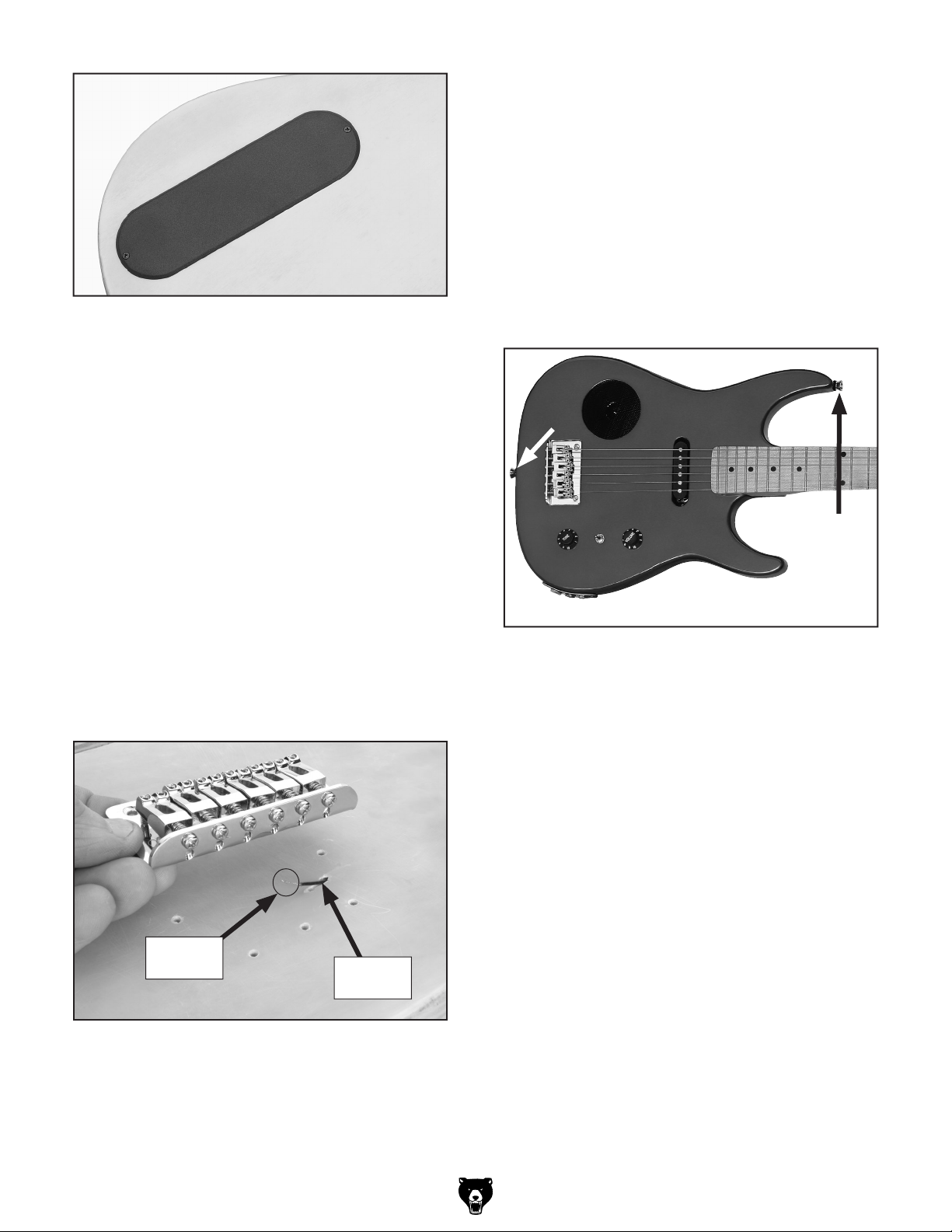
Figure 17. Circuit board cover installed.
1
2. Secure the cover with #2 x
⁄4" black screws.
Bridge (See Manual Page 14)
To attach the bridge to the guitar body:
1. Make sure the end of the grounding wire
(Figure 18) protrudes through the angled
hole (drilled earlier) to make contact with the
bridge.
Strap Button (See Manual Page 15)
The following component has been revised.
Components Needed Qty
Felt Buttons .......................................................
To attach the strap to the guitar:
1
1. Using a
tons in the locations shown in
secure each strap button with a felt disc and
a #4 x
⁄16" bit, drill holes for the strap but-
Figure 19, then
3
⁄4" chrome plated screw.
2
2. Secure the wire in the hole with rubber
cement, leaving the end exposed.
3. Using a
1
⁄16" bit, drill
3
⁄4" deep holes for the
bridge mounting holes.
3
4. Secure the bridge with five #4 x
⁄4" chrome
plated screws.
Exposed
Section
Ground
Wire
Figure 19. Strap buttons.
String Retainers (See Manual Page
16)
The following component has been revised.
Components Needed Qty
Chrome Plated Screws #2 x
3
⁄8" ........................ 2
Figure 18. Bridge placement.
H7582 Manual Update
-7-

Wiring Diagram (Manual Page 25)
The wiring diagram has been revised.
-8-
H7582 Manual Update

JUNIOR ELECTRIC GUITAR KIT
MODEL H7582
INSTRUCTION MANUAL
COPYRIGHT © AUGUST, 2005 BY GRIZZLY INDUSTRIAL, INC.
WARNING: NO PORTION OF THIS MANUAL MAY BE REPRODUCED IN ANY SHAPE
OR FORM WITHOUT THE WRITTEN APPROVAL OF GRIZZLY INDUSTRIAL, INC.
#BL7247 PRINTED IN CHINA


Table of Contents
SECTION 1: SAFETY ....................................................................................................................... 2
SECTION 2: INTRODUCTION .........................................................................................................
Foreword .................................................................................................................................... 3
Contact Info ................................................................................................................................
SECTION 3: PARTS INVENTORY ...................................................................................................
Inventory ..................................................................................................................................... 4
Supplies/Tools ............................................................................................................................ 5
Identification ............................................................................................................................... 6
SECTION 4:
Sanding the Body .......................................................................................................................
Finishing the
Tuners ........................................................................................................................................ 9
Neck ......................................................................................................................................... 10
Electronics ................................................................................................................................ 11
Covers ...................................................................................................................................... 14
Bridge ....................................................................................................................................... 14
Strap Button .............................................................................................................................
Winding Strings ........................................................................................................................
String Retainers .......................................................................................................................
SECTION 5: SET UP ......................................................................................................................
General ..................................................................................................................................... 17
Neck Adjustment ......................................................................................................................
String Height ............................................................................................................................
Pickup Height ...........................................................................................................................
Setting Intonation .....................................................................................................................
Tuning ...................................................................................................................................... 20
Basic Guitar Care .....................................................................................................................
SECTION 6: REFERENCE INFO ...................................................................................................
Accessories .............................................................................................................................. 21
Electrical Components .............................................................................................................
Electrical Components .............................................................................................................
Wiring Diagram ........................................................................................................................
WARRANTY AND RETURNS ........................................................................................................
ASSEMBLY ................................................................................................................. 7
Body ...................................................................................................................... 7
15
15
16
17
17
18
19
19
20
21
23
24
25
26
3
3
4
7

SECTION 1: SAFETY
Always wear safety glasses or goggles when operating equipment. Everyday glasses or reading glasses are not safety glasses. Be certain the safety glasses you wear meet the appropri
ate standards of the American National Standards Institute (ANSI).
Because there are various ways to cut and join wood, you can make substitutions for the methods
stated in this plan. We try to suggest the easiest methods possible. However, only you know your
skills with each piece of machinery. Never compromise your safety by using a cutting method
with which you are not comfortable. Instead, find an alternative approach that will yield the same
result.
These instructions assume that you are intimately familiar with the safe operation and use of
woodworking machinery and woodworking tools, and understand the techniques used to build this
project. If you do not qualify for both of these criteria, STOP building this project for your own
safety. Read and understand the owners manual for the machinery you intend to use, take a wood
working class or visit your local library for more information. Woodworking machinery and tools
are inherently dangerous because they use sharp edges that can and will cause serious personal
injury including amputation and death. Do not underestimate the ability of these tools and machin
ery to cause injury. Never operate any tool without all guards in place and always wear approved
safety glasses. For your own safety, please heed this warning.
-
-
-
-2-
Model H7582 Junior Electric Guitar Kit
 Loading...