

Page 1
COPYRIGHT © APRIL, 2003 BY GRIZZLY INDUSTRIAL, INC.
WARNING: NO PORTION OF THIS MANUAL MAY BE REPRODUCED IN ANY SHAPE
OR FORM WITHOUT THE WRITTEN APPROVAL OF GRIZZLY INDUSTRIAL, INC.
PRINTED IN CHINA
ONLINE MANUAL DISCLAIMER
THE INFORMATION IN THIS MANUAL REPRESENTS THE CONFIGURATION OF THE MACHINE
AS IT IS CURRENTLY BEING SHIPPED. THE MACHINE CONFIGURATION CAN CHANGE AS
PRODUCT IMPROVEMENTS ARE INCORPORATED. IF YOU OWN AN EARLIER VERSION OF
THE MACHINE, THIS MANUAL MAY NOT EXACTLY DEPICT YOUR MACHINE . CONTACT CUS-
TOMER SERVICE IF YOU HAVE ANY QUESTIONS ABOUT DIFFERENCES. PREVIOUS VER-
SIONS ARE NOT AVAILABLE ONLINE.
PANCAKE AND HOT DOG
AIR COMPRESSORS
MODEL H3370/H3371
INSTRUCTION MANUAL
Page 2

WARNING
Some dust created by power sanding, sawing, grinding, drilling, and other construction activities contains
chemicals known to the State of California to cause
cancer, birth defects or other reproductive harm.
Some examples of these chemicals are:
• Lead from lead-based paints.
• Crystalline silica from bricks, cement, and
other masonry products.
• Arsenic and chromium from chemically treated
lumber.
Your risk from these exposures varies, depending on
how often you do this type of work. To reduce your
exposure to these chemicals: work in a well ventilated
area, and work with approved safety equipment, such
as those dust masks that are specially designed to filter out microscopic particles.
Page 3
-1-Model H3370/H3371 Air Compressors
For Your Own Safety Read Instruction Manual
Before Operating This Equipment
Indicates an imminently hazardous situation which, if
not avoided, WILL
result in death or serious injury.
Indicates a potentially hazardous situation which, if
not avoided, COULD
result in death or serious injury.
Indicates a potentially hazardous situation which, if
not avoided, MAY
result in minor or moderate injury.
It may also be used to alert against unsafe practices.
This symbol is used to alert the user to useful infor-
mation about proper operation of the equipment.
The purpose of safety symbols is to attract your attention to possible hazardous
conditions. This manual uses a series of symbols and signal words which are
intended to convey the level of importance of the safety messages. The progression of symbols is described below. Remember that safety messages by themselves do not eliminate danger and are not a substitute for proper accident prevention measures.
NOTICE
Safety Instructions For Pneumatic Tools
1. KEEP ALL SAFETY DEVICES IN
PLACE and in working order.
2. REMOVE ADJUSTING KEYS AND
WRENCHES. Form a habit of
checking to see that keys and
adjusting wrenches are removed
from tool before operation.
3. KEEP WORK AREA CLEAN.
Cluttered areas and benches invite
accidents.
4. DO NOT USE IN DANGEROUS
ENVIRONMENT. DO NOT use
pneumatic tools in damp or wet
locations, or where any flammable
or noxious fumes may exist. Keep
work area well lighted.
SAFETY
5. KEEP CHILDREN AND VISITORS
AWAY. All children and visitors
should be kept at a safe distance
from work area.
6. MAKE WORKSHOP CHILD
PROOF with padlocks, master
switches, or by removing air hoses
from tools.
7. DO NOT FORCE TOOL. It will do
the job better and safer at the rate
for which it was designed.
8. USE THE RIGHT TOOL. DO NOT
force tool or attachment to do a job
for which it was not designed.
9. DO NOT USE UNDER THE INFLUENCE OF DRUGS OR ALCOHOL.
Page 4

Model H3370/H3371Air Compressors-2-
10. USE PROPER AIR HOSE for the
tool. Make sure your air hose is in
good condition and is long enough to
reach your work without stretching.
11. WEAR PROPER APPAREL. DO
NOT wear loose clothing, gloves,
neckties, rings, bracelets, or other
jewelry which may get caught in
moving parts. Non-slip footwear is
recommended. Wear a protective
hair covering to contain long hair.
12. ALWAYS USE SAFETY GLASSES.
Also use a face or dust mask if cutting operation is dusty. Everyday
eyeglasses only have impact resistant lenses, they are NOT safety
glasses.
13. WEAR APPROVED HEARING
PROTECTION.
14. NEVER USE PLASTIC (PVC) PIPE
FOR COMPRESSED AIR. Serious
injury could result.
16. MAINTAIN TOOLS WITH CARE.
Keep tools lubricated and clean for
best and safest performance. Follow
instructions for lubricating and
changing accessories.
17. REDUCE THE RISK OF UNINTENTIONAL STARTING. DO NOT carry
tool with hand on trigger and always
disconnect from air when not in use.
18. DISCONNECT TOOLS before servicing and changing accessories.
Safety Instructions For Pneumatic Tools
19. USE THE RECOMMENDED
ACCESSORIES. Consult the
owner’s manual for recommended
accessories. The use of improper
accessories may cause risk of
injury.
20. CHECK DAMAGED PARTS.
Before further use of the tool, a
guard or other part that is damaged
should be carefully checked to
determine that it will operate properly and perform its intended function. Check for alignment of moving
parts, binding of moving parts,
breakage of parts, mounting, and
any other conditions that may affect
its operation. A guard or other part
that is damaged should be properly
repaired or replaced.
21. NEVER LEAVE UNATTENDED
TOOL CONNECTED TO AIR.
Disconnect the air hose and DO
NOT leave tool until it is relieved of
any built up pressure.
22. NEVER ALLOW UNTRAINED
USERS TO USE THIS TOOL
WHILE UNSUPERVISED.
23. IF YOU ARE UNSURE OF THE
INTENDED OPERATION, STOP
USING THE TOOL. Seek formal
training or research books or magazines that specialize in pneumatic
tools.
Page 5
Model H3370/H3371Air Compressors -3-
1. READ THIS ENTIRE MANUAL
BEFORE OPERATING THE
COMPRESSOR.
2. OPERATE THE COMPRESSOR IN
A WELL VENTILATED AREA free
of acids, vapor, explosive gases and
flammable or unstable materials.
3. DO NOT PULL ON THE GAUGES
OR REGULATORS TO MOVE THE
COMPRESSOR!
4. DO NOT USE THE COMPRESSOR
FOR FILLING BREATHING OR DIVING APPARATUS. Compressed air
from this compressor cannot be used
for pharmaceutical, food or health
requirements without further treatment.
5. NEVER TRANSPORT THE COMPRESSOR UNDER PRESSURE.
Always release the pressure in the
storage tanks before moving.
6. NEVER RUN THE COMPRESSOR
BEYOND THE ADVISED DUTY
CYCLE!
Additional Safety For
Air
Compressors
7. DRAIN TANK DAILY OR AT THE
END OF EACH USE to avoid tank
corrosion and possible tank rupture.
8. AVOID TOUCHING THE TOP OF
THE MOTOR HOUSING, it will
become hot during operation.
9. MAKE SURE TO ADD OIL! Use
compressor oil or a non-detergent 30
weight oil.
10. NEVER LEAVE COMPRESSOR
TURNED ON WHEN NO ONE IS
AROUND! A leak could develop caus-
ing compressor to run continuously
causing overheating and possibly a
fire.
11. NEVER AIM THE AIR NOZZLE
DIRECTLY AT YOURSELF OR OTHERS. Pressurized air can break or
bruise the skin.
12. NEVER LOAD YOUR COMPRESSOR PAST THE MAXIMUM PSI
RATING!
Operating this compressor can propel objects into the air, causing
immediate eye damage. To protect
yourself, always wear American
National Standards Institute (ANSI)
approved safety glasses or goggles
when operating this equipment.
NOTICE
Always be aware of the duty cycle
for your air compressor. Failure to
operate the air compressor properly
could result in overheating and
motor seizure. There could also be
risk of fire hazard due to overheating. Be sure to use a compressor
capable of handling the air demand
of connected tools
Page 6
Model H3370/H3371Air Compressors
INTRODUCTION AND SET UP
If you have any comments regarding this
manual, please write to us at the following
address:
Grizzly Industrial, Inc.
C
/O Technical Documentation
P.O. Box 2069 Bellingham, WA 98227-
2069
Most important, we stand behind our tools.
If you have any service questions or parts
requests, please call or write us at the
location listed below.
Grizzly Industrial, Inc.
1203 Lycoming Mall Circle
Muncy, PA 17756
Phone: (570) 546-9663
Fax: (800) 438-5901
E-Mail: techsupport@grizzly.com
Web Site: http://www.grizzly.com
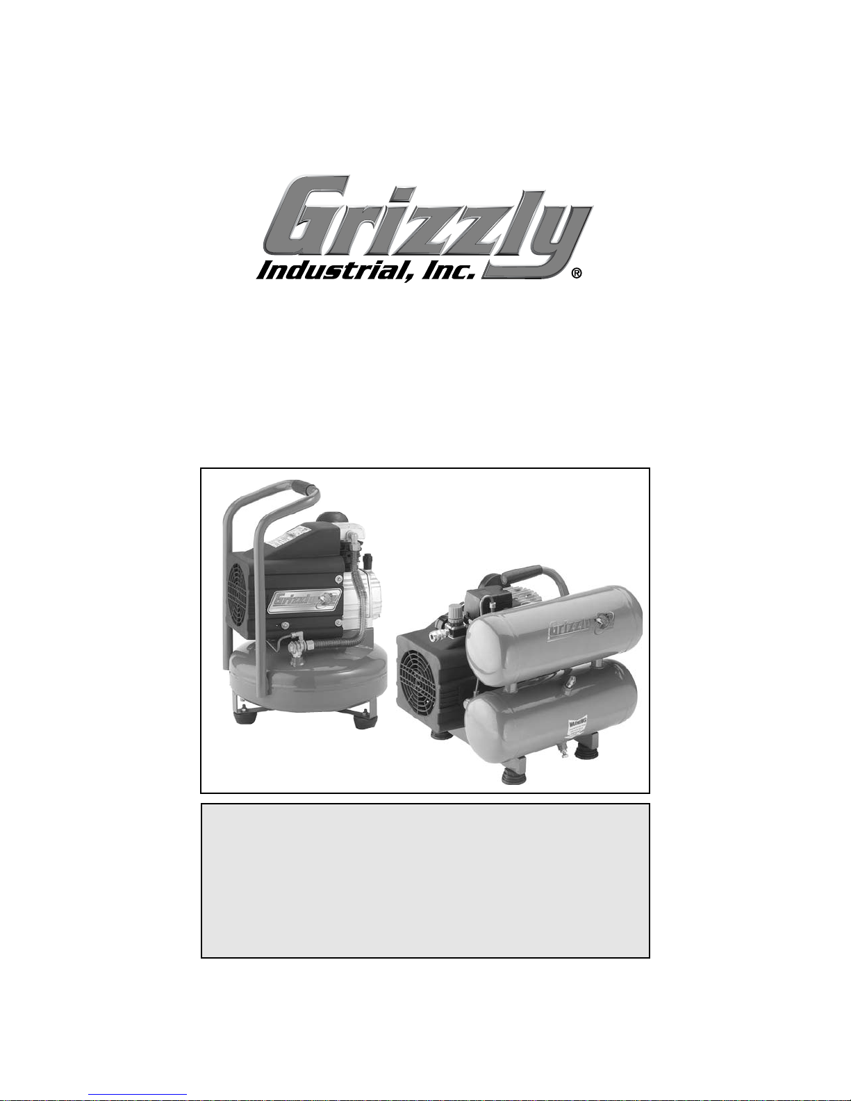
We are proud to offer the Grizzly Model
H3370 Pancake and H3371 Hot Dog AIr
Compressors. These models are part of a
growing Grizzly family of fine power tools.
When used according to the guidelines set
forth in this manual, you can expect years
of trouble-free, enjoyable operation and
proof of Grizzly’s commitment to customer
satisfaction.
The Model H3370 features a 2.5 HP
motor, a cast iron direct drive pump, 4 gallon tank capacity that delivers 4.6 CFM
@90 PSI and 5.9 CFM @40 PSI, and is oil
lubricated. The H3370 has a maximum PSI
rating of 115.
The Model H3371 features a 2.5 HP
motor, a cast iron direct drive pump, two 2
gallon tanks that deliver 4.6 CFM @90 PSI
and 5.9 CFM @40 PSI, and is oil lubricated. The H3371 has a maximum 115 PSI
rating.
We are pleased to provide this manual
with the Model H3370 and H3371. It was
written to encourage safety considerations
and guide you through general operating
procedures and maintenance. This manual represents our effort to produce the best
documentation possible.
The specifications, details, and photographs in this manual represent the
Model H3370/H3371 as supplied when the
manual was prepared. However, owing to
Grizzly’s policy of continuous improvement, changes may be made at any time
with no obligation on the part of Grizzly.
Read the manual before assembly
and operation. Become familiar with
this machine, its safety instructions,
and its operation before beginning
any work. Serious personal injury
may result if safety or operational
information is not understood or followed.
-4-
Commentary
Page 7
Model H3370/H3371Air Compressors
-5-
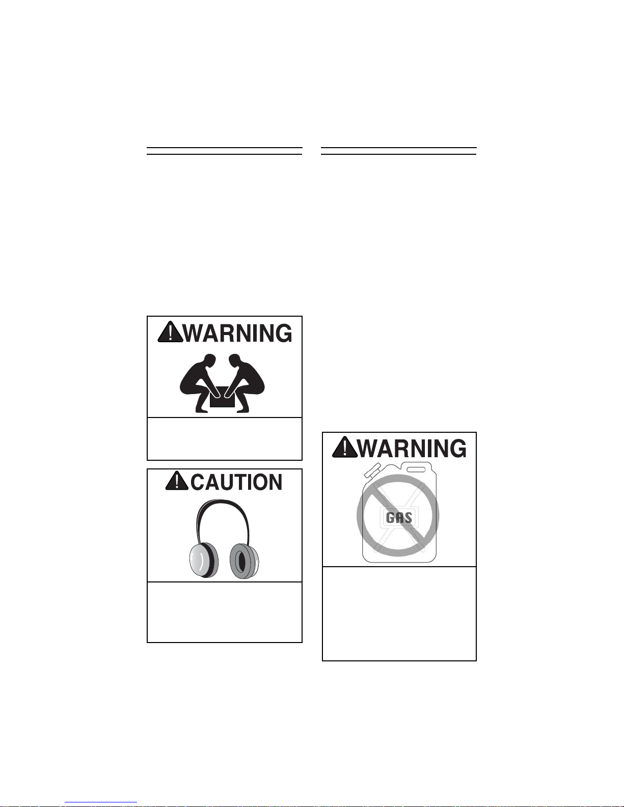
The Model H3370/H3371 represents
a heavy load at 60 pounds. Seek
assistance before moving.
This air compressor is shipped from the
manufacturer in a carefully packed carton.
If you discover the machine is damaged
after you have signed for delivery, and the
truck and driver are gone, you will need to
file a freight claim with the carrier. Save the
containers and all packing materials for
possible inspection by the carrier or its
agent. Without the packing materials, filing
a freight claim can be difficult. If you need
assistance determining whether you need
to file a freight claim, or with the procedure
to file one, please contact our Customer
Service at (570) 546-9663.
When determining where to set up the air
compressor in the shop or when taking the
air compressor to a job site, the most
important consideration is access to an
adequate and properly fused power supply. Refer to Circuit Requirements for the
needs of your particular compressor.
Also, make sure the compressor is not
operating in an environment where there
are any explosive, flammable or caustic
fumes or gases. A clear and well ventilated area is best for its safe operation.
Place the compressor on a solid and level
surface. Make sure that the hoses you
attach to your pneumatic device will be
unrestricted in movement and not subject
to being run over by vehicles or punctured
by any sharp objects in the area.
Since air compressors are often used for a
sustained period of time, sometimes in
restricted areas, it is also best to wear ear
protection to avoid long term exposure to
the sound of the electric motor and piston.
Long term exposure to this machine
may cause hearing loss. Wear
approved hearing protection while
operating this machine to minimize
this risk!
Unpacking
Site Placement
Do not place the compressor next to
any flammable liquids or gas! The
compressor cylinder head and feed
pipe can reach high temperatures and
could cause the flammable gas to
ignite. Keep work area clear from
flammable gas when using the compressor.
Page 8
Model H3370/H3371Air Compressors-6-
CIRCUIT REQUIREMENTS
The Model H3370/H3371 Air Compressor
is wired for 110/120V, single-phase operation only. The maximum amperage draw
for the machine is 17 amps, with a fusing
level rating of 20 amps.
It is best to operate a compressor on a
dedicated circuit, i.e. a circuit where there
are no other electrical appliances plugged
in. The fuse requirements above assume
the use of a circuit breaker or a slow-blow
fuse. If an unusual load does not exist and
the compressor still breaks the circuit, contact a qualified electrician or our service
department at (570) 546-9663.
110V Operation
Extension Cords
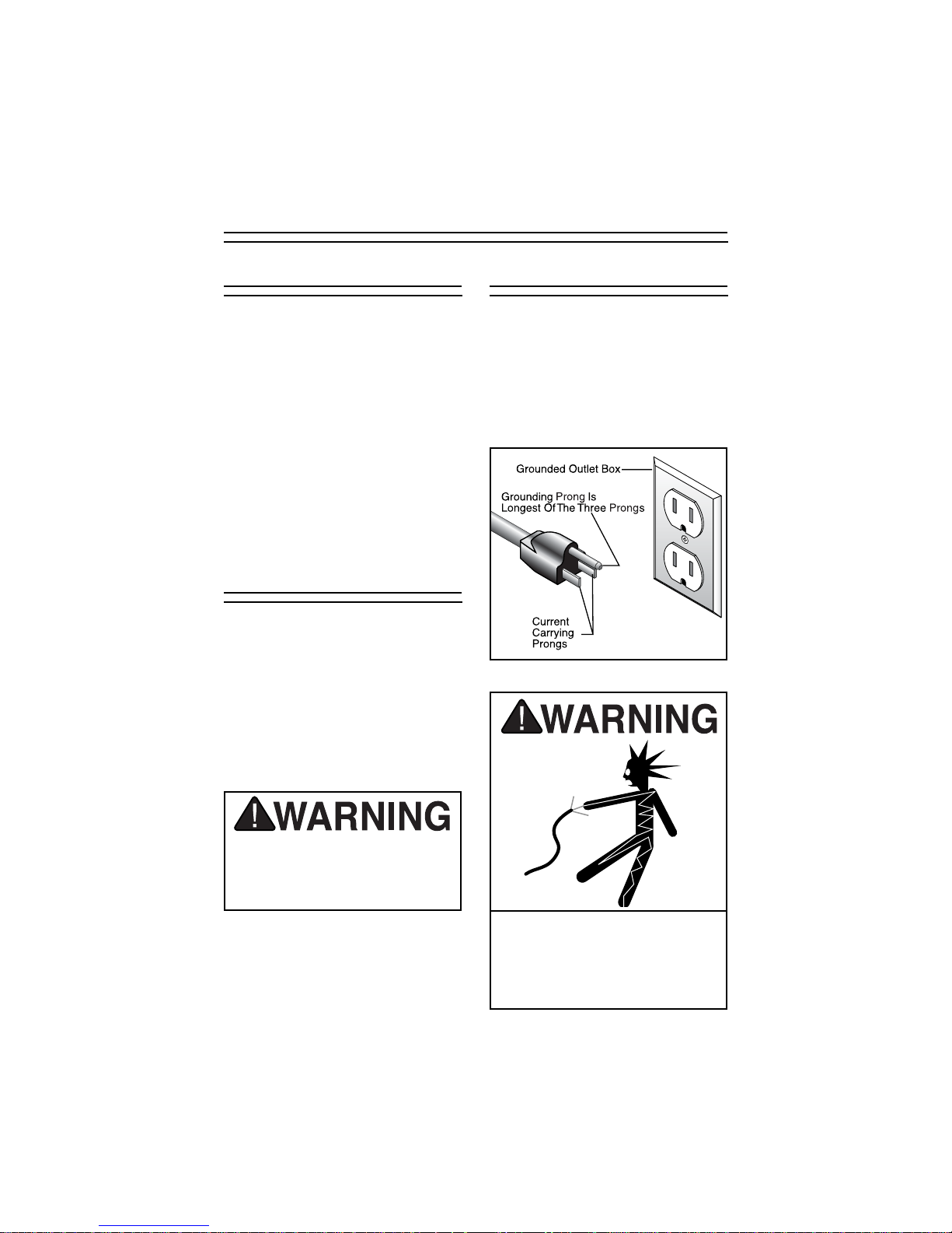
In the event of an electrical short, grounding reduces the risk of electric shock by
providing a path of least resistance to disperse electric current. These machines are
equipped with power cords having an
equipment-grounding conductor. See
Figure 1. The outlet must be properly
installed and grounded in accordance with
all local codes and ordinances.
Grounding
Figure 1. Ground plug configuration.
If you find it necessary to use an extension
cord with your compressor, make sure the
cord is rated Standard Service (grade S) or
better. Refer to the chart in the standard
safety instructions to determine the minimum gauge for the extension cord. The
extension cord must also contain a ground
wire and plug pin. Always repair or replace
extension cords when they become worn
or damaged.
Overheating, short circuit and fire
damage will result from inadequate
wiring. Follow the guidelines in this
section.
Potential for electrical shock hazard,
this equipment must be grounded.
Verify that any existing electrical
outlet and circuit you use is actually
grounded.
Page 9
Model H3370/H3371Air Compressors -7-
PREPARING FOR USE
Before using your Grizzly Air
Compressor, follow these steps:
1. Remove all packing materials and any
protective plastic bags, zip tie labels
or tags from the compressor.
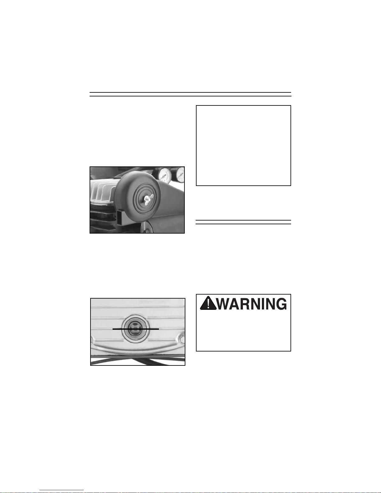
2. Be sure the air filter is attached to the
cylinder head as shown in Figure 2.
Figure 3.
Proper oil level.
4. Make sure the drain valve on the air
tank is closed.
3. ADD OIL TO THE CRANKCASE. Oil
has been supplied with your air compressor. Remove the oil breather on
top of the crankcase and add oil into
the hole. The oil level should be in the
center of the sight gauge shown in
Figure 3.
NOTICE
The machine should never be run
without a full oil reservoir. The oil
provides lubrication to the cylinder
rings which deliver the compressed
air. Severe damage to the internal
moving parts can occur if there is
not adequate oil flow. Check the oil
level frequently, and change the oil
every 3 months.
Figure 2. Air filter attached to
cylinder hear.
Duty Cycle
5. Know and understand the duty cycle
of the compressor before operating.
Overheating, short circuit and fire
damage will result form operating
beyond the recommended duty
cycle. Severe injury and property
damage could occur.
The Model H3370/H3371 Air Compressor
should NOT be operated on more than a
50% duty cycle. (This means an air compressor that pumps air for over 30 minutes
in one hour is considered misuse. This
could mean that the air compressor is
undersized for the required air demand.
Note—The maximum compressor pump
time per hour is 30 minutes.
Page 10

Model H3370/H3371Air Compressors-8-
STARTING
To start the air compressor:
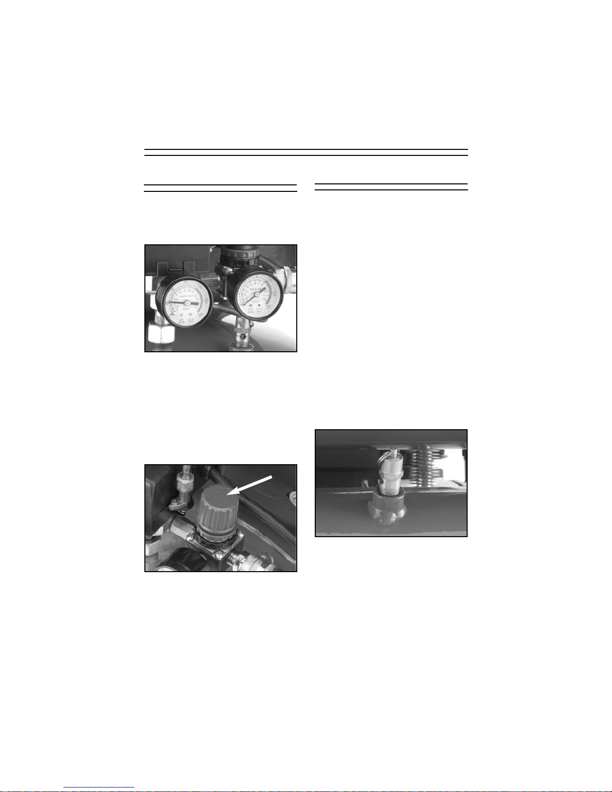
1. Make sure the compressor switch is in
the OFF position (lever with red cap
above pressure gauges shown in
Figure 4) before connecting to the
power supply.
Figure 4. ON/OFF lever.
Check the pressure gauge to see that the
tank pressure climbs to approximately 100115 PSI or around 8 BAR, then automatically turns off.
Note—If the compressor does not auto-
matically kick off, flip the ON/OFF switch to
OFF before pressure gets too high. See
the Pressure Regulator section.
Operating this equipment has the
potential for flying debris to cause
eye injury. Always wear safety glasses or goggles when operating equipment. Everyday glasses or reading
glasses only have impact resistant
lenses, they are not safety glasses.
Be certain the safety glasses you
wear meet the appropriate standards
of the American National Standards
Institute (ANSI).
2. Close the drain valve, shown in
Figure 5, so the tank can build up
pressure.
3. Double check the oil level to make
sure it is at the proper height.
4. Connect the compressor to the power
supply.
5. Flip the switch to the ON position
(where it reads AUTO).
Figure 5. Drain valve location.
Page 11
Model H3370/H3371Air Compressors -9-
To control the air delivery to your tool:
1. Adjust the air control knob, shown in
Figure 7, to set the PSI that will be
delivered to your tool. Turn the knob
clockwise to increase the pressure
and counter-clockwise to decrease
the pressure.
Figure 7. Air control knob.
Figure 6. Pressure gauges.
The tank pressure is displayed on the left
pressure gauge, and the air to be delivered
to the tool is displayed on the right pressure gauge shown in Figure 6.
AIR CONTROL
Delivered Pressure
Figure 8. Safety drain valve.
There are two ways to release air from the
compressor tank other than through your
regulator and the use of air tools:
—The drain valve
—The safety drain valve
To release air by using the drain valve, you
simply turn the release nut to allow air to
flow out of the tank. The drain valve is
shown in Figure 5. The drain valve is also
used to drain condensation that builds up
in the tank.
The safety valve automatically releases
pressure if the tank reaches 130 PSI.
To manually release the air in the tank
by using the safety drain valve:
1. Locate the safety drain valve on the
tank. The drain valve is shown below
in Figure 8.
Air Release
2. Pull the metal ring on top of the safe-
ty valve to bleed pressure from the
tank. Note—The ring is preset to
release air if the tank exceeds its
maximum pressure. DO NOT try to
adjust the safety valves pressure setting!
Note—The air tool that you attach to the air
compressor should have a preferred PSI
operating level. Set the pressure to be
delivered to the tool according to the tools
preferred level. Understand the duty
cycle of the air compressor.
Page 12

Model H3370/H3371Air Compressors-10-
The pressure regulator has been factory
set for the highest quality operating performance.
The pressure regulator sets the turn off
PSI setting for the air compressor tank.
Tank Pressure
Regulator
Figure 9. Pressure Regulator
To adjust the pressure regulator:
1. Unplug the air compressor from
the power supply.
2. Make sure the compressor switch is in
the OFF position.
3. Drain the pressure from the tank.
4. Remove the black ON/OFF switch
cover by removing the screw which is
in the recess on the top of the cover.
Pull the black cover up and set it
aside.
5. Turn the pressure adjustment screw
(Figure 9) a half turn clockwise to
increase the tank pressure and a half
turn counter-clockwise to decrease
the pressure.
6. Connect the compressor to the power
supply and start compressor.
7. If the PSI level still needs adjustment,
repeat steps 1 through 6.
8. Replace the cover when the proper
adjustments have been made.
NOTICE
The Model H3370/H3371 Air
Compressors have been factory set
to kick off at the proper PSI range.
Only attempt to adjust the pressure
regulator if your air compressor
does not reach or pressurizes
beyond the proper PSI level.
Page 13

Model H3370/H3371Air Compressors -11-
To connect air tools to your air compressor:
1. Make sure the compressor model you
use has a sufficient cubic feet per
minute (CFM) output for the air tool
you plan to connect. (Most air tools
will have an air requirement stated in
terms of a specific CFM at a specific
pressure.)
2. The compressor should put out a
higher CFM than the tool requires.
If you are connecting multiple tools
that will be used simultaneously, then
the CFM for each tool should be
added together and compared to the
compressor output value.
Consideration should also be given to the
type of usage. A nailer or staple gun uses
air in short bursts and it is easier for the
compressor to maintain pressure. A paint
sprayer or grinder tends to use a more
continuous stream of air as these tools are
run for longer time periods. It is always
better to oversize a compressor to allow
for variation in the type of usage and the
number of tools to be powered. Air tools
being operated with insufficient air volume
will not perform their function satisfactorily.
Figure 10. Quick connect couplers
3. Connect the tool, using a good quality
air line with an adequate length to
reach from the compressor to the
point of use.
Note—Quick-connect couplers, shown in
Figure 10, are a good option for fast and
sure connection of tools and air hoses.
CONNECTING TOOLS
Always disconnect air hose from
tools whenever not in use or while
servicing! During maintenance, a
tool connected to air may operate
accidentally, causing serious personal injury!
These couplers are included with the air
compressor. Make certain the air hose will
not be placed in a position where it can
become constricted or cut by a sharp
object. Note—Running over a hose with
heavy vehicles may not cause an immediate leak, but it will shorten the life of the
hose.
The Model H3370/H3371 Air
Compressors are specifically
designed for air tool operation. DO
NOT MODIFY OR USE THIS
MACHINE FOR ANY OTHER PURPOSE. Modifications or improper
use of this tool will void the warranty. If you are confused about any
aspect of this machine, DO NOT use
it until you have answered all your
questions. Serious personal injury
may occur.
Page 14

Model H3370/H3371Air Compressors-12-
MAINTENANCE
3. Clean off the cylinder head cooling
fins. Dirt interferes with heat transfer.
4. Check for worn or damaged cords
and plugs.
5. Check for any other condition that
could hamper the safe operation of
this machine.
6. Check the safety drain valve to make
sure it is working properly.
Each Use
Regular periodic maintenance on your
air compressor will ensure its optimum
performance. Make a habit of inspecting your compressor each time you use
it. Check the following items:
1. Check Oil Level! Use the sight gauge
on the bottom of the crankcase to
make sure the oil level is at the proper height.
2. Drain tanks daily of any condensation
by opening the drain valve on the bottom of the tank and leave open until
the next time it is used.
Depending upon the amount of use and
the surrounding humidity, a certain amount
of condensed water may accumulate in the
tanks. For longevity of the compressor
seals and the air tools you connect, it is
best to drain water from the tanks. The
tanks are best drained if the drain valve is
open when the system is pressurized.
Always wear safety glasses and use
extreme caution when working
around compressed air. The force of
the air stream can cause small bits
of debris to become airborne and
cause potential injury to the eyes or
other parts of the body. Never let the
full force of the air stream come in
direct contact with the skin as it can
cause abrasions or bruising, penetration of skin and could even lead
to death!
Always drain the air from the tank
before performing any maintenance
or transporting your air compressor.
Damage to the air compressor while
under pressure could cause bursting or explosion and injury or property damage could occur.
The air compressor will cycle automatically when it is on. When performing any type of maintenance
always make sure the AUTO/OFF
lever is in the OFF position the unit
is unplugged and bleed out all tank
pressure.
Page 15

Model H3370/H3371Air Compressors -13-
After First 50
Hours of Use
After the first 50 working hours or 30
days, whichever comes first, the following maintenance should be done.
1. Replace the oil in the motor with com-
pressor oil or use ISO 100 or SAE
30W viscosity, non detergent type oil.
2. Check to make sure that all the fittings
are tight.
3. Remove the air filter foam element
shown in Figure 11 and rinse it out
with water. Allow it to dry and reinstall.
Figure 11. Air filter foam element
4. Blow out any dirt that has accumulat-
ed between the cylinder cooling fans.
If the compressor is used on a daily
basis, perform the following checks
each week.
1. Rinse the air filter foam element in
water.
2. Check for loose bolts or fittings.
3. Clean off all foreign material from
cylinder head, motor, fan, air lines,
exhaust pipe, couplers and frame.
4. Check air lines and connectors to
make sure they are in good condition.
Weekly
Page 16

Model H3370/H3371Air Compressors-14-
After every 300 hours or 3 months of
regular operation, perform the following
maintenance items:
1. Change the compressor motor oil.
2. Rinse the air filter foam element in
water.
3. Check for air leaks and correct as
needed.
4. Clean the cylinder head fins for prop-
er cooling.
5. Check for loose bolts or fittings.
When storing your air compressor, follow these guidelines:
1. Set the compressor switch lever to
OFF.
2. Turn the regulator counter-clockwise
to set the delivery pressure to zero.
3. Remove the air tool or accessory.
4. Pull the safety drain valve ring to
bleed excess pressure from tank. The
pressure gauge for the tank should
read 15-20 PSI.
5. Drain water from the tank by opening
the drain valve on the bottom of the
tank.
6. Close the drain valve when all the
water has been released.
7. Store air compressor in its normal
operating position in a cool protected
area.
Every 300 Hours Storage
Like all power tools, there is danger
associated with operating this
equipment. Accidents are frequently
caused by lack of familiarity or failure to pay attention. Use this
machine with respect and caution to
lessen the possibility of operator
injury. If normal safety precautions
are overlooked or ignored, serious
personal injury many occur.
Water will condense in the air com-
pressor tank. Water left in the tank
can cause the tank to weaken and
corrode, increasing the risk of tank
rupture
Page 17

-15-Model H3370/H3371Air Compressors
TROUBLESHOOTING
Pump motor
will not start
Pump motor
starts; but
fuses blow or
circuit breakers trip.
Low pressure
at the tool
Low pressure
at the tanks
Compressor
knocking
Motor runs hot
1. Check power line for proper voltage.
2. Inspect all lead connections on motor,
switch and cord for loose or open connections.
3. Motor will not start if tank pressure is too
high.
4. Thermal overload switch has tripped, wait
for motor to cool, then reset switch by
pressing red button.
1. Inspect cord or plug for damaged insulation and shorted wires.
2. Inspect all connections on motor for loose
or shorted terminals or worn insulation.
3. Install correct fuses or circuit breakers.
1. Check air hoses and all connections for
leaks.
2. Check pressure in line with known good
gauge.
3. Adjust pressure regulator, if no improvement inspect regulator for leaks or
replacement.
1. Check air tanks, pipes and all connections
for leaks.
2. Close drain valve.
3. Replace safety valve.
4. Inspect and clean air filter.
5. Check gaskets on cylinder head assembly, repair or replace as needed.
6. Inspect and replace pump piston rings.
1. Check oil level and add oil.
2. Inspect and clean air filter.
3. Inspect and repair piston and connecting
rod.
1. Clean cylinder fins and motor area.
2. Inspect and clean air filter.
PROBLEM
CAUSE
ACTION
1. Low voltage.
2. Open circuit in
motor, switch or
cord.
3. Tank already pressurized.
4. Thermal overload
switch.
1. Short circuit in line
cord or plug.
2. Short circuit in motor
or loose connections.
3. Incorrect fuses or
circuit breakers in
power line.
1. Air leaks in flexible
hoses.
2. Pressure gauge bad.
3. Pressure regulator
bad.
1. Air leaks in tanks or
delivery pipes.
2. Drain valve open.
3. Safety valve releasing below 125 PSI.
4. Air filter clogged.
5. Gaskets leaking.
6. Worn rings.
1. Improper oil level.
2. Air filter clogged.
3. Piston assembly
loose.
1. Cooling fins dirty.
2. Air filter clogged.
Page 18

Model H3370/H3371Air Compressors-16-
Motor runs hot
Pressure relief
valve stays
open and
motor won’t
stop running.
Air leaks from
pressure
switch
Air is dirty or
has excessive
moisture.
3. Do not allow the compressor to run over
its recommended duty cycle.
1. Turn compressor off, unplug from power
supply, drain tank. DO NOT USE until
switch is repaired or replaced.
2. Relief valve is relieving pressure too
early, test pressure relief and repair or
replace.
1. Clean dirt or debris from rubber membrane of check valve after removing top
nut.
2. Repair or replace pressure switch.
1. Open drain cocks on both tanks and make
certain all condensation water is drained
out.
2. Remove delivery pipes, clean out and
replace.
PROBLEM
CAUSE
ACTION
3. Compressor is
exceeding its dutycycle.
1. Faulty pressure
switch, unit is trying
to overpressure the
tank.
2. Faulty pressure
relief valve.
1. Faulty check valves.
2. faulty pressure
switch.
1. Tank is not drained.
2. Delivery pipes are
dirty.
Page 19

Model H3370/H3371Air Compressors -17-
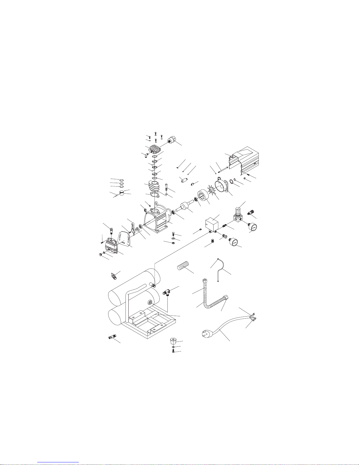
1
Model H3370 Pancake Air Compressor
15
15
16
17
22
23
19
21
26
25
24
68
69
2
3
4
7
7
11
18
14
9
31
30
20
27
5
6
8
6
10
28
67
78
37
34
12
13
38
29
33
32
30
60
48
36
35
39
61
73
44
45
79
46
42
43
41
40
57
58
59
56
55
53
52
62
49
50
47
54
51
52
75
74
30
70
32
71
32
72
76
63
77
65
66
64
Page 20

Model H3370/H3371Air Compressors
-18-
DESCRIPTION
REF
PART #
1 PB105M HEX BOLT M6-1 X 55
2 PLW03M LOCK WASHER 6MM
3 PH3370003 CYLINDER HEAD
4 PH3370004 90˚ ELBOW
3
⁄8 MPT X 3⁄4-16 UNF
5 PH3370005 GASKET
6 PH3370006 VALVE PLATE
7 PH3370007 VALVE BLADE
8 PH3370008 GASKET-VALVE SPACER
9 PH3370009 PISTON
10 PH3370010 GASKET-CYLINDER
11 PH3370011 CYLINDER
12 PSB31M CAP SCREW M8-1.25 X 25
13 PLW04M LOCK WASHER 8MM
14 PH3370014
GASKET-CYLINDER TO CRANKCASE
15 PH3370015 COMPRESSION RING
16 PH3370016 OIL RING
17 PH3370017 PISTON PIN 12 X 37.5MM
18 PR49M INT RETAINING RING 12MM
19 PH3370019 CONNECTING ROD
20 PH3370020 CRANK
21
PSB102M CAP SCREW M8-1.25 X 22LH
22 PH3370022 OIL BREATHER 16MM
23 PB91M HEX BOLT M6-1.0 X 18
24 PH3370024 OIL SIGHT GLASS G1⁄2
25 PH3370025 SEAL RING (M20 X 26 X3)
26 PH3370026 CRANKCASE COVER
27 PH3370027 GASKET
28 PH3370028 OIL SEAL 20 X 40 X 7
29 PH3370029 CRANKCASE
30 PN03M HEX NUT M8-1.25
31 PW01M FLAT WASHER 8MM
32 PW01M FLAT WASHER 8MM
33 PB20M HEX BOLT M8-1.25 X 35
34 PC120 CAPACITOR 120 MFD 250V
35 PW07M FLAT WASHER 3MM
36
PLW09M LOCK WASHER 3MM
37 PS12M PHLP HD SCR M3-.5 X 6
38 P6202 FRONT BEARING 6202
39 PH3370039 ROTATOR 67MM
40 P6202 REAR BEARING 6202
Model 3370
Page 21

Model H3370/H3371Air Compressors -19-
41 PH3370041 STATOR 115V/60HZ
42 PH3370042 FAN COVER
43 PH3370043 MOTOR FAN
44
PB106M
HEX BOLT M5-0.8 X 115
45 PLW01M LOCK WASHER 5MM
46 PH3370046 GASKET
47 PR02M EXT RETAINING RING 14MM
48 PH3370048 MOTOR COVER
49
PFB05 FLANGE BOLT M5-.8 X 15
50 PW03M FLAT WASHER 6MM
51 PH3370051 QUICK COUPLER
52 PH3370052 PRESSURE GAUGE
53 PH3370053 HEX BUSHING OD 1⁄4 X ID 1⁄8 MPT
54 PH3370054 REGULATOR
55 PH3370055 NIPPLE NPT 1⁄4 X 40
56 PH3370056 PRESSURE SWITCH-LF10
57 PH3370057 STEM ADAPTER 1⁄4 MPT
58 PH3370058 FLARE CONNECTOR 3⁄8 FPT
59 PH3370059 PLASTIC GASKET 6MM
60 PH3370060 SAFETY VALVE 1⁄4
NB 130 PSI
61 PH3370061 BUTTON
62 PH3370062 FLARE CONNECTOR 10MM
63 PH3370063 RELIEF COPPER PIPE 6 X 590
64 PH3370064 POWER CORD 14# X 2M
65 PH3370065 RING TERMINAL #10
66 PH3370066 FORK TERMINAL #10
67 PH3370067 GRIP COVER 25MM
68 PH3370068 CHECK VALVE
69 PH3370069 90˚ ELBOW
1
⁄8 MPT X 1⁄8 MPT
70 PH3370070 DRAIN VALVE 14MM
71 PH3370071 RUBBER FOOT
72 PB09M HEX BOLT M8-1.25 X 20
73 PH3370073 PLUG 1⁄4 MPT
74 PH3370074 TANK 4 GALLON PANCAKE
75 PH3370075 DISCHARGE PIPE (M12 X 360)
76 PH3370076 COOLER M12 X 380
77 PLN05 LOCK NUT 3/4-16
78 PH3370078 AIR INTAKE FILTER
79 PH3370079
THERMAL OVERLOAD PROTECTOR
DESCRIPTION
REF
PART #
Model 3370
Page 22
Model H3370/H3371Air Compressors-20-
1
Model H3371 Hot Dog Air Compressor
2
15
15
16
17
22
23
19
21
26
25
24
58
3
4
11
18
14
9
31
30
20
27
5
6
7
8
7
6
10
28
30
12
13
29
75
37
34
38
33
32
66
59
72
36
35
76
39
65
48
44
45
49
50
47
46
42
43
41
40
56
53
57
60
54
51
55
52
52
61
73
71
67
68
70
69
63
74
64
62
Page 23

Model H3370/H3371Air Compressors -21-
1 PB105M HEX BOLT M6-1 X 55
2 PLW03M LOCK WASHER 6MM
3 PH3370003 CYLINDER HEAD
4 PH3370004 90˚ ELBOW 3⁄8 MPT X 3⁄4-16 UNF
5 PH3370005 GASKET
6 PH3370006 VALVE PATCH
7 PH3370007 VALVE PLANK SPACER
8 PH3370008 GASKET
9 PH3370009 PISTON
10 PH3370010 GASKET-CYLINDER
11 PH3370011 CYLINDER
12 PSB31M CAP SCREW M8-1.25 X 25
13 PLW04M LOCK WASHER 8MM
14 PH3370014
GASKET-CYLINDER TO CRANKCASE
15 PH3370015 COMPRESSION RING
16 PH3370016 OIL RING
17 PH3370017 PISTON PIN 12 X 37.5MM
18 PR49M INT RETAINING RING 12MM
19 PH3370019 CONNECTING ROD
20 PH3370020 CRANK
21
PSB102M CAP SCREW M8-1.25 X 22LH
22 PH3370022 OIL BREATHER 16MM
23 PB91M HEX BOLT M6-1.0 X 18
24 PH3370024 OIL SIGHT GLASS G1⁄2
25 PH3370025 SEAL RING (M20 X 26 X 3)
26 PH3370026 CRANKCASE COVER
27 PH3370027 GASKET
28 PH3370028 OIL SEAL 20 X 40 X 7
29 PH3370029 CRANKCASE
30 PN03M HEX NUT M8-1.25
31 PW01M FLAT WASHER 8MM
32 PW01M FLAT WASHER 8MM
33 PB20M HEX BOLT M8-1.25 X 35
34 PC120 CAPACITOR 120 MFD 250V
35 PW07M FLAT WASHER 3MM
36
PLW09M LOCK WASHER 3MM
37 PS12M PHLP HD SCR M3-.5 X 6
38 P6202 FRONT BEARING 6202
39 PH3370039 ROTATOR 67MM
DESCRIPTION
REF
PART #
Model 3371
Page 24

Model H3370/H3371Air Compressors-22-
40 P6202 REAR BEARING 6202
41 PH3370041 STATOR 115V/ 60HZ
42 PH3370042 FAN COVER
43 PH3370043 MOTOR FAN
44 PB106M HEX BOLT M5-0.8 X 115
45 PLW01M LOCK WASHER 5MM
46 PH3370046 GASKET
47 PR02M EXT RETAINING RING 14MM
48 PH3370048 MOTOR COVER
49 PFB05 FlANGE BOLT M5-.8 X 15
50 PW03M FLAT WASHER 6MM
51 PH3370051 QUICK COUPLER
52 PH3370052 PRESSURE GAUGE
53 PH3370053 HEX BUSHING OD
1
⁄4
X ID
1
⁄8
MPT
54 PH3370054 REGULATOR
55 PH3370055 NIPPLE NPT
1
⁄4 X 40
56 PH3370056 PRESSURE SWITCH-LF10
57 PH3370057 STEM ADAPTER 1⁄4 MPT
58 PH3370060 SAFETY VALVE 1⁄4 NB 130 PSI
59 PH3370061 BUTTON
60 PH3370062 FLARE CONNECTOR ID 10MM
61 PH3370063 COPPER PIPE 6MM
62 PH3370064 POWER CORD 14# X 2M
63 PH3370065 RING TERMINAL #10
64 PH3370066 FORK TERMINAL #10
65 PH3371065 GRIP COVER 25MM
66 PH3371066 CHECK VALVE
67 PH3370070 DRAIN VALVE 14MM
68 PH3371068 CUSHION FOOT
69 PHTEK18 TAP SCREW #10 X
5
⁄8
70 PW04M FLAT WASHER 10MM
71 PH3371071 TANK TWO 2 GALLON HOT DOG
72 PH3370075 DISCHARGE PIPE (M12 X 360)
73 PH3370076 COOLER M12 X 380
74 PLN05 LOCK NUT 3/4-16
75 PH3370078 AIR INTAKE FILTER
76 PH3370079 THERMAL OVERLOAD PROTECTOR
DESCRIPTION
REF
PART #
Model 3371
Page 25

Model H3370/H3371Air Compressors -23-
NOTES
Page 26

Model H3370/H3371Air Compressors-24-
Grizzly Industrial, Inc. warrants every product it sells for a period of 1 year to the original
purchaser from the date of purchase. This warranty does not apply to defects due directly
or indirectly to misuse, abuse, negligence, accidents, repairs or alterations or lack of maintenance. This is Grizzly’s sole written warranty and any and all warranties that may be
implied by law, including any merchantability or fitness, for any particular purpose, are hereby limited to the duration of this written warranty. We do not warrant or represent that the
merchandise complies with the provisions of any law or acts unless the manufacturer so
warrants. In no event shall Grizzly’s liability under this warranty exceed the purchase price
paid for the product and any legal actions brought against Grizzly shall be tried in the State
of Washington, County of Whatcom.
We shall in no event be liable for death, injuries to persons or property or for incidental, contingent, special, or consequential damages arising from the use of our products.
To take advantage of this warranty, contact us by mail or phone and give us all the details.
We will then issue you a “Return Authorization Number,” which must be clearly posted on
the outside as well as the inside of the carton. We will not accept any item back without this
number. Proof of purchase must accompany the merchandise.
The manufacturers reserve the right to change specifications at any time because they constantly strive to achieve better quality equipment. We make every effort to ensure that our
products meet high quality and durability standards and we hope you never need to use this
warranty.
Please feel free to write or call us if you have any questions about the machine or the manual.
Grizzly Industrial, Inc.
1203 Lycoming Mall Circle
Muncy, PA 17756
Phone: (570) 546-9663
Fax: (800) 438-5901
E-Mail:
techsupport@grizzly.com
Web Site: http://www.grizzly.com
Thank you again for your business and continued support. We hope to serve you again
soon!
WARRANTY AND RETURNS
Page 27

Name__________________________________________________________
Street__________________________________________________________
City____________________State________Zip_________
Phone Number____________E-Mail___________________FAX____________
Model #_______________Serial#________________Order #______________
The following information is given on a voluntary basis. It will be used for marketing purposes to help
us develop better products and services. Of course, all information is strictly confidential.
WARRANTY CARD
9. How many of the machines checked above are
Grizzly? ____________
10. Which portable/hand held power tools do you own?
Check all that apply.
___Belt Sander ___Orbital Sander
___Biscuit Joiner ___Palm Sander
___Circular Saw ___Portable Planer
___Detail Sander ___Saber Saw
___Drill/Driver ___Reciprocating Saw
___Miter Saw ___Router
___Other_________________________________
11. What machines/supplies would you like Grizzly
Industrial to carry?
________________________________________
________________________________________
________________________________________
________________________________________
12. What new accessories would you like Grizzly
Industrial to carry?
________________________________________
________________________________________
________________________________________
________________________________________
13. What other companies do you purchase your tools
and supplies from?
_________________________________________
_________________________________________
_________________________________________
14. Do you think your purchase represents good value?
___Yes ___No
15. Would you recommend Grizzly to a friend?
___Yes ___No
16. Would you allow us to use your name as a reference for Grizzly customers in your area? Note: We
never use names more than three times.
___Yes ___No
17.Comments:________________________________
_________________________________________
_________________________________________
_________________________________________
1. How did you learn about us?
___Advertisement ___Friend
___Catalog ___Card Deck
___World Wide Web
___Other__________________________
2. What is your annual household income?
___$20,000-$29,999 ___$60,000-$69,999
___$30,000-$39,999 ___$70,000-$79,999
___$40,000-$49,999 ___$80,000-$89,999
___$50,000-$59,999 ___$90,000 +
3. What is your age group?
___20-29 ___50-59
___30-39 ___60-69
___40-49 ___70 +
4. How long have you been a woodworker?
___0 - 2 Years ___8 - 20 Years
___2 - 8 Years ___20+ Years
5. How would you rank your woodworking skills?
___Simple ___Advanced
___Intermediate ___Master Craftsman
6. What stationary woodworking tools do you own?
Check all that apply.
___Air Compressor ___Panel Saw
___Band Saw ___Planer
___Drill Press ___Power Feeder
___Drum Sander ___Radial Arm Saw
___Dust Collector ___Shaper
___Spindle Sander ___Jointer
___Table Saw ___Lathe
___Mortiser ___Wide Belt Sander
___Horiz.Boring Machine
___Vacuum Veneer Press
___Other______________________________
7. How many of your woodworking machines are
Grizzly? _____________
8. Which benchtop tools do you own? Check all
that apply.
___1"x42" Belt Sander ___6" - 8" Grinder
___5" - 8" Drill Press ___Mini Lathe
___8" Table Saw ___8" - 10" Bandsaw
___Scroll Saw ___Disc/Belt Sander
___Spindle/Belt Sander ___Mini Jointer
___10"-12"Thickness Planer
___Other______________________________
Page 28

FOLD ALONG DOTTED LINE
GRIZZLY INDUSTRIAL, INC.
P.O. BOX 2069
BELLINGHAM, WA 98227-2069
TAPE ALONG EDGES--PLEASE DO NOT NAIL
Name________________________________
Street________________________________
City______________State______Zip_______
Send a Grizzly Catalog to a friend:
Place
Stamp
Here
 Loading...