

Page 1

15" OPEN-END
WIDE-BELT SANDER
MODEL G9983
INSTRUCTION MANUAL
COPYRIGHT © OCTOBER, 2002 BY GRIZZLY INDUSTRIAL, INC.
WARNING: NO PORTION OF THIS MANUAL MAY BE REPRODUCED IN ANY SHAPE
OR FORM WITHOUT THE WRITTEN APPROVAL OF GRIZZLY INDUSTRIAL, INC.
PRINTED IN TAIWAN
Page 2

WARNING
Some dust created by power sanding, sawing, grinding, drilling, and other construction activities contains
chemicals known to the State of California to cause
cancer, birth defects or other reproductive harm.
Some examples of these chemicals are:
• Lead from lead-based paints.
• Crystalline silica from bricks, cement, and
other masonry products.
• Arsenic and chromium from chemically treated
lumber.
Your risk from these exposures varies, depending on
how often you do this type of work. To reduce your
exposure to these chemicals: work in a well ventilated
area, and work with approved safety equipment, such
as those dust masks that are specially designed to filter out microscopic particles.
Page 3

Table Of Contents
PAGE
1. SAFETY
SAFETY RULES FOR POWER TOOLS ..........................................................................................2-3
SAFETY RULES FOR THE WIDE BELT SANDER ............................................................................4
2. INTRODUCTION ........................................................................................................................................5
3. CIRCUIT REQUIREMENTS ......................................................................................................................6
220V SINGLE-PHASE..........................................................................................................................6
GROUNDING ......................................................................................................................................7
EXTENSION CORDS ..........................................................................................................................7
WIRING ................................................................................................................................................7
4. MACHINE FEATURES................................................................................................................................8
EXTERNAL FEATURES ......................................................................................................................8
CONTROL PANEL ..............................................................................................................................8
ACCESS DOORS ................................................................................................................................9
5. SET UP ......................................................................................................................................................10
UNPACKING ......................................................................................................................................10
PIECE INVENTORY ..........................................................................................................................10
HARDWARE RECOGNITION CHART ..............................................................................................11
CLEAN UP..........................................................................................................................................12
SITE CONSIDERATIONS ..................................................................................................................12
BEGINNING ASSEMBLY ..................................................................................................................13
HANDWHEEL HANDLE ....................................................................................................................13
PLATEN..............................................................................................................................................14
AIR HOSE ..........................................................................................................................................15
SANDING BELT ................................................................................................................................15
SANDING BELT TENSION ................................................................................................................16
PRESSURE ROLLERS ......................................................................................................................16
DUST COLLECTION..........................................................................................................................17
TEST RUN ....................................................................................................................................17-18
RECOMMENDED ADJUSTMENTS ..................................................................................................18
6. OPERATIONS ..........................................................................................................................................19
BEFORE STARTING..........................................................................................................................19
CHOOSING SANDPAPER ................................................................................................................19
CONVEYOR HEIGHT ........................................................................................................................20
FEED BELT SPEED ..........................................................................................................................20
LOAD METER ....................................................................................................................................21
OPERATION ......................................................................................................................................21
PLATEN DEPTH ................................................................................................................................22
CLEANING PADS ..............................................................................................................................22
7. MAINTENANCE ........................................................................................................................................23
GENERAL ..........................................................................................................................................23
LUBRICATION ..................................................................................................................................23
CLEANING SANDING BELTS ..........................................................................................................23
EMPTYING FILTERS ........................................................................................................................23
MAINTENANCE LOG ........................................................................................................................24
8. SERVICE ADJUSTMENTS ......................................................................................................................25
OSCILLATION TIMING ................................................................................................................25-26
OSCILLATION SPEED ......................................................................................................................26
OSCILLATION RETURN....................................................................................................................27
LIMIT SWITCHES ..............................................................................................................................27
PRESSURE ROLLER DEPTH ..........................................................................................................28
PRESSURE ROLLER TENSION ......................................................................................................29
FEED BELT TENSION ......................................................................................................................30
FEED BELT TRACKING ....................................................................................................................30
V-BELT TENSION ..............................................................................................................................31
REPLACING V-BELTS..................................................................................................................31-32
PLATEN GRAPHITE ..........................................................................................................................33
AIR SYSTEM......................................................................................................................................33
REPLACING BRAKES ......................................................................................................................34
SERVICE LOG ..................................................................................................................................35
9. CLOSURE ................................................................................................................................................36
DATA SHEET ........................................................................................................................................................37
AIR SYSTEM..........................................................................................................................................................38
WIRING DIAGRAM ..........................................................................................................................................39-41
PARTS BREAKDOWN ....................................................................................................................................42-51
TROUBLESHOOTING......................................................................................................................................52-53
WARRANTY AND RETURNS................................................................................................................................54
Page 4

5. KEEP CHILDREN AND VISITORS
AWAY. All children and visitors should be
kept at a safe distance from work area.
6. MAKE WORKSHOP CHILD PROOF with
padlocks, master switches, or by removing
starter keys.
7. NEVER FORCE TOOL. It will do the job
better and safer at the rate for which it was
designed.
8. USE RIGHT TOOL. Do not force tool or
attachment to do a job for which it was not
designed.
1. KEEP GUARDS IN PLACE and in working
order.
2. REMOVE ADJUSTING KEYS AND
WRENCHES. Form habit of checking to
see that keys and adjusting wrenches are
removed from tool before turning on.
3. KEEP WORK AREA CLEAN. Cluttered
areas and benches invite accidents.
4. NEVER USE IN DANGEROUS ENVIRONMENT. Do not use power tools in
damp or wet locations, or where any flammable or noxious fumes may exist. Keep
work area well lighted.
-2- G9983 15" Open-End Wide-Belt Sander
Safety Instructions For Power Tools
SECTION 1: SAFETY
For Your Own Safety Read Instruction
Manual Before Operating This Equipment
Indicates an imminently hazardous situation which, if not avoided,
WILL result in death or serious injury.
Indicates a potentially hazardous situation which, if not avoided,
COULD
result in death or serious injury.
Indicates a potentially hazardous situation which, if not avoided,
MAY
result in minor or moderate injury. It may also be used to alert
against unsafe practices.
This symbol is used to alert the user to useful information about
proper operation of the equipment.
The purpose of safety symbols is to attract your attention to possible hazardous conditions.
This manual uses a series of symbols and signal words which are intended to convey the level
of importance of the safety messages. The progression of symbols is described below.
Remember that safety messages by themselves do not eliminate danger and are not a substitute for proper accident prevention measures.
NOTICE
Page 5

G9983 15" Open-End Wide-Belt Sander -3-
9. USE PROPER EXTENSION CORD. Make
sure your extension cord is in good condition. Conductor size should be in accordance with the chart below. The amperage
rating should be listed on the motor or tool
nameplate. An undersized cord will cause
a drop in line voltage resulting in loss of
power and overheating. Your extension
cord must also contain a ground wire and
plug pin. Always repair or replace extension cords if they become damaged.
Minimum Gauge for Extension Cords
10. WEAR PROPER APPAREL. Do not wear
loose clothing, gloves, neckties, rings,
bracelets, or other jewelry which may get
caught in moving parts. Non-slip footwear
is recommended. Wear protective hair covering to contain long hair.
11. ALWAYS USE SAFETY GLASSES. Also
use face or dust mask if cutting operation
is dusty. Everyday eyeglasses only have
impact resistant lenses, they are NOT
safety glasses.
12. SECURE WORK. Use clamps or a vise to
hold work when practical. It’s safer than
using your hand and frees both hands to
operate tool.
13. NEVER OVERREACH. Keep proper foot-
ing and balance at all times.
LENGTH
AMP RATING 25ft 50ft 100ft
0-6 18 16 16
7-10 18 16 14
11-12 16 16 14
13-16 14 12 12
17-20 12 12 10
21-30 10 10 No
Safety Instructions For Power Tools
14. MAINTAIN TOOLS WITH CARE. Keep
tools sharp and clean for best and safest
performance. Follow instructions for lubricating and changing accessories.
15. DISCONNECT TOOLS before servicing
and changing accessories, such as blades,
bits, cutters, and the like.
16. REDUCE THE RISK OF UNINTENTIONAL STARTING. Make sure switch is in off
position before plugging in. Also, the magnetic switch on this machine may start if the
switch gets bumped hard enough.
17. USE RECOMMENDED ACCESSORIES.
Consult the owner’s manual for recommended accessories. The use of improper
accessories may cause risk of injury.
18. CHECK DAMAGED PARTS. Before fur-
ther use of the tool, a guard or other part
that is damaged should be carefully
checked to determine that it will operate
properly and perform its intended function.
Check for alignment of moving parts, binding of moving parts, breakage of parts,
mounting, and any other conditions that
may affect its operation. A guard or other
part that is damaged should be properly
repaired or replaced.
19. NEVER LEAVE TOOL RUNNING UNATTENDED. TURN POWER OFF. Do not
leave tool until it comes to a complete stop.
20. NEVER USE UNDER THE INFLUENCE of
alcohol or drugs, or when tired.
21. NEVER ALLOW UNSUPERVISED OR
UNTRAINED PERSONNEL TO OPERATE THE MACHINE. Make sure any
instructions you give in regards to the operation of the machine are approved, correct,
safe, and clearly understood.
Page 6

-4- G9983 15" Open-End Wide-Belt Sander
Additional Safety Instructions
For The Wide-Belt Sander
• DO NOT allow anyone to stand at the out-
feed end when feeding your stock.
• DO NOT jam workpiece into the machine
during operation. Firmly grasp the workpiece in both hands and ease it into the
machine using light pressure.
• DO NOT wear loose clothing while operat-
ing this machine. Roll up or button sleeves
at the cuff.
• DO NOT sand any stock thinner than
1
⁄8''.
DO NOT sand stock shorter than 9''
• DO NOT attempt to sand thin stock by
using a “dummy” board under your workpiece.
• DO NOT place hands near, or in contact
with, sanding belts during operation.
• DO NOT allow fingers to get pinched
between board and conveyor belt during
operation. This may pull the operator’s
hand into the machine and cause serious
injury or death!
• ALWAYS WEAR A DUST MASK in addi-
tion to using a dust collector. This machine
produces wood dust that may cause allergic reactions or respiratory problems.
• NEVER leave the machine running unat-
tended.
• NEVER operate the sander without an
adequate dust collection system in place
and operating correctly.
• NEVER operate sander with the access
doors open.
• ANY PROBLEM, with the exception of
conveyor belt tracking, that is concerned
at all with any moving parts or accessories
must be investigated and corrected with
the power disconnected and after all moving parts have come to a complete stop.
Never attempt to adjust conveyor belt
tracking when the sanding belts are
engaged.
• REPLACE sanding belt when it becomes
worn.
• ALWAYS inspect board stock for nails,
staples, knots, and other imperfections
that could be dislodged and thrown from
the machine during sanding operations.
• MAKE SURE all operators have read and
understand this manual before allowing
them to use the sander. This includes
employees, students and family!
Operating this equipment has the potential
for creating flying debris which can cause
eye injury. Always wear safety glasses or
goggles when operating equipment.
Everyday glasses or reading glasses only
have impact resistant lenses, they are not
safety glasses. Be certain the safety glasses you wear meet the appropriate standards
of the American National Standards
Institute (ANSI).
As with all power tools, there is danger
associated with Wide-Belt Sanders.
Accidents are frequently caused by lack of
familiarity or failure to pay attention. Use
this tool with respect and caution to lessen
the possibility of operator injury. If normal
safety precautions are overlooked or
ignored, serious personal injury may occur.
Page 7

G9983 15" Open-End Wide-Belt Sander -5-
SECTION 2: INTRODUCTION
We are also pleased to provide this manual with
the Model G9983. It was written to guide you
through assembly, review safety considerations,
and cover general operating procedures. It represents our effort to produce the best documentation possible. If you have any comments regarding this manual, please write to us at the address
below:
Grizzly Industrial, Inc.
C
/O Technical Documentation
P.O. Box 2069
Bellingham, WA 98227-2069
Most important, we stand behind our machines. If
you have any service questions or parts requests,
please call or write us at the location listed below.
Grizzly Industrial, Inc.
1203 Lycoming Mall Circle
Muncy, PA 17756
Phone: (570) 546-9663
Fax: (800) 438-5901
E-Mail: techsupport@grizzly.com
Web Site: http://www.grizzly.com
The specifications, drawings, and photographs
illustrated in this manual represent the Model
G9983 as supplied when the manual was prepared. However, owing to Grizzly’s policy of continuous improvement, changes may be made at
any time with no obligation on the part of Grizzly.
For your convenience, we always keep current
Grizzly manuals available on our website at
www.grizzly.com
. Any updates to your machine
will be reflected in these manuals as soon as they
are complete.
We are proud to offer the Grizzly Model G9983
Wide-belt Sander. Your machine is part of a
growing Grizzly family of fine woodworking
machinery. When used according to the guidelines set forth in this manual, you can expect
years of trouble-free, enjoyable operation and
proof of Grizzly’s commitment to customer satisfaction.
With its 15" open end, the Model G9983 has the
capability to sand a 30" wide workpiece in two
passes. This machine also features a 5 HP sanding belt motor and a
1
⁄4 HP feed motor, independent conveyor and sanding belt motor control,
pneumatic belt tensioning and tracking, two rubber
rollers, a load meter, a safety shut-off bar, and a 5"
dust port.
Read the manual before
assembly and operation.
Become familiar with
the machine and its
operation before beginning any work. Serious
personal injury may
result if safety or operational information is not
understood or followed.
Page 8

-6- G9983 15" Open-End Wide-Belt Sander
SECTION 3: CIRCUIT REQUIREMENTS
220V Single-Phase
The Model G9983 features a 5 HP, 220V singlephase motor. This motor will safely draw about 30
amps under load. The Model G9983 also features
a
1
⁄4 HP feed motor that draws approximately 1.8
amps under load. Total amperage draw for this
machine is approximately 32 amps under load.
Use a 35 amp circuit breaker for the Model
G9983. Make sure the wiring in your circuit is
rated to handle the amperage draw from your
machine. If frequent circuit failure occurs when
using the sander, contact our Service
Department. The sander must be connected to its
own dedicated circuit and should not share a circuit with any other machine. A standard 2-pole
breaker is necessary for use with the sander.
We recommend using a NEMA-style 6-50 plug
and outlet (similar to the one shown in Figure 1)
for the Model G9983. You may also “hard-wire”
the sander directly to your panel, provided you
place a disconnect near the machine. Check the
electrical codes in your area for specifics on
wiring requirements.
Figure 1. Plug configuration for 220V, single-
phase 6-50 plug and outlet.
Page 9

G9983 15" Open-End Wide-Belt Sander -7-
The Model G9983 comes prewired for 220 volt
operation. Wiring diagrams are provided at the
back of this manual should it be necessary to
repair or revise the wiring. Always consult a qualified electrician when doing any electrical work on
this equipment.
Wiring
We have covered some basic electrical
requirements for the safe operation of your
Sander. These requirements are not necessarily comprehensive. You must be sure
that your particular electrical configuration
complies with local and state codes.
Ensure compliance by checking with your
local municipality or a licensed electrician.
Extension Cords
We do not recommend the use of extension
cords on 220V equipment. It is much better to
arrange the placement of your equipment and the
installed wiring to eliminate the need for extension cords.
Grounding
In the event of an electrical short, grounding
reduces the risk of electric shock by providing a
path of least resistance to disperse electric current. This tool is equipped with an electric cord
that has an equipment-grounding conductor
which must be properly connected to a grounding
plug. The plug must be plugged into a matching
outlet that is properly installed and grounded in
accordance with all local codes and ordinances.
Improper connections of the electrical-grounding
conductor can result in the risk of electric shock.
The conductor with green or green and yellow
striped insulation is the electrical-grounding conductor. If repair or replacement of the electric
cord or plug is necessary, do not connect the
equipment grounding conductor to a live terminal.
This equipment must be
grounded. Verify that any
existing electrical outlet
and circuit you intend to
plug into is actually
grounded. Under no circumstances should the
grounding pin from any
three-pronged plug be
removed. Serious injury
may occur.
Page 10
-8- G9983 15" Open-End Wide-Belt Sander
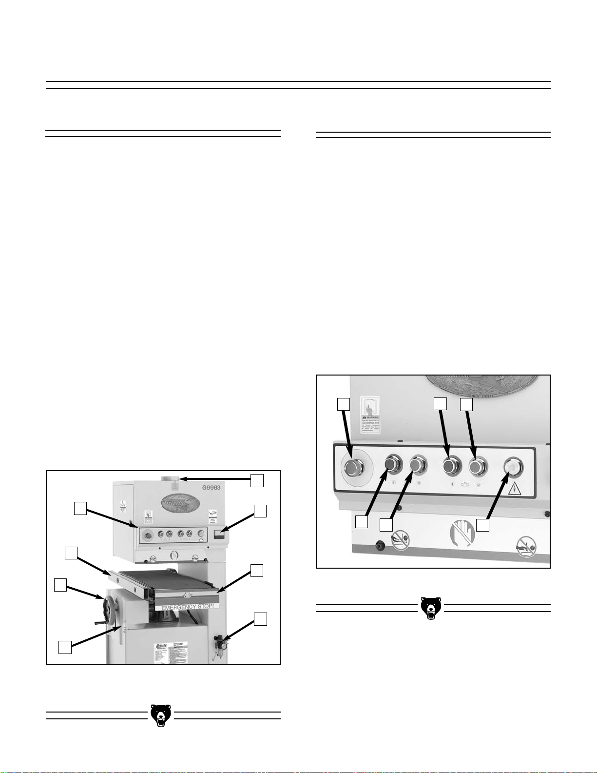
SECTION 4: MACHINE FEATURES
External Features
To help you understand the set up and operation
instructions, we recommend that you become
familiar with the basic features of your new
sander.
Please match up the list below with the letters in
Figure 2 to identify the external sander compo-
nents.
A. Control Panel
B. Table Extension
C. Conveyor Height Handwheel
D. Conveyor Height Gauge
E. Dust Port
F. Load Meter
G. Emergency Stop Bar
H. Pressure Regulator
B
A
C
D
F
G
H
E
Figure 2. These are the basic external
components of the sander.
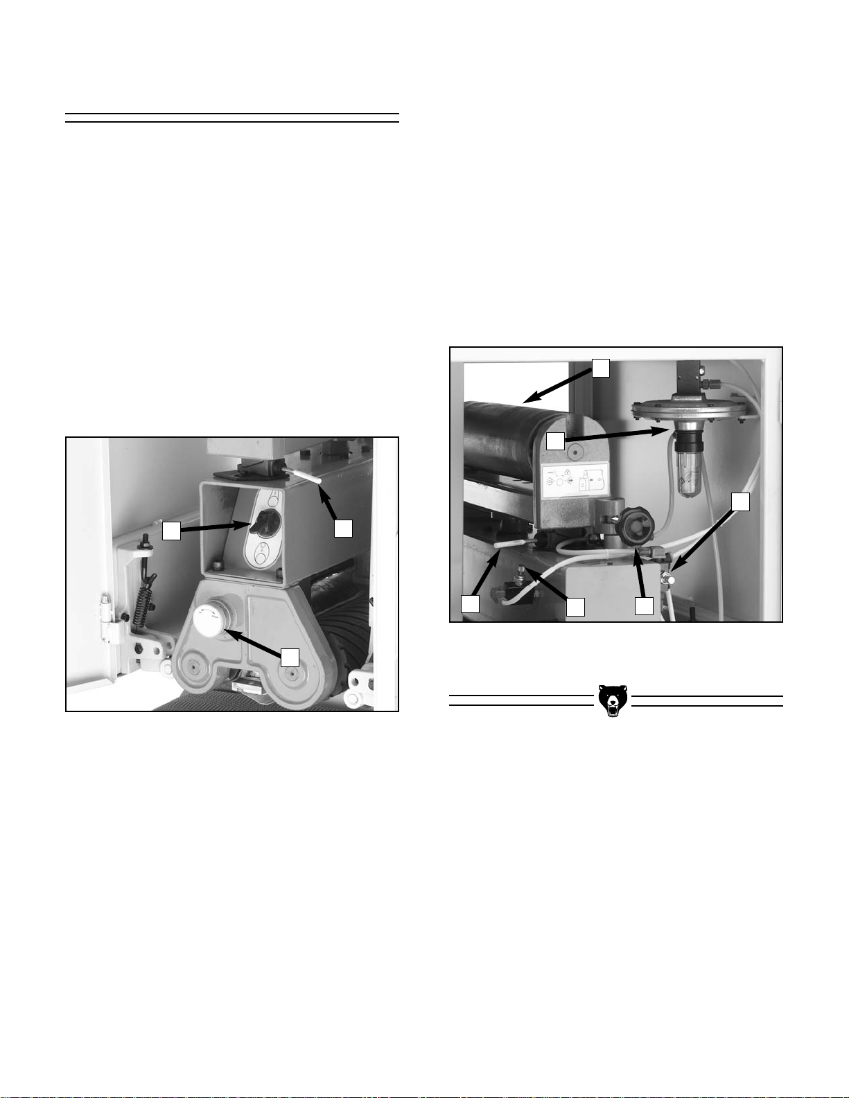
Control Panel
The control panel houses the main power switch,
the feed belt ON/OFF buttons and the sanding
belt ON/OFF buttons. Please refer to Figure 3 to
identify these controls.
A. Main Power ON / Emergency STOP switch.
B. Sanding Belt OFF button.
C. Sanding Belt ON button.
D. Feed Belt OFF button.
E. Feed Belt ON button.
F. Power Indicator Light
Figure 3. These are the main power controls.
A
D
E
B
C
F
Page 11
G9983 15" Open-End Wide-Belt Sander -9-
Access Doors
There are access doors located on each side of
the sander. Throughout the manual, we refer to
these doors as the “left-hand access door” and
the “right-hand access door.” These terms are
referenced as if you are facing the front of the
machine.
Figure 4 shows the layout behind the left-hand
access door.
A. Limit Switch
B. Sanding Belt Tension Switch
C. Platen Adjustment Knob
Figure 4. These items are behind the
left-hand access door.
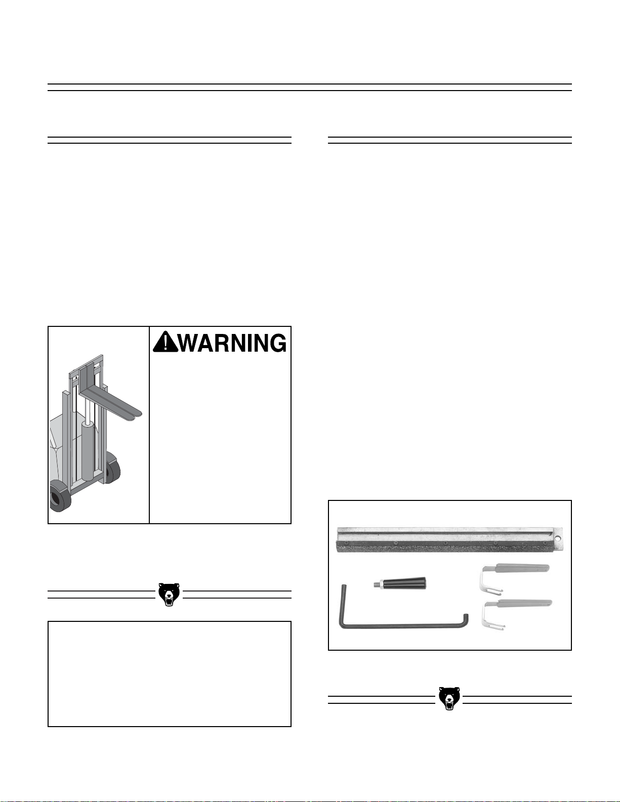
Figure 5 shows the layout behind the right-hand
access door.
A. Oscillating Roller
B. Oscillation Air Filter
C. Limit Switch
D. Oscillation Return Valve
E. Oscillation Speed Valve
F. Oscillation Timing Knob
A
B
C
Figure 5. These items are behind the
right-hand access door.
A
B
C
D
E
F
Page 12
Unpacking
The Model G9983 Wide-belt Sander is shipped
from the manufacturer in a carefully packed carton. If you discover your machine is damaged
after you have signed for delivery, and the truck
and driver are gone, you will need to file a freight
claim with the carrier. Save the containers and all
packing materials for possible inspection by the
carrier or its agent. Without the packing materials,
filing a freight claim can be difficult. If you need
assistance determining whether you need to file a
freight claim, or with the procedure to file one,
please contact our Customer Service.
Piece Inventory
After all the parts have been removed from the
carton, you should have:
• Sanding Unit
• Tool Box
• Combo Wrench 8/10MM
• Combo Wrench 11/13MM
• Combo Wrench 12/14MM
• Combo Wrench 17/19MM
• Combo Box-Wrench 30/37MM
• Phillips Screwdriver
• Hex Wrench Set
• Platen Puller
• Platen
•Door Handle (2)
• Handwheel Handle
• Sanding Belt #180
• Sanding Belt #240
In the event that any non-proprietary parts are
missing (e.g. a nut or a washer), we would be
glad to replace them, or for the sake of expediency, replacements can be obtained at your local
hardware store. Loose parts in the sander crate
(not including hardware) are shown in Figure 6.
When you are completely satisfied with the condition of your shipment, you should inventory its
parts.
NOTICE
A full parts list and breakdown can be found
toward the end of this manual. For easier
assembly, or to identify missing parts,
please refer to the detailed illustrations at
the end of the manual.
The Model G9983 is a
heavy machine—
approx. 1000 lb. DO
NOT over-exert yourself
while unpacking or
moving your machine.
You will need assistance and power equipment. Serious personal
injury may occur if safe
moving methods are not
followed.
Figure 6. Loose parts (not including hardware)
for the Model G9983.
-10- G9983 15" Open-End Wide-Belt Sander
SECTION 5: SET UP
Page 13
G9983 15" Open-End Wide-Belt Sander -11-
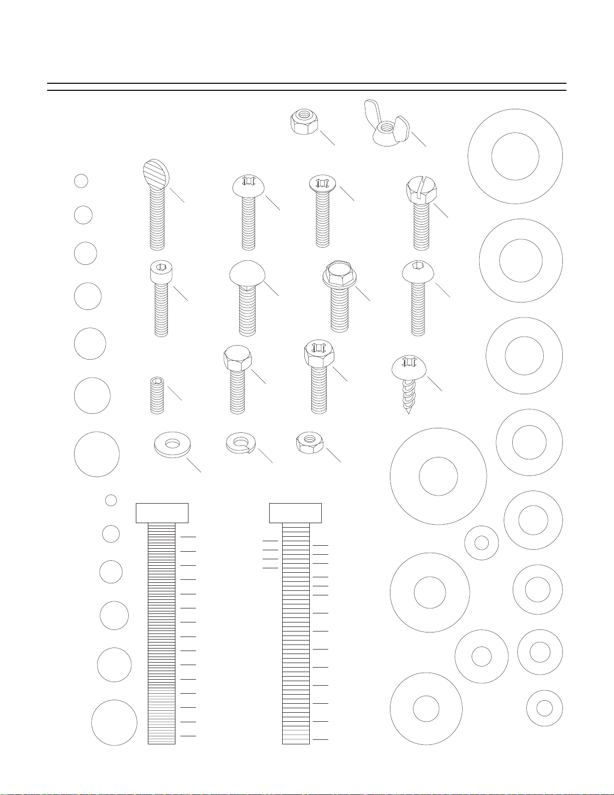
Hardware Recognition Chart
Use this chart to match up hardware
pieces during the assembly process!
#
10
Lock
Nut
Wing
Nut
S
A
W
D
I
A
R
E
H
M
E
T
⁄8''
E
R
5
1
⁄4''
Thumb
Screw
Phillips
Head
5
⁄16''
3
⁄8''
7
Cap
Screw
⁄16''
Screw
Carriage
Bolt
Hex
1
⁄2''
Setscrew
5
⁄8''
Head
Bolt
Lock
Washer
MEASURE BOLT DIAMETER BY PLACING INSIDE CIRCLE
4mm
6mm
5mm
10mm
8mm
15mm
20mm
Washer
1
⁄4''
3
⁄8''
1
⁄2''
5
⁄8''
25mm
10mm
30mm
35mm
40mm
45mm
12mm
LINES ARE 1MM APART
50mm
55mm
60mm
⁄16'' INCH APART
1
65mm
16mm
70mm
75mm
LINES ARE
Countersunk
Phillips
Head
Screw
Flange
Bolt
Phillips
Head
Hex
Bolt
Hex
Nut
5
⁄16''
7
⁄16''
9
⁄16''
3
⁄4''
7
⁄8''
1''
11⁄4''
1
⁄2''
1
3
⁄4''
1
2
1
⁄4''
2
1
⁄2''
2
3
⁄4''
2
3
Slotted
Screw
A
S
H
W
D
I
A
R
9
⁄16''
M
E
T
E
R
E
Button
Head
D
I
A
A
H
S
W
R
E
M
E
T
⁄2''
E
R
1
Screw
Phillips
Head
Sheet
Metal
Screw
D
I
A
R
12mm
D
I
A
D
I
A
M
M
E
T
E
R
D
I
A
R
M
E
H
E
S
T
E
A
R
W
M
4mm
E
T
E
R
D
I
A
R
M
E
E
H
T
S
E
A
R
W
6mm
E
T
E
R
A
S
S
W
H
A
S
A
E
H
E
W
E
H
W
R
10mm
R
8mm
WASHERS ARE MEASURED BY THE INSIDE DIAMETER
D
I
A
R
W
H
S
A
M
E
T
7
⁄16''
E
R
D
I
R
A
M
E
W
H
S
E
3
T
⁄8''
E
R
D
I
A
R
M
E
E
5
T
⁄16''
E
A
R
W
D
I
A
R
M
E
H
E
1
S
⁄4''
T
A
E
R
W
D
I
R
A
E
M
H
E
S
T
A
E
R
W
#
10
E
H
S
A
Page 14

-12- G9983 15" Open-End Wide-Belt Sander
Site Considerations
FLOOR LOAD
Your new wide-belt sander represents a large
weight load in a moderate sized footprint. Most
shop floors will be adequate for the weight of the
wide-belt sander; however, some floors may
require additional support. Contact an architect or
structural engineer if you have any question
about the ability of your floor to handle the weight.
WORKING CLEARANCES
Working clearances can be thought of as the distances between machines and obstacles that
allow safe operation of every machine without
limitation. Consider existing and anticipated
machine needs, size of material to be processed
through each machine, and space for auxiliary
stands and/or work tables. Also consider the relative position of each machine to one another for
efficient material handling. Be sure to allow yourself sufficient room to safely run your machines in
any foreseeable operation.
LIGHTING AND OUTLETS
Lighting should be bright enough to eliminate
shadow and prevent eye strain. Electrical circuits
should be dedicated or large enough to handle
combined motor amp loads. Outlets should be
located near each machine so power or extension cords are not obstructing high-traffic areas.
Be sure to observe local electrical codes for proper installation of new lighting, outlets or circuits.
Make your shop “child
safe.” Ensure that your
workplace is inaccessible to
children by closing and
locking all entrances when
you are away. Never allow
visitors in your shop when
assembling, adjusting or
operating equipment.
Clean Up
The unpainted surfaces are coated with a waxy
oil to protect them from corrosion during shipment. Remove this protective coating with a solvent cleaner or citrus-based degreaser such as
Grizzly’s G7895 Degreaser. To clean thoroughly,
some parts may need to be removed. For opti-
mum performance from your machine, make
sure you clean all moving parts or sliding
contact surfaces that are coated. Avoid chlo-
rine-based solvents as they may damage painted
surfaces should they come in contact. Always follow the manufacturer’s instructions when using
any type of cleaning product.
Do not use gasoline or
other petroleum-based
solvents to clean with.
They have low flash
points which make them
extremely flammable. A
risk of explosion and
burning exists if these
products are used.
Do not smoke while using
solvents. A risk of explosion or fire exists and may
result in serious personal
injury.
Many of the solvents
commonly used to clean
machinery can be toxic
when inhaled or ingested. Always work in wellventilated areas far from
potential ignition sources
when dealing with solvents. Use care when disposing of waste rags and
towels to be sure they do
not create fire or environmental hazards.
Page 15

G9983 15" Open-End Wide-Belt Sander -13-
Beginning Assembly
Most of your new wide-belt sander has been
assembled at the factory, but some setup is
required after delivery. We have organized the
setup process into steps. Please make sure the
sander is placed in its final position in your shop
and follow along in the order presented in this
section.
Keep loose clothing out
of the way of machinery
and keep hair pulled
back.
Wear safety glasses during the entire setup
process. Failure to comply may result in serious
personal injury.
Disconnect power to the
machine when performing any setup or assembly. Failure to do this
may result in serious
personal injury.
Some metal parts may
have sharp edges on
them after they are
formed. Please examine
the edges of all metal
parts before handling
them. Failure to do so
could result in injury.
NOTICE
The waxy grease must be completely
cleaned from the table column for smooth
table height adjustments.
Handwheel Handle
To install the handwheel handle:
1. Thread the handle into the handwheel as
shown in Figure 7.
2. After handle is completely threaded down,
tighten the jamnut so the handle will not
come loose. Make sure to leave the plastic
sleeve loose enough to rotate when you
crank the handwheel.
Figure 7. Install handle onto handwheel.
Page 16
-14- G9983 15" Open-End Wide-Belt Sander
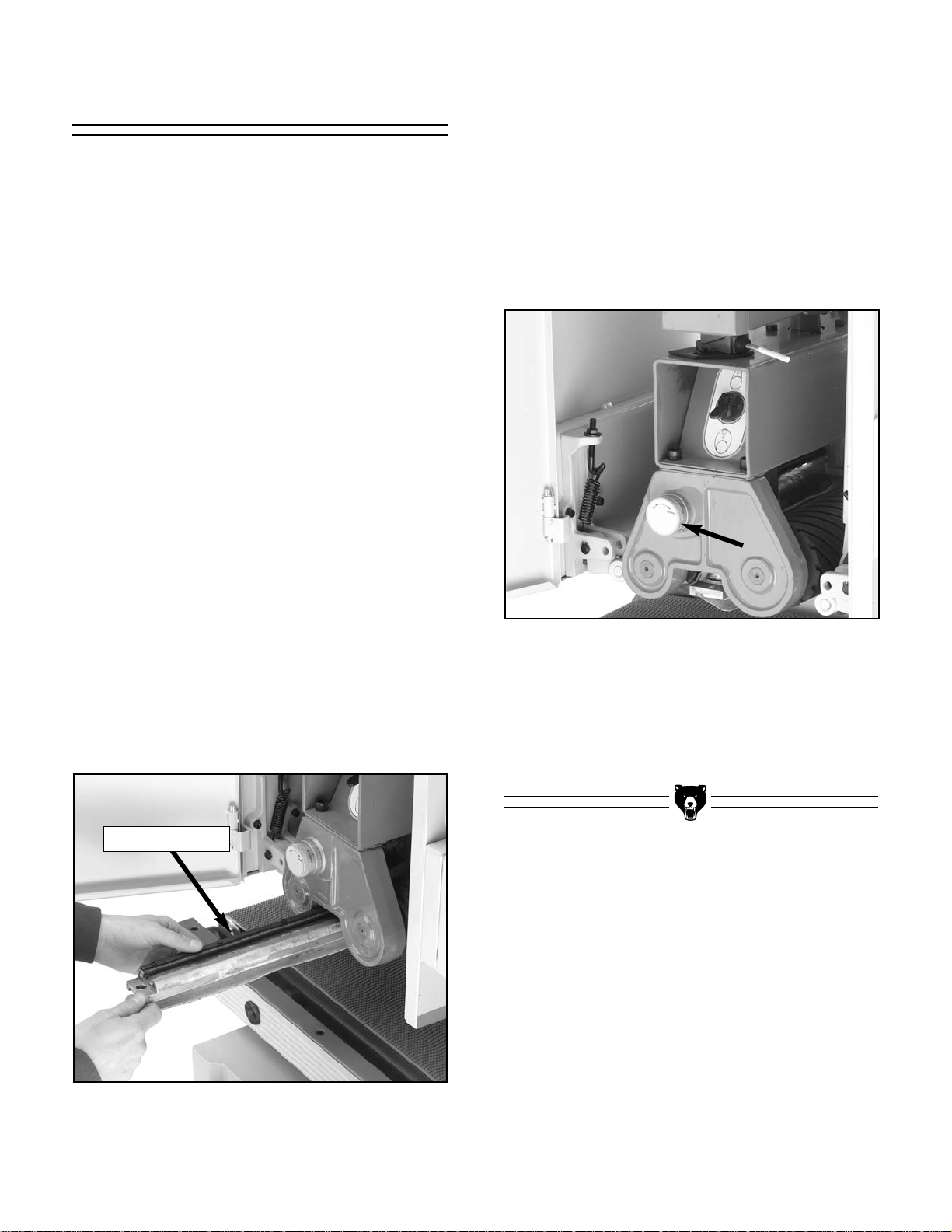
Platen
The housing for the platen can be accessed by
opening the door on the left-hand side of the
machine.
A graphite sheet is mounted on the platen. Before
installing, make sure that the graphite sheet is
mounted on the left-hand side of the platen, as it
will be inserted. Figure 8 shows the platen being
installed correctly.
The direction of the graphite sheet is important
because it must wrap around the platen in the
same direction as the sanding belt rotates. If not,
the sanding belt will unwrap the graphite sheet,
exposing the sanding belt to the metal body of the
platen. Note: the graphite sheet on the platen is
considered a “consumable” item, similar to the
sanding belts, and normal wear and tear from
machine operation is not covered under warranty. For additional information on the platen, turn to
page 33.
To insert the platen:
1. Line up the platen dovetail with the housing
so it is positioned as described above.
2. Slide the platen into the housing as far as it
can go.
Figure 8. Install the platen with the graphite
sheet on the left-hand side.
Figure 9. Use this knob to raise/lower the platen.
3. Place a straightedge across both lower belt
rollers and rotate the adjustment knob until
the platen barely touches the straightedge.
The platen should now be set even with the
belt rollers.
The platen must now be set even with the sanding rollers.
To set the platen even with the belt rollers:
1. Lower the conveyor table as far as it will go.
2. Open the access door on the left-hand side
and locate the platen adjustment knob
shown in Figure 9.
Graphite Sheet
Page 17
G9983 15" Open-End Wide-Belt Sander -15-
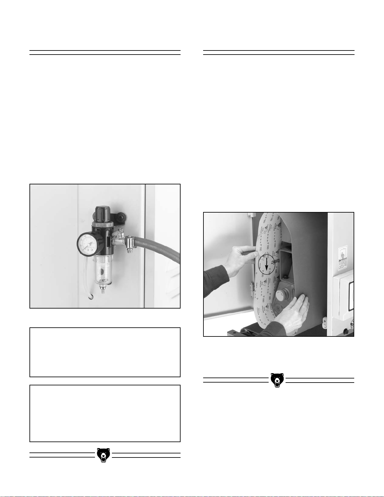
Air Hose
Figure 10. Secure air hose with a hose clamp.
The air hose connection is located at the regulator on the front of the machine.
To connect the air hose:
1. Fit the hose over the regulator nozzle.
2. Secure the hose with a hose clamp as shown
in Figure 10 and turn on your air compres-
sor.
3. Regulate the air pressure to 75 PSI. This
is the normal operating pressure for the
Model G9983.
NOTICE
DO NOT exceed 75 lb. of air pressure.
Damage to the machine components may
result.
NOTICE
The main shut off valve should remain
closed until air pressure is needed. This will
reduce wear and tear on the air system components.
Figure 11. Place belt over the three belt rollers
to install. Make sure arrows on inside of belt
point in the direction of rotation.
Sanding Belt
The Model G9983 is designed for 16" x 48" sanding belts.
To install a sanding belt:
1. Open the left-hand side door for access.
2. Make sure the greasy protective coating has
been cleaned from the metal belt roller
before installing sanding belt.
3. Fit the sanding belt completely over the three
sanding rollers as shown in Figure 11. The
belt will move counter-clockwise during rotation—make sure that the arrows on the
inside of the belt point in the direction of rotation.
Page 18
-16- G9983 15" Open-End Wide-Belt Sander
Pressure Rollers
Always keep the pressure rollers set below
the level of the sanding roller. If the pressure rollers are even, or higher than the
sanding roller, the wood WILL be propelled
from the sander at a high rate of speed.
This situation could cause serious personal injury.
The pressure rollers have been set at the factory,
but for increased personal safety, you should verify that they are below the sanding belt.
To check the feed pressure:
1. Disconnect the sander from the power
source!
2. Place a piece of scrap wood of uniform thick-
ness across the conveyor so it spans both
front and rear pressure rollers at the same
time.
3. Make sure the platen is even with the sand-
ing belt rollers.
4. With the air pressure connected, the sanding
belt installed, and the belt tension switch ON,
slowly raise the conveyor and verify that the
board touches both pressure rollers before it
touches the sanding belt.
If the board does not touch both pressure
rollers before it touches the sanding belt,
then the pressure rollers must be adjusted before operation. See Section 8:
Service Adjustments for step-by-step
instructions on how to do this.
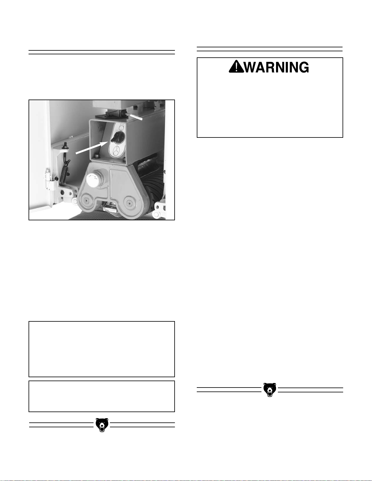
Sanding Belt Tension
Figure 12. This is the belt tension switch.
The sanding belt tension is controlled by a switch
located inside the upper portion of the machine
(see Figure 12). To locate it, open the access
door on the left-hand side of the sander.
To Tighten Belt Tension:
Flip the switch up. The vertical cylinder will automatically tighten the top roller to the correct tension.
To Loosen Belt Tension:
Flip the switch down. The vertical cylinder will
automatically loosen the belt tension for belt
removal.
NOTICE
The belt tension switch is part of the air
control system. This means the machine
must have air pressure for the switch to
work correctly.
NOTICE
Always tighten belt before starting sander!
Page 19

G9983 15" Open-End Wide-Belt Sander -17-
Dust Collection
The dust collection port is located on top of the
sander and measures 5" in diameter. It will be
necessary to attach a 5" dust collection pipe over
this port before operation. If you have rigid ducts
in your dust collection system, we recommend
that you connect the ducts to your sander with
flexible hose. The flex-hose easily attaches with a
5" hose clamp and it absorbs any movement that
may occur during operation. Please refer to the
Grizzly catalog for current price and ordering
information.
Your dust collector must be able to move 8001200 CFM at the Wide-belt Sander. If you have
a remotely located dust collector, or if you are
operating more than one machine at a time,
ensure that your dust collector has the capacity
and power to meet this requirement. A fine layer
of dust may be present on your stock as it comes
out of the sander. This is normal.
Always wear a dust mask
in addition to using a
dust collector. Dust
masks filter out the
smaller particles of dust
that dust collectors cannot trap.
DO NOT operate the Model G9983 without an
adequate dust collection system. This
machine creates substantial amounts of
wood dust while in operation. Failure to use
a dust collection system may result in short
and long-term respiratory illness.
Test Run
Once the assembly is complete and the adjustments are done to your satisfaction, you are
ready to test run the sander.
Before you test run your machine:
1. Read back through Section 1: Safety
Instructions, Section 4: Assembly, and the
previous instructions in this section to make
sure that all precautions have been taken for
safe operation.
2. Make sure the machine is connected to an
air compressor and the pressure gauge on
the sander reads 75 PSI.
3. Make sure that any tools or foreign objects
have been removed from the machine.
4. Last but not least, make sure the wiring is
correct. Did you follow the instructions from
Section 2: Circuit Requirements? If you are
not confident with the wiring, go back and
double check that all precautions have been
taken to ensure safety to the operator and
the circuit. When you are confident, connect
the machine to the power source. The power
indication light on the control panel should
light up.
To test run the sander:
1. Turn on the power supply at the main panel.
DO NOT attempt to investigate or adjust any
features of the machine while it is running.
Wait until the machine is turned off,
unplugged and all working parts have come
to a rest before you do anything! Failure to
do so could result in severe personal injury.
Page 20

-18- G9983 15" Open-End Wide-Belt Sander
Long term exposure to
this machine during
operation may cause
hearing loss. Wear
approved hearing protection to minimize this
risk!
Recommended
Adjustments
2. Start both the sanding belt and the feed belt,
making sure your finger is poised over the
STOP button, just in case there is a problem.
The wide-belt sander should run smoothly,
with little or no vibration or abnormal rubbing
noises. It is normal, however, for the air operated tracking to make a rhythmic back and
forth noise.
Strange or unnatural noises should be investigated and corrected before operating the machine
further. To avoid injury or damage to the
machine, DO NOT attempt to make adjustments
to the machine without turning it off and unplugging it from its power source.
If noises occur that cannot be found by visual
inspection, feel free to contact our Service
Department for help.
For your convenience, the adjustments listed
below have been performed at the factory and no
further setup is required to operate your machine.
However, because of the many variables
involved with shipping, we recommend that you
at least check the following adjustments to
ensure the best possible results from your new
machine.
All of these adjustments are covered in step-by-
step detail in Section 8: Service Adjustments.
Recommended adjustment checklist:
• Pressure Rollers
• Oscillation Timing
• Oscillation Speed
• Oscillation Return
• Limit Switch Position
• Feed Belt Tension
• Feed Belt Tracking
• V-Belt Tension
Disconnect power to the
machine when performing any adjustments.
Failure to do this may
result in serious personal injury.
Page 21

G9983 15" Open-End Wide-Belt Sander -19-
Before Starting
SECTION 6: OPERATIONS
NOTICE
The following section was designed to give
instructions on the basic operations of this
wide-belt sander. However, it is in no way
comprehensive of every wide-belt sander
application. WE STRONGLY RECOMMEND
that you read books, trade magazines, or
get formal training to maximize the potential
of your wide-belt sander.
Keep loose clothing out
of the way of machinery
and keep hair pulled
back during operations.
Wear safety glasses during the entire operation
process. Failure to comply may result in serious
personal injury.
Disconnect power to the
machine when performing any maintenance or
adjustments. Failure to
do this may result in serious personal injury.
Always wear a dust mask
in addition to using a
dust collector. Dust
masks filter out the
smaller particles of dust
that dust collectors cannot trap.
Before beginning any work with your machine,
make sure you have read through this entire
manual. Your safety while running this machine
absolutely depends on your familiarity and compliance with the information in this manual.
Choosing Sandpaper
The Model G9983 takes 16"W x 48"L sanding
belts.
The grit you choose will depend on the type of
work, the species of wood and the stage of finishing. Below is a chart that groups abrasives into
different classes and shows which grits fall into
each class. We recommend using aluminum
oxide for best results.
The general rule of thumb is to sand a workpiece
with progressively higher grit numbers, with no
one grit increase of more than 50.
Ultimately, the type of wood you use and your
stage of finish will determine the best grit types to
install on your sander.
Grit Type
60
80-100
120-150
Coarse
Medium
Fine
Page 22

-20- G9983 15" Open-End Wide-Belt Sander
Conveyor Height
Conveyor height is controlled by turning the
handwheel shown in Figure 13. A scale is locat-
ed near the handwheel for gauging conveyor
movement. The scale is marked in millimeters
and inches. Figure 14 demonstrates how the
handwheel movement affects the conveyor.
After you have moved the conveyor to the desired
height, lock it in place with the conveyor lock han-
dle shown in Figure 13.
Figure 13. The handwheel moves the conveyor and
the scale tells you how far the conveyor moved.
Figure 14. This illustration shows how
the handwheel moves the conveyor.
Conveyor
Height Scale
Handwheel
Conveyor
Lock Handle
Feed Belt Speed
The feed belt motor (shown in Figure 15 with the
cover removed) controls the speed of the feed
belt. The Model G9983 features speeds of 13.1
FPM and 16.4 FPM.
Figure 15. This is the feed belt motor. Place the
chain on either of the sprockets and the feed
belt will travel at the speed shown.
To change feed belt speeds:
1. Unplug the sander!
2. Remove the cap screw that secures the feed
belt motor cover.
3. Loosen the for motor mount bolts so that the
motor will slide up enough to get the chain off
the sprockets.
4. Determine which speed is best for your appli-
cation and place the chain on either set of
the sprockets shown in Figure 15.
5. Replace the motor cover and secure it with
the cap screw.
16.4
FPM
13.1
FPM
1
⁄64"
5
⁄32"
Page 23

G9983 15" Open-End Wide-Belt Sander -21-
Load Meter
The load meter shown in Figure 16 displays the
current amperage draw of the sanding belt motor.
The needle rises when you increase the load on
the sanding belts and decreases when you
decrease the load. Use this meter to avoid overloading your machine with too heavy of a cut.
NEVER exceed 30 amps—this is the maximum that your machine can safely handle!
Since various types of stock will react differently
to various loads, use trial-and-error to determine
the best settings for your applications. As a general rule, always start with a small load and work
your way up. DO NOT push your machine to its
maximum load; instead, use multiple passes or
install a coarser grit paper.
Figure 16. This is the load meter.
Operation
Under most sanding conditions, a normal cut is
no more than .5mm (approx.
1
⁄64"). This depth can
be achieved by
1
⁄8th turn of the conveyor height
handle. Attempts to remove too much can cause
jamming, wood burning, rapid paper wear or tearing, poor finish and belt slippage. For each pass,
turn the stock 180° to ensure an even cut.
NOTICE
We strongly recommend sending wide
stock through the sander two or three times
after the correct height has been established. This is an important step to prevent
burning your wood or ruining sandpaper.
Long term exposure to
this machine while operating may cause hearing
loss. Wear approved
hearing protection to
minimize this risk!
The following is the correct start-up and operating procedure:
1. Start the dust collector.
2. Make the thickness adjustment by placing
the workpiece on the conveyor table and turn
ing the conveyor handle until the workpiece
can be sanded and fed through smoothly.
Turning the handle clockwise will raise the
conveyor table. Turning the conveyor handle
counter-clockwise will lower the conveyor
table.
3. Remove the workpiece from the conveyor
belt.
4. Start the sander and feed your stock.
Retrieve by standing at the side—not at the
outfeed end.
Make sure any stock that you run through the
sander is clean and free of any defects or foreign materials that might damage the sanding or conveyor belt.
Page 24

-22- G9983 15" Open-End Wide-Belt Sander
Cleaning Pads
Figure 18. Sanding belt cleaning pad.
Cleaning Pads (one is shown in Figure 18) are
the perfect way to enhance your wide-belt sanding operations. Simply set the conveyor table to
height and feed the pad through to “unload” a
used sanding belt. This cleaning will greatly
increase the lifespan of your sanding belts. Since
each pad can be used dozens of times, you will
actually save money in the long run. Check with
the current Grizzly catalog for more details.
Platen Depth
The platen position allows for 3 types of operation. These different positions can be adjusted by
rotating the knob shown in Figure 17. Notice that
the knob has a scale on it. By keeping track of
how many revolutions you have rotated the knob,
you can determine how far you have moved the
platen.
Figure 17. The scale on this knob tells you how
far you have moved the platen.
The three basic platen positions:
Platen Up — The platen is raised above the level
of the sanding rollers. This position allows the
front roller to remove large amounts of material
quickly, but leaves a rough finish. The best belt
grit for this position is #100 or coarser.
Platen Even — The platen is set even with the
sanding rollers. The rollers work together with the
platen to produce intermediate/final finishing. The
best belt grit for this position is #100-#180.
Platen Down — The platen is lowered below the
sanding rollers. The majority of the work is
accomplished by the platen pressure on the
workpiece. The result is a smooth, flat finish. The
best belt grit for this position is #180 or finer.
Avoid Lowering the platen more than .2MM below
the sanding belt rollers—this is the equivalent to
1 full turn of the knob.
Page 25

G9983 15" Open-End Wide-Belt Sander -23-
General
Lubrication
Roller bearing blocks must be lubricated every 20
hours of operation with high-quality, lithium based
grease via grease fittings on top of each block.
Other moving parts, such as chains, should be
lubricated periodically with a light machine oil. Do
not use too much lubrication because excess can
attract dirt and sawdust and will clog the chain
mechanism.
Make a habit of inspecting your Model G9983
each time you use it. Failure to routinely
inspect your wide-belt sander for damage and
wear could result in unsatisfactory work
results, premature component or machinery
failure, or operator injury. We recommend you
create a checklist for routine inspection and
maintenance. Check for the following conditions
and repair or replace when necessary.
• Loose mounting bolts.
• Worn or damaged sanding belt.
• Worn or damaged cords, plugs or switch.
• Damaged V-belt.
• Any other condition that could hamper the
safe operation of this machine.
Disconnect power to the
machine when performing any maintenance or
assembly. Failure to do
this may result in serious
personal injury.
SECTION 7: MAINTENANCE
Cleaning Sanding Belts
You can greatly increase the lifespan of your
sanding belts if you clean them often. As men-
tioned on page 22, cleaning pads are the best
way to do this.
Whenever sanding belts decrease in performance because of heavy loading, feed the cleaning pad through the sander. Repeat this process
until the sanding belts are clean again—this will
ensure optimum performance.
Emptying Filters
There are two filters on the Model G9983. The
first filter is located under the main regulator that
houses the pressure gauge. The second filter,
shown in Figure 19, is located near the oscillation
controls. Since the eye fork configuration is prone
to collecting sawdust, check and empty this filter
often.
Figure 19. Unscrew this filter to empty it.
Page 26

-24- G9983 15" Open-End Wide-Belt Sander
Maintenance Performed
Approximate Hours Of Use
Maintenance Log
Date
Page 27

G9983 15" Open-End Wide-Belt Sander -25-
SECTION 8: SERVICE ADJUSTMENTS
Keep loose clothing out
of the way of machinery
and keep hair pulled
back.
Wear safety glasses during the entire assembly
process. Failure to comply may result in serious
personal injury.
Disconnect power to the
machine when performing any maintenance or
assembly. Failure to do
this may result in serious
personal injury.
Oscillation Timing
The first step in adjusting the oscillation is timing
the side to side movement the belt makes when
oscillating. The belt should take the same amount
of time to travel to one side as it did the other.
Keep your hands clear of the sanding belt
when making the adjustments in this step.
The sandpaper is designed to remove a lot of
material quickly whether it is wood or skin!
To time the oscillation movement:
1. Open both access doors to the upper part of
the machine so you can view the belt movement. The sanding belt should also be on the
rollers and tightened. Turn the sanding belt
ON.
2. Count the amount of time it takes the belt to
move from one side to the other. If the oscillation balance is correct, the belt will move
from one side to the other in even intervals.
If the balance is not correct, the belt may
move to one side very quickly, then very
slowly to the other.
3. If the belt immediately moves too far and
shuts off the machine, then loosen the oscil-
lation timing control knob shown in Figure 20
and move it toward the front or rear of the
machine to rotate the eccentric.
4. Loosen the belt tension, rebalance the sand-
ing belt and retighten the belt tension.
Repeat steps 2 and 3.
Page 28

-26- G9983 15" Open-End Wide-Belt Sander
Figure 20. This is the oscillation
timing control knob.
5. When you get the belt to oscillate without
stopping, experiment with the timing knob to
see the effect its movement has on the belt
oscillation.
6. Position the timing knob so the belt moves
from one side to the other, back and forth, in
even intervals.
7. Lock the knob in place by turning it clock-
wise.
Long term exposure to
this machine during
operation may cause
hearing loss. Wear
approved hearing protection to minimize this
risk!
Oscillation Speed
Figure 21. Use the knob on this valve to control
oscillation speed.
Use the valve shown in Figure 21 to control the
speed of the sanding belt oscillation. Make sure
the oscillation is balanced before adjusting the
speed.
To increase the oscillation speed, open the
valve (turn the knob counter-clockwise). For normal operation, adjust the oscillation speed so
each direction of belt movement takes approximately 2 seconds. When the speed is correct,
tighten the jamnut so the knob will not move.
To decrease the oscillation speed, close the
valve (turn the knob clockwise). When the speed
is correct, tighten the jamnut.
Different speeds may yield different finishing
results. Experiment with trial-and-error to determine the best speed for your particular situation.
Keep loose clothing out
of the way of moving
machinery and keep
long hair pulled back.
Page 29

G9983 15" Open-End Wide-Belt Sander -27-
Oscillation Return
Figure 22. This is the oscillation return valve
and the air eye fork.
The oscillation return keeps the sanding belt in
motion. The valve shown in Figure 22 controls
the oscillation return.
To adjust the oscillation return:
1. Turn off all power to the sander, but keep air
pressure going into the machine. Lower the
belt and slide it out of the way of the eye fork.
2. Block the airflow between the eye fork until
the top roller rotates to one side and does not
return.
3. With the airflow still blocked, loosen the jam-
nut on the valve knob and tighten the knob to
close the valve.
4. Now clear the eye fork so the air will flow
between it again. Watch the top roller and
slowly open the valve.
5. When the top roller begins to move, open the
valve another
1
⁄4 to 1⁄2 turn of the knob.
Tighten the jamnut. DO NOT open the valve
more than needed or there will be excessive
pressure on the air system.
Limit Switches
Figure 23. Loosen these bolts to adjust
the limit switch position.
The limit switches are mounted on both sides of
the sanding belt. They are designed to stop the
sander if the belt travels too far to one side of the
top roller.
The limit switches are factory set and should
require no adjustments. However, if they stop
working correctly, they move during adjustments,
or they get replaced, proper adjustments will be
required.
To adjust the limit switches:
1. Center the sanding belt on the top roller.
Measure the distance between the edge of
the sanding belt and the limit switch lever.
This distance should be approximately 1⁄2". If
this measurement is different, then loosen
the adjustment bolts shown in Figure 23 on
the incorrect side.
2. Slide the mounting bracket in the necessary
direction until there is a
1
⁄2" gap between the
edge of the belt and the limit switch lever.
3. Tighten the adjustment bolts to secure the
mounting bracket. Test the sander to verify
that operation returns to normal.
Oscillation
Return
Valve
Air Eye
Fork
Page 30

-28- G9983 15" Open-End Wide-Belt Sander
Pressure Roller
Depth
Figure 24. These are the pressure roller depth
bolts at the front of the machine. The rear depth
bolts are in the same location at the rear.
Variables such as feed rate, depth of the cut, and
type of sanding belt can play a big part in determining the proper amount of downward pressure
exerted by the rollers. Some experimentation
may be necessary with pressure roller spring tension to achieve the desired results. However,
under no circumstances should the pressure
roller depth be set even, or higher than, the sanding rollers or platen.
To adjust the pressure roller depth:
1. Unplug the sander!
2. Joint and plane a 6" W x 36"L piece of wood,
then rip it down the middle. This will give you
two boards that are nearly the exact same
thickness.
3. Place one board along the length of the con-
veyor belt on the right-hand side so it is
directly beneath both front and back pressure roller depth bolts. Place the other board
on the left-hand side so it is directly beneath
both front and back pressure roller depth
bolts. Figure 24 shows the front left-hand
and front right-hand pressure roller adjustment bolts.
Left-Hand
Pressure
Depth Bolt
Right-Hand
Pressure
Depth Bolt
4. With the air pressure connected, and the
sanding belt installed and tensioned, raise
the pressure rollers above the sanding belt
rollers.
5. Raise the conveyor until the the boards touch
the sanding belt rollers. The rollers should
evenly touch the boards at the same time.
6. Turn the conveyor handwheel counterclock-
wise
1
/8
th of a turn. This should lower the
conveyor approximately .020" or .5mm.
7. Lower each end of the pressure rollers so
they barely touch the boards. Lock in place.
Page 31

G9983 15" Open-End Wide-Belt Sander -29-
Pressure Roller
Tension
Figure 25. This is one of the four
pressure roller adjustment bolts.
Pressure roller tension is largely set by trial and
error. If there is not enough tension, the workpiece will not pass through the sander evenly and
may possibly be launched toward the operator. If
there is too much tension, the feed belt will experience premature wear and the workpiece will
pass through the sander sluggishly (if at all).
To adjust the pressure roller tension:
1. Unplug the sander!
2. Make sure the pressure roller depth is set
correctly.
3. Open both access doors and locate the pressure roller tension springs shown in Figure
25.
4. Turning the nut on the adjustment bolt clock-
wise will increase the tension and counterclockwise will decrease the tension.
A quick way to gauge that the spring tension is
consistent is to measure the distance from the top
of the nut to the the top of the adjustment bolt. If
the board pulls to one side during sanding, loosen
that side in small increments as needed.
Page 32
-30- G9983 15" Open-End Wide-Belt Sander
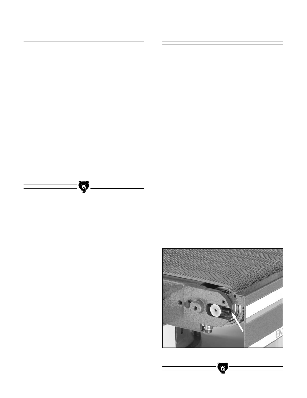
Feed Belt Tracking
To check the feed belt tracking:
1. Turn the feed belt ON.
2. If the belt moves to one side then you need
to immediately stop the machine and adjust
the belt tracking. If the belt tracks evenly,
leave it alone.
To adjust the feed belt tracking:
1. Unplug the sander!
2. Use the adjustment bolts (one is shown in
Figure 26) to correct the tracking.
3. Run the feed belt for a few minutes after the
adjustment to allow the belt to move into its
new position. When you are satisfied that the
belt has finished moving, stop the feed belt.
4. If more adjustments are necessary, experi-
ment with how the movement of the adjustment bolts affects the belt tracking; do this
until you can make the feed belt track evenly. Make sure you did not loosen the belt during the tracking process. If you did, adjust
each side of one belt roller away from the
machine, as evenly as possible.
Figure 26. This is a feed belt adjustment bolt.
To adjust the feed belt tension:
1. Disconnect the sander from the power
source!
2. Move the emergency brake plate up and out
of the way.
3. Tension adjustments are made using the
bolts located on the left and right side of the
front conveyor roller as shown in
Figure 26
.
4. When tensioned properly you should not be
able to lift the belt off the conveyor surface or
slide it back and forth, and it should not slip.
5. Perform the “Feed Belt Tracking” instructions
to ensure that the tracking did not change
during tensioning.
Feed Belt Tension
Page 33

G9983 15" Open-End Wide-Belt Sander -31-
V-Belt Tension
The sanding belt is driven by two V-belts on the
Model G9983. The V-belts must have adequate
tension for proper power transmission. Proper
tension is usually achieved when the V-belts can
be deflected no more than 1" with moderate finger pressure at the midpoint between the widebelt pulleys and the motor pulleys. The large
cover on the right-hand side of the sander must
be removed to access the V-belts and the sanding motor.
Thread the nuts shown in Figure 27 down to
tighten the V-belts, or thread the nuts up to
loosen the V-belts.
Always inspect V-belts for damage or deterioration when adjusting for tension. Should
you find evidence of cracking, abrasion or
damage from wood chips or other foreign
materials, replace the belt immediately. Belt
breakage may lead to mechanical damage or
operator injury.
Figure 27. Turning these nuts allows you to
raise/lower the motor to adjust the V-belts.
Replacing V-Belts
Figure 28. Loosen the V-belt by using the
adjustment nuts.
Inspect the V-belts closely; if you see any glazing,
cracking or fraying, replace the belts. Always
replace the two V-belts at the same time for proper power transmission.
To replace the V-belts:
1. Disconnect sander from the power
source and shut off air pressure.
2. Loosen the top nut on the motor adjustment
bolt shown in Figure 28. Turn the bottom nut
counterclockwise to raise the motor (or pry
motor up with a scrap piece of wood) and
loosen the V-belts.
3. When V-belts are sufficiently loose, slide
them off of the motor pulley.
4. To remove the V-belts from the roller pulley,
the roller needs to be removed. Open the
left-hand access door and remove the platen
micro-adjust knob by loosening the setscrew
that secures the face. The plate underneath
the knob is secured to the casting by two
setscrews—remove these. Figure 29 shows
the knob and indicator plate removed from
the casting.
5. Remove the large cap screws, also shown in
Figure 29, to loosen the casting on the roller
shafts.
Page 34

-32- G9983 15" Open-End Wide-Belt Sander
NOTICE
New V-belts will often stretch after moderate use. Check frequently after installation.
Figure 29. Remove platen adjustment knob,
indicator plate, and large cap screws.
Figure 31. Remove this roller shaft nut located
behind right-hand access door.
Figure 30. Work the casting off the roller shafts.
Figure 32. Remove roller.
6. Work the casting off the roller shafts as
shown in Figure 30.
7. Open the right-hand access door and locate
the large nut shown in Figure 31 and remove
it with the box wrench included with the
machine.
8. Slide out the front roller shaft, as shown in
Figure 32, to get the V-belts off of the pulley.
9. Installation is the reverse of removal. If pos-
sible, have an assistant help you when
installing the V-belts and the roller. Also, an
assistant can be helpful on the other end of
the roller when tightening the nuts on the
roller shafts.
Page 35

G9983 15" Open-End Wide-Belt Sander -33-
Air System
If you ever determine that a component in
the air system is malfunctioning, DO NOT
operate the sander. Fix the problem before
resuming operation.
The air system is durable and reliable; however,
components do wear with age. If you suspect that
an item in your air system may be having prob-
lems, use the diagram on page 38 to follow all
lines and connections, and use the instructions
below to investigate.
• Carefully inspect all air lines for cracks, tears
or hardening. Replace faulty hoses.
• Check the air connections for leaks. A small
amount of water in a questionable area will
bubble if there is a leak.
• Make sure lines are not clogged. Remove a
questionable line and blow through it as a
test.
Platen Graphite
The graphite sheet on the platen will wear out
with use. Similar to the sanding belts, the graphite
sheet is considered a “consumable” item and is
not covered under the warranty. We recommend
keeping replacements in your inventory to avoid
downtime. To obtain replacements, use the part
number in the back of this manual for ordering.
To replace the graphite sheet:
1. Pull the platen from its bracket with the
included platen puller tool.
2. Remove the screws and hold-down bar that
secure the graphite sheet to the platen.
3. Install the new graphite sheet exactly the
reverse as removal. Make sure that the
graphite sheet is wrapped in the same direction as the old one.
Page 36

-34- G9983 15" Open-End Wide-Belt Sander
Replacing Brakes
Figure 33. Removing caliper to replace
brake pads.
The only regular maintenance to perform on the
brakes is to keep the rotor clean. This is a simple
process and can be performed by spraying both
sides of the rotor with automotive brake parts
cleaner. The brake rotor must be free and clean
of any dust, dirt, oil or moisture.
Eventually the brake pads will wear out. Checking
and replacing these is a simple project that can
be done in the shop, with the exception of having
the rotor resurfaced.
To check the brake pads:
1. Disconnect the sander from the power
source and remove the air pressure completely.
2. Remove the four screws that secure the
motor cover on the right-hand side of the
machine. This will allow you to access the
brake components.
3. The brake pads consist of a metal plate with
a composite pad. With a fine ruler, measure
the thickness of the composite pad only. If
one of the pads is below
1
⁄8" (approx. 3mm),
replace both.
To replace the brake pads:
1. Disconnect the sander from the power
source and remove the air pressure completely.
2. Remove the nuts from the two mounting
bolts. There are two snap rings on the
mounting pins behind the bracket. Remove
these.
3. Pull the mounting pins out of the caliper
bracket and remove the air line from the
caliper. The caliper should now be able to be
removed as in Figure 33.
4. The brake pads are secured to the caliper
with cap screws. One of these screws is easily accessible; the other can only be reached
by disassembling the brake caliper. Do this
and remove the cap screws to remove the
brake pads.
5. Remove the brake rotor and have it profes-
sionally resurfaced. For this, find a local
machinist or auto supply store that regularly
resurfaces brake rotors for automobiles. If
visible cracks are present in the brake rotor,
replace with a new one. Clean the rotor with
automotive brake cleaner to remove any oil
or dirt. Handle with a dry rag and install
exactly the reverse of removal.
6. Install new brake pads, mount the caliper
and reconnect the air line.
Page 37

G9983 15" Open-End Wide-Belt Sander -35-
Service Performed
Approximate Hours Of Use
Service Log
Date
Page 38

-36- G9983 15" Open-End Wide-Belt Sander
The following pages contain general machine
data, parts diagrams/lists, a troubleshooting guide
and Warranty/Return information for your Model
G9983 Wide-belt Sanders.
If you need parts or help in assembling your
machine, or if you need operational information,
we encourage you to call our Service
Department. Our trained service technicians will
be glad to help you.
If you have comments dealing specifically with
this manual, please write to our Bellingham,
Washington location using the address in Section
2: Introduction. The specifications, drawings, and
photographs illustrated in this manual represent
the Model G9983 as supplied when the manual
was prepared. However, due to Grizzly’s policy of
continuous improvement, changes may be made
at any time with no obligation on the part of
Grizzly. Whenever possible, though, we send
manual updates to all owners of a particular tool
or machine. Should you receive one, add the new
information to this manual and keep it for reference.
We have included some important safety measures that are essential to this machine’s operation. While most safety measures are generally
universal, Grizzly reminds you that each workshop is different and safety rules should be con-
sidered as they apply to your specific situation.
We recommend you keep a copy of our current
catalog for complete information regarding
Grizzly's warranty and return policy. If you need
additional technical information relating to this
machine, or if you need general assistance or
replacement parts, please contact the Service
Department listed in Section 3: Introduction.
Additional information sources are necessary to
realize the full potential of this machine. Trade
journals, woodworking magazines, and your local
library are good places to start.
SECTION 8: CLOSURE
The Model G9983 was specifically designed
for sanding wood. DO NOT MODIFY
AND/OR USE THIS MACHINE FOR ANY
OTHER PURPOSE. Modifications or improper use of this tool will void the warranty. If
you are confused about any aspect of this
machine, DO NOT use it until all your questions have been answered. Serious personal injury may occur.
Like all power tools, there is danger associated with the Model G9983 Wide-belt
Sander. Accidents are frequently caused by
lack of familiarity or failure to pay attention.
Use this tool with respect and caution to
lessen the possibility of operator injury. If
normal safety precautions are overlooked
or ignored, serious personal injury may
occur.
This equipment has the potential to create
flying debris which can cause severe eye
injury. Always wear safety glasses or goggles when operating equipment. Everyday
glasses or reading glasses only have
impact resistant lenses, they are not safety
glasses. Be certain the safety glasses you
wear meet the appropriate standards of the
American National Standards Institute
(ANSI).
Page 39

G9983 15" Open-End Wide-Belt Sander -37-
Customer Service #: (570) 546-9663 • To Order Call: (800) 523-4777 • Fax #: (800) 438-5901
MODEL G9983
15" OPEN-END WIDE-BELT SANDER
MACHINE DATA
SHEET
Design Type ..................................................................................Floor Model - Open End
Overall Dimensions:
Height ..................................................................................................................61
3
⁄4"
Width ........................................................................................................................35"
Depth ....................................................................................................................32
1
⁄2"
Shipping Weight ................................................................................................923 lbs.
Net Weight ........................................................................................................815 lbs.
Foot Print ......................................................................................................29 x 23
1
⁄2"
Crate Size ................................................................................35
1
⁄2" L x 37" W x 70" H
Capacities:
Maximum Board Width (in one pass) ......................................................................15"
Maximum Board Thickness ....................................................................................5
1
⁄2"
Minimum Board Length .......................................................................................... 12"
Surface Speed of Sanding Belt ....................................................................2050 FPM
Conveyor Feed Rate ..........................................................................13.1 & 16.4 FPM
Sanding Belt Size............................................................................................16" x 48"
Sanding Motor:
Horsepower............................................................................................................5 HP
Voltage ..................................................................................................................220V
Amps..........................................................................................................................30
RPM ......................................................................................................................1725
Phase ⁄ Cycle ..........................................................................................Single ⁄ 60 HZ
Power Transfer........................................................................................2 V-Belt Drive
Conveyor Motor:
Horsepower ..........................................................................................................
1
⁄4 HP
Voltage ..................................................................................................................220V
Amps ........................................................................................................................1.8
RPM ......................................................................................................................1725
Phase ⁄ Cycle ..........................................................................................Single ⁄ 60 HZ
Power Transfer ................................................................................Gear Box to Chain
General Construction:
Cabinet ..................................................................................................................Steel
Belt Drums ....................................................................................Rubber Infeed Drum
................................................................................................................Steel Outfeed
..............................................................................................Rubber Pressure Rollers
Features:
............................................................................................Independent Motor Control
............................................................................................Pneumatic Belt Tensioning
................................................................................................Pneumatic Belt Tracking
....................................................................................................................Load Meter
........................................................................................................Safety Shut-Off Bar
............................................................................................................Thickness Scale
......................................................................Disc Brake System for Emergency Stops
....................................................................................................................5" Dust Port
Specifications, while deemed accurate, are not guaranteed.
Page 40

-38- G9983 15" Open-End Wide-Belt Sander
Air System
Various functions on the Model G9983 are controlled through the air system. Since this is a complex network of hoses and valves, please take
some time to familiarize yourself with each item
so you can better understand your machine during adjustments.
The illustration below follows the air travel
through the machine to familiarize you with how it
works. Match the letters in the text with those in
the illustration to learn more about each function.
1. The air flows into the machine at the pres-
sure regulator (A). This should be adjusted to
75 PSI.
2. The solenoid valve (C) controls the brake
caliper (B) when signaled by the emergency
stop switch or the limit switches.
3. The switching valve (E) controls the vertical
cylinder (D) which raises/lowers the top roller
(M) to tighten/loosen the sanding belt.
4. The valve (G) controls the air flow volume
that goes to the air eye fork (F), which controls the belt oscillation return.
5. The diaphragm (H) actuates the switching
valve (I) depending on whether air is coming
from the eye fork (F) or the pressure regulator (A).
6. Switching valve (I) actuates the diaphragm
(J), which controls oscillation arm (K), which
in turn, moves eccentric shaft (L), which
makes top roller (M) shift back and forth to
control belt movement during operation.
7. Valve (O) controls the speed at which the
belt moves back and forth.
8. Knob (N) allows you to rotate the eccentric
shaft (L) to balance the oscillation timing so it
takes the belt the same amount of time to
move in one direction as it moves in the other
direction.
This is an illustration of the air control system.
M
N
F
O
D
E
F
J
B
C
L
K
I
H
P
G
Air Inlet
A
Page 41

G9983 15" Open-End Wide-Belt Sander -39-
Model G9983
Wiring Diagram—Main Hook Up Panel
220 Volt Single-Phase
220V POWER
R S T
TO BRAKING
SOLENOID VALVE
12 13 3 3 5 5 U2
2 3 5 6 8 9 10 11 14 15
TO BELT &
STOP SWITCHES
TO ELECTRICAL
SWITCH PANEL
TO FEED
MOTOR
V2
TO MAIN MOTOR
U1
V1
W1
13
NC
L3
T3
RESET
1.7
1.9
1.5
1.3
2.1
A(R.C.)
FN1853-39
14
NC
1L13L25
CN11
2T14T26
29
31
1L13L25
CN11
2T14T26
1L13L25
CN 25
2T14T26
2A FUSES
!
Disconnect power from machine
before performing any electrical
service. Failure to do this will result
in a shock hazard leading to injury
or death.
L3
T3
RESET
26
23
21
A(R.C.)
FN1853-39
13
NC
L3
T3
14
NC
Page 42

-40- G9983 15" Open-End Wide-Belt Sander
D
I
C
N
A
I
T
R
O
E
R
Model G9983
X1 X2
W
O
P
220 Volt Single Phase
Wiring Diagram -Control Panel
E
D
E
F
21
22
X2
X1
21
22
B
E
P
L
O
T
T
S
E
E
D
F
B
T
E
R
L
A
T
T
S
N
A
D
S
I
N
G
B
P
E
O
L
T
T
S
14 13
13 14
14 13
21 22
2 3 5 6 8 9 10 11 14 15
N
A
D
S
I
X2
X1
21
22
N
G
B
T
E
R
L
A
T
T
S
E
R
T
13 14
21 22
Disconnect power from machine
before performing any electrical
service. Failure to do this will result
in a shock hazard leading to injury
E
S
T
R
E
S
E
14 13
or death.
!
Page 43

G9983 15" Open-End Wide-Belt Sander -41-
BELT
LIMIT
SWITCH
Model G9983
Wiring Diagram - 220 Volt Single Phase
MAIN MOTOR
1
5
4
4
1
3
2
4
1
3
2
Starting 250VAC
Capacitor 800MFD
Running 350VAC
Capacitor 50UF-U
1
2
6
EMERGENCY STOP
LIMIT SWITCH
1
4
3
2
SOLENOID
VALVE
12 13 3 3 5 5 U2
V2
FEED BELT MOTOR
1
4
W2
5
2
3
6
U1
V1
W1
!
Disconnect power from machine
before performing any electrical
service. Failure to do this will result
in a shock hazard leading to injury
or death.
Page 44
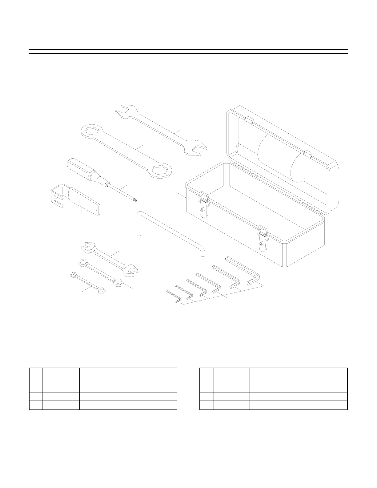
-42- G9983 15" Open-End Wide-Belt Sander
1 P9983001 TOOL BOX
2 PWR1214 COMBO WRENCH 12/14MM
3 P9983003 BOX WRENCH 30/37MM
4 P4000937 PHILLIPS SCREWDRIVER
5 P9983005 ACCESS DOOR HANDLE
6 PWR1719 COMBO WRENCH 17/19MM
7 PWR1113 COMBO WRENCH 11/13MM
8 PWR810 COMBO WRENCH 8/10MM
9 P9983009 ALLEN WRENCH SET (10)
10 P9983010 PLATEN TOOL
REF PART # DESCRIPTION REF PART # DESCRIPTION
G9983 Parts Breakdown
2
3
4
1
5
6
8
7
10
9
Page 45

G9983 15" Open-End Wide-Belt Sander -43-
124
110
109
111
108
106
120
119
107
105
118
113
126
121
122
125
117
115
114
103
104
102
116
123
101
154
153
134
155
132
133
130
158
157
129
131
156
135
160
144
159
161
143
146
145
137
136
127
147
142
138
149
148
139
150
141
140
151
128
152
112
Page 46

-44- G9983 15" Open-End Wide-Belt Sander
REF PART # DESCRIPTION
REF PART # DESCRIPTION
101 P9983101 MACHINE BASE
102 P9983102 QUILL BASE
103 PSB64M CAP SCREW M10-1.5 X 25
104 P9983104 LOCK WASHER 10MM
105 P9983105 LOCKING HANDLE
106 P9983106 WORM GEAR SHAFT
107 P51102 BEARING 51102
108 P6203 BEARING 6203ZZ
109 PR23M INT RETAINING RING 40MM
110 P9983110 HANDWHEEL
111 PSB64M CAP SCREW M10-1.5 X 25MM
112 P9983112 HANDLE M10
113 P9983113 WORM GEAR
114 P9983114 BUSHING
115 P9983115 GEAR SHAFT
116 PR18M EXT RETAINING RING 17MM
117 P9983117 QUILL
118 P9983118 RACK
119 PSB26M CAP SCREW M6-1.0 X 12
120 P9983120 CONVEYOR SUPPORT
121 PSB12M CAP SCREW M8-1.25 X 40
122 PLW04M LOCK WASHER 8MM
123 PSB12M CAP SCREW M8-1.25 X 40
124 P9983124 QUILL COVER
125 PS14M PHLP HD SCR M6-1.0 X 12
126 P9983126 FLAT WASHER 6MM
127 P9983127 MACHINE BASE COVER
128 PS47M PHLP HD SCR M6-1.0 X 25
129 P9983129 MOTOR BASE
130 P9983130 SETTING SHAFT
131 P9983131 LOCK BUSHING
132 PSS09M SETSCREW M8-1.25 X 20
133 PW04M FLAT WASHER 10MM
134 PSB62M CAP SCREW M10-1.5 X 12
135 P9983135 ADJUSTABLE SCREW
136 PW06M FLAT WASHER 12MM
137 PN09M HEX NUT M12-1.75
138 P9983138 BRAKE PIN
139 PR47M EXT RETAINING RING 13MM
140 PLW06M LOCK WASHER 10MM
141 PN02M HEX NUT M10-1.5
142 P9983142 BRAKE CALIPER
143 P9983143 BRAKE PAD
144 PS14M CAP SCREW M6-1.0 X 12
145 P9983145 SPRING
146 P9983146 BRAKE AXLE
147 P9983147 PLATE
148 PS47M PHLP HD SCR M6-1.0 X 25
149 P9983149 DIAPHRAGM
150 P9983150 TOP COVER
151 PS20M PHLP HD SCR M5-.08 X 15
152 P9983152 PLASTIC CONNECTOR
153 PLW06M LOCK WASHER 10MM
154 PB01M HEX BOLT M10-1.5 X 30
155 P9983155 SPINDLE MOTOR 5HP
156 P9983156 BRAKE ROTOR
157 PLW06M LOCK WASHER 10MM
158 PSB75M CAP SCREW M10-1.5 X 18
159 P9983159 MOTOR PULLEY
160 PSS13M SETSCREW M10-1.5 X 12
161 PVA71 BELT A71
Page 47

G9983 15" Open-End Wide-Belt Sander -45-
225
REF PART # DESCRIPTION
REF PART # DESCRIPTION
201 P9983201 CONVEYOR SUPPORT
202 P9983202 ROLLER BRACKET LH
203 P9983203 ROLLER BRACKET RH
204 PLW04M LOCK WASHER 8MM
205 PB07M HEX BOLT M8-1.25 X 25
206 PSB40M CAP SCREW M8-1.25 X 35
207 P9983207 BRASS ROLLER
208 PLW04M LOCK WASHER 8MM
209 PN03M HEX NUT M8-1.25
210 P9983210 LIMIT SWITCH BASE
211 PW03M FLAT WASHER 6MM
212 PS14M PHLP HD SCR M6-1.0 X 12
213 P9983213 LIMIT SWITCH
214 PW05M FLAT WASHER 4MM
215 PS48M PHLP HD SCR M4-.7 X 50
216 PN04M HEX NUT M4-.7
217 P9983217 E-BRAKE PANEL
218 PRP03M PIN 5 X 20MM
219 PR11M EXT RETAINING RING 25MM
220 P6305 BEARING 6305ZZ
221 P9983221 CONVEYOR AXLE
222 PSS39M SETSCREW M10-1.5 X 50
223 P9983223 CONVEYOR ROLLER
224 P9983224 CONVEYOR BELT 380 X 1600
225 P9983225 BEARING SEAT
226 PLW04M LOCK WASHER 8MM
227 PB09M HEX BOLT M8-1.25 X 20
228 P6204 BEARING 6204ZZ
229 PR25M INT RETAINING RING 47MM
230 P9983230 MAIN ROLLER
231 PK67M KEY 8 X 7 X 15MM
232 P9983232 MOTOR PANEL
233 P6205 BEARING 6205ZZ
234 PR11M EXT RETAINING RING 25MM
235 P9983235 BEARING COVER
236 PSB74M CAP SCREW M6-1.0 X 18
237 P9983237 BUSHING
238 P9983238 CHAIN WHEEL 19T X 24T
239 PSS02M SETSCREW M6-1.0 X 6
240 P9983240 CHAIN
3
⁄
8" X 48PC
241 P9983241 ROLLER CHAIN COVER
242 PSB37M CAP SCREW M6-1.0 X 50
243 P9983243 FEED MOTOR
1
⁄4 HP
244 PLW04M LOCK WASHER 8MM
245 PN03M HEX NUT M8-1.25
246 PW01M FLAT WASHER 8MM
247 PB26M HEX BOLT M8-1.25 X 30
248 PLW04M LOCK WASHER 8MM
249 PB09M HEX BOLT M8-1.25 X 20
250 P9983250 CHAIN WHEEL 12T, 14T
251 PSS02M SETSCREW M6-1.0 X 6
228
229
230
231
232
233
245
243
244
235
234
237
236
246
247
239
251
248
238
250
249
242
241
240
209
208
210
201
207
227
226
205
202
204
218
206
215
214
203
223
213
219
216
211
212
220
221
222
217
224
Page 48
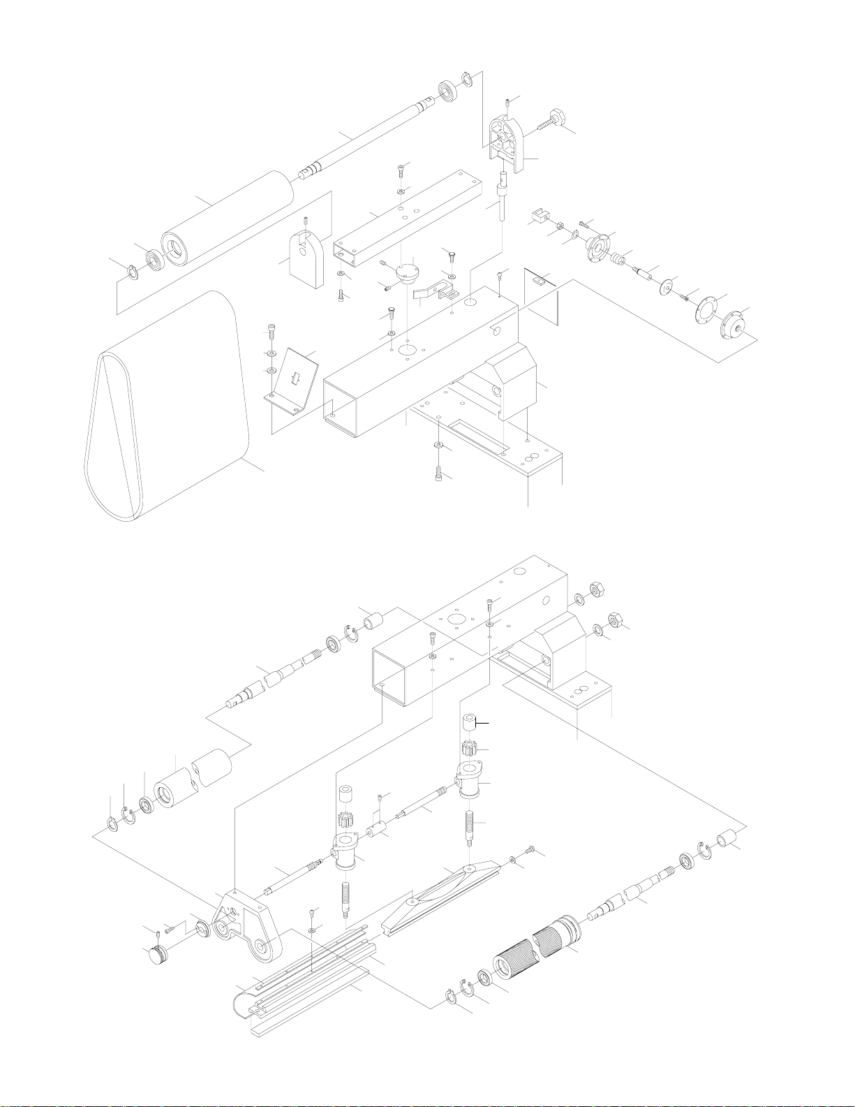
-46- G9983 15" Open-End Wide-Belt Sander
324
G9983
327
328
329
307
306
305
320
381
330
304
317
316
321
322
311
310
319
318
315
312
314
313
326
302
303
341
309
323
340
339
308
301
325
338
337
336
335
334
333
332
331
349
348
350
358
357
356
351
355
354
374
352
375
359
377
376
353
363
378
361
360
373
362
370
342
368
367
366
365
364
369
343
344
371
372
380
379
347
346
345
Page 49

G9983 15" Open-End Wide-Belt Sander -47-
REF PART # DESCRIPTION
REF PART # DESCRIPTION
301 P9983301 CONTACT ROLLER BASE
302 PLW06M LOCK WASHER 10MM
303 PSB72M CAP SCREW M10-1.5 X 30
304 P9983304 SWITCH PLATE
306 PLW06M LOCK WASHER 10MM
307 PSB72M CAP SCREW M10-1.5 X 30
308 P9983308 COVER
309 PS02M PHLP HD SCR M4-.07 X 12
310 PLW04M LOCK WASHER 8MM
311 PB07M HEX BOLT M8-1.25 X 25
312 P9983312 FORK
313 PW03M FLAT WASHER 6MM
314 PS14M PHLP HD SCR M6-1.0 X 12
315 P9983315 CYLINDER ROLLER FRAME
316 PSS04M SETSCREW M6-1.0 X 12
317 P9983317 SUPPORT TUBE
318 PLW04M LOCK WASHER 8MM
319 PSB76M CAP SCREW M8-1.25 X 18
320 P9983320 TOP ROLLER SUPPORT
321 PLW04M LOCK WASHER 8MM
322 PSS41M SETSCREW M8-1.25 X 18
323 P9983323 TOP ECCENTRIC FRAME
324 PSB26M CAP M6-1.0 X 12MM
325 P9983325 KNOB BOLT M8 X 55
326 P9983326 ECCENTRIC SHAFT
327 PR11M EXT RETAINING RING 25MM
328 P6205 BEARING 6205ZZ
329 P9983329 TOP ROLLER
330 P9983330 TOP ROLLER SHAFT
331 P9983331 TOP COVER
332 P9983332 DIAPHRAGM
333 PS14M PHLP HD SCR M6-1.0 X 12
334 P9983334 PLATE
335 P9983335 SHAFT
336 P9983336 SPRING
337 P9983337 BOTTOM COVER
338 PS06M PHLP HD SCR M5-.8 X 20
339 PR05M EXT RETAINING RING 15MM
340 PN02M HEX NUT M10-1.5
341 P9983341 OSCILLATION SQUARE
342 PR11M EXT RETAINING RING 25MM
343 PR25M INT RETAINING RING 47MM
344 P6005 BEARING 6005ZZ
345 P9983345 CONTACT ROLLER
346 P9983346 ROLLER SHAFT
347 P9983347 SLEEVE
348 PR11M RETAINING RING S25
349 PR25M RETAINING RING R47
350 P6005 BEARING 6005ZZ
351 P9983351 SUPPORT ROLLER
352 P9983352 ROLLER SHAFT
353 P9983353 BUSHING
354 P9983354 ROLLER BASE
355 P9983355 MICROMETER BASE
356 PSB26M CAP SCREW M6-1.0 X 12
357 P9983357 MICROMETER
358 PSS04M SETSCREW M6-1.0 X 12
359 P9983359 MAIN WORM GEAR SHAFT
360 P9983360 CONNECTION COUPLING
361 PSS04M SETSCREW M6-1.0 X 12
362 P9983362 SUPP WORM GEAR SHAFT
363 P9983363 GRAPHITE BASE L
364 P9983364 GRAPHITE BASE R
365 P9983365 WORM GEAR
366 P9983366 GEAR BUSHING
367 PLW04M LOCK WASHER 8MM
368 PB03M HEX BOLT M8-1.25 X 16
369 P9983369 VERT MICROMETER SCREW
370 P9983370 PLATEN (MALE)
371 PW01M FLAT WASHER 8MM
372 PSB58M CAP SCREW M8-1.25 X 12
373 P9983373 PLATEN (FEMALE)
374 P9983374 CARBON GRAPHITE
375 P9983375 SET PLATE
376 PW05M FLAT WASHER 4MM
377 PS02M PHLP HD SCR M4-.7 X 12
378 P9983378 LINING 30 X 415MM
379 PLW07M LOCK WASHER 20MM
380 PN17M HEX NUT M20-1.5
381 P9983381 SANDING BELT 16"W X 48"
Page 50
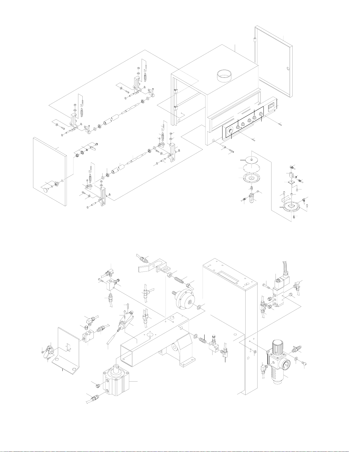
-48- G9983 15" Open-End Wide-Belt Sander
404
403
404
415
414
413
424
423
425
426
416
422
418
417
421
420
419
412
427
428
401
410
440
441
442
408
443
446
409
411
407
445
444
433
438
437
402
405
406
411
430
429
431
435
436
432
434
439
502
503
501
504
506
505
501
540
539
515
513
507
514
508
511
510
512
517
509
538
518
516
519
520
521
523
522
524
525
532
531
534
526
527
528
530
529
535
536
537
533
Page 51

G9983 15" Open-End Wide-Belt Sander -49-
REF PART # DESCRIPTION
REF PART # DESCRIPTION
401 P9983401 MACHINE FRAME
402 P9983402 ACCESS DOOR RH
403 P9983403 ACCESS DOOR LH
404 P9983404 LOCK
405 P9983405 OPERATING PANEL
406 P9983406 LOAD METER
407 P9983407 POWER INDICATOR
408 P9983408 START BUTTON
409 P9983409 STOP BUTTON
410 P9983410 EMERGENCY STOP BUTTON
411 PS47M PHLP HD SCR M6-1.0 X 25
412 P9983412 PRESSURE ROLLER FRAME
413 PLW03M LOCK WASHER 6MM
414 PSB06M CAP SCREW M6-1.0 X 25
415 P9983415 TILTING ARM
416 PSS26M SETSCREW M5-08 X 6
417 P9983417 SPRING
418 P9983418 SPRING HOOK
419 PW01M FLAT WASHER 8MM
420 PN03M HEX NUT M8
421 P9983421 SET PIN
422 PR01M EXT RETAINING RING 10MM
423 P9983423 BEARING COVER
424 P6001 BEARING 6001ZZ
425 P9983425 PRESSURE ROLLER
426 P9983426 PRESSURE SHAFT
427 P9983427 SPECIAL NUT M8-1.25
428 PSS42M SETSCREW M8-1.25 X 50
429 P9983429 PLASTIC CONNECTOR L6-
1
⁄8"
430 P9983430 SWITCHING VALVE
1
⁄8"
431 P9983431 SILENCER
1
⁄8"
432 P9983432 PLASTIC CONNECTOR C6-
1
⁄8"
433 P9983433 LINING
434 PS49M PHLP HD SCR M3-.5 X 5
436 PS02M PHLP HD SCR M4-.7 X 12
437 P9983437 TOP ALUMINUM COVER
438 PS06M PHLP HD SCR M5-.8 X 20
439 P9983439 PLASTIC CONNECT M6 X
1
⁄4"
440 P9983440 PLATE
441 P9983441 DIAPHRAGM
442 P9983442 BOTTOM ALUMINUM COVER
443 P9983443 PLASTIC CONNECT
1
⁄8" X 1⁄8"
444 P9983444 CUP
1
⁄4"
445 P9983445 CONNECTOR 1⁄4"
446 P9983446 PLASTIC CONNECT C6-
1
⁄4"
501 P9983501 SWITCHING VALVE
502 PS12M PHLP HD SCR M3-.5 X 6
503 PS12M PHLP HD SCR M3-.5 X 6
504 P9983504 LIMIT SWITCH PANEL
505 P9983505 SILENCER
1
⁄8"
506 P9983506 PLASTIC CONNECT L6-
1
⁄8"
507 P9983507 PLASTIC CONNECT C6-
1
⁄8"
508 P9983508 SENSOR PIN
509 P9983509 LIMIT SWITCH 8166
510 PS50M PHLP HD SCR M3-.5 X 12
511 PS50M PHLP HD SCR M3-.5 X 12
512 P9983512 AIR VALVE
1
⁄8"
513 P9983513 PLASTIC CONNECT C6-
1
⁄8"
514 P9983514 PLASTIC CONNECT L6-
1
⁄8"
515 PS52M PHLP HD SCR M4-.7 X 20
516 P9983516 PLASTIC CONNECT 6Y
517 P9983517 PLASTIC CONNECT 6T
518 P9983518 PLASTIC CONNECT C6-
1
⁄8"
519 PN11 HEX NUT
3
⁄8"-24
520 P9983520 AIR EYELET (OUT)
3
⁄8"
521 P9983521 BRASS NUT
3
⁄8"-UNF
522 P9983522 BUSHING 10MM
523 P9983523 PLASTIC CONNECT
1
⁄8" X 3⁄8"
524 P9983524 AIR VALVE
1
⁄8
"
525 P9983525 PLASTIC CONNECT L6-
1
⁄8"
526 P9983526 SOLENOID VALVE
1
⁄8" X 220V
527 P9983527 PLASTIC CONNECT B6-
1
⁄8
"
528 P9983528 PLASTIC CONNECT L6-
1
⁄8"
529 P9983529 SILENCER
1
⁄8"
530 P9983530 CONNECTOR
531 PS25M PHLP HD SCR M4-.7 X 35
532 PN04M HEX NUT M4-.7
533 P9983533 PRESSURE GAUGE
K-1000FR2
534 P9983534 PLASTIC CONNECT L6-1⁄4"
535 P9983535 AIR COCK
1
⁄4" X 5⁄16"
536 PW03M FLAT WASHER 6MM
537 PS14M PHLP HD SCR M6-1.0 X 12
538 P9983538 TENSION CYLINDER
63 X 40ST
539 P9983539 PLASTIC CONNECT C6-1⁄8"
540 P9983540 SILENCER
1
⁄4"
Page 52

-50- G9983 15" Open-End Wide-Belt Sander
620
619
621
622
601
623
618
624
625
608
609
603
617
604
626
612
612
606
611
605
606-1
604-1
602
601
602
717
713
718*
728*
715
714
720*
719*
729*
721*
722*
726*
711
706
707
704
703
702
701
* Optional Parts
705
710
712
708
709
716
725*
724*
723*
730*
731
727
Page 53

G9983 15" Open-End Wide-Belt Sander -51-
REF PART # DESCRIPTION
REF PART # DESCRIPTION
601 P9983601 CONTROL BOX
602 P9983602 LOCK
603 P9983603 CONTROL PANEL
604 P9983604 CONTACTOR CN-25 SAND
604-1 P9983604-1 THERMAL RH 18/26
605 P9983605 CONTACTOR CN-11 MAIN
606 P9983606 CONTACTOR CN-11 FEED
606-1 P9983606-1 THERMAL RH 10E/1.7C
608 P9983608 CURRENT TRANSFORMER
609 P9983609 TERMINAL BOARD
611 P9983611 TERMINAL BOARD
612 P9983612 TERMINAL BOARD
617 P9983617 GROUND WIRE PANEL
618 P9983618 WIRE SLEEVE
619 P9983619 WIRE SLEEVE
620 P9983620 WIRE SLEEVE
621 P9983621 WIRE SLEEVE
622 P9983622 WIRE SLEEVE
623 P9983623 WIRE SLEEVE
624 P9983624 WIRE CONNECTOR (IN)
625 PS14M PHLP HD SCR M6-1.0 X 12
626 PN01M HEX NUT M6-1.0
701 P9983701 PLASTIC COVER
702 PN03M HEX NUT M8-1.25
703 PLW04M LOCK WASHER 8MM
704 PW01M FLAT WASHER 8MM
705 P9983705 TABLE SUPPORT
706 P9983706 SUPPORT LINING
707 PS11M PHLP HD SCR M6-1.0 X 16
708 PW03M FLAT WASHER 6MM
709 PN01M HEX NUT M6-1.0
710 P9983710 RETRACTABLE ROD
711 PSS10M SETSCREW M10-1.5 X 20
712 PN02M HEX NUT M10-1.5
713 P9983713 ECCENTRIC SHAFT LH
714 PN27M HEX NUT LH M10-1.5
715 PLW06M LOCK WASHER 10MM
716 P9983716 ECCENTRIC SHAFT RH
717 PN02M HEX NUT M10-1.5
718 PSB62M CAP SCREW M10-1.5 X 12
719 PLW06M LOCK WASHER 10MM
720 PW04M FLAT WASHER 10MM
721 P9983721 INFEED TABLE FRAME
722 PR47M EXT RETAINING RING 13MM
723 P9983723 ROLLER BUSHING
724 P9983724 ROLLER SHAFT
725 P9983725 CONVEYOR ROLLER
726 PRP28M PIN 5 X 40MM
727 P9983727 EMERGENCY BRAKE PANEL
728 P9983728 KNOB
729 P9983729 BRAKE ROD
730 PR39M EXT RETAINING RING 8MM
731 P9983731 SPRING
Page 54

-52- G9983 15" Open-End Wide-Belt Sander
For your safety, turn switch OFF and disconnect the machine from power source
before any troubleshooting. Please refer to
the adjustment section to make corrections.
TROUBLESHOOTING
SYMPTOM
Motor will not start.
Motor will not start; fuses or
circuit breakers blow.
Motor overheats.
Motor stalls (resulting in
blown fuses or tripped circuit).
Machine slows when operating.
Loud, repetitious noise coming from machine
Machine is loud, overheats
or bogs down in the cut.
Edges of wood are rounded.
Uneven thickness from left
to right of board.
Workpiece slips on feed
belt.
Straight strip of notches on
workpiece.
Snake shaped marks on
workpiece.
POSSIBLE CAUSE
1. Low voltage.
2. Open circuit in motor or loose connections.
1. Short circuit in line cord or plug.
2. Short circuit in motor or loose connections.
3. Incorrect fuses or circuit breakers
in power line.
1. Motor overloaded.
2. Air circulation through the motor
restricted.
1. Short circuit in motor or loose connections.
2. Low voltage.
3. Incorrect fuses or circuit breakers
in power line.
4. Motor overloaded.
1. Feed rate too high.
2. Depth of cut too great.
1. Pulley set screws or keys are missing or loose.
2. Motor fan is hitting the cover.
3. V-belt is defective.
1. Excessive depth of cut.
2. Dull sanding belt.
1. Excessive depth of cut.
1. Feed table not parallel to sanding
roller.
2. Feed belt is worn.
1. Pressure rollers set too high.
2. Dirty feed belt.
3. Feed belt is worn.
1. Pressure rollers are dirty or damaged.
1. Sanding belt damaged or dirty.
CORRECTIVE ACTION
1. Check power line for proper voltage.
2. Inspect all lead connections on motor for loose or open connections.
1. Inspect cord or plug for damaged insulation and shorted wires.
2. Inspect all connections on motor for loose or shorted terminals or
worn insulation.
3. Install correct fuses or circuit breakers.
1. Reduce load on motor.
2. Clean out motor to provide normal air circulation.
1. Inspect connections on motor for loose or shorted terminals or worn
insulation.
2 Correct the low voltage conditions.
3. Install correct fuses or circuit breakers.
4. Reduce load on motor.
1. Feed workpiece slower and watch load meter.
2. Reduce depth of cut and watch load meter.
1. Inspect keys and set screws. Replace or tighten if necessary.
2. Tighten fan or shim cover.
3. Replace V-belt. See Maintenance section.
1. Decrease depth of cut.
2. Replace sanding belt.
1. Reduce depth of cut.
1. Adjust the table.
2. Replace feed belt.
1. Lower pressure rollers.
2. Clean feed belt.
3. Replace feed belt.
1. Clean or repair pressure rollers.
1. Clean or replace sanding belt.
Page 55

G9983 15" Open-End Wide-Belt Sander -53-
For your safety, turn switch OFF and disconnect the machine from power source
before any troubleshooting. Please refer to
the adjustment section to make corrections.
TROUBLESHOOTING
SYMPTOM
Lines across width of workpiece.
More material is removed
from the end of workpiece
than the length (snipe).
Glossy spots or streaks on
workpiece.
Sanding belt clogs quickly.
Sanding belt does not tension correctly; rollers slip
under belt.
Sanding belt runs off to one
side, stopping the sander.
Sanding belt will not start.
Poor, non-aggressive sanding results.
Conveyor belt not tracking
in center.
Conveyor belt slipping.
Emergency brake stops
slow.
Grinding noise when braking.
POSSIBLE CAUSE
1. Sanding belt seam is open or damaged.
1. Workpiece is not supported as it
comes out of sander.
2. Pressure rollers not set correctly.
1. Worn sanding belt.
2. Rear pressure roller too low.
1. Sanding belt grit too small for particular job.
2. Excessive depth of cut.
3. Wood is too moist.
1. Low air pressure.
2. Air leaks in system.
1. Air eye fork clogged.
2. Oscillation return valve closed.
3. Oscillation timing incorrect.
1. Sanding belt is not tensioned.
2. Limit switches engaged.
3. Emergency stop plate engaged.
1. Platen adjusted incorrectly, above
bottom surface level of lower sanding rollers.
2. Sanding belt loaded with sawdust.
3. Sanding belt worn out.
1. Conveyor rollers moved out of
adjustment.
1. Conveyor rollers have incorrect
tension.
2. Conveyor rollers contaminated with
dirt or dust.
1. Air pressure incorrect.
2. Air leak in system.
3. Brake rotor contaminated with oil.
4. Brake pads worn out.
1. Brakes severely worn out.
CORRECTIVE ACTION
1. Repair or replace sanding belt.
1. Hold workpiece up with your hands as it comes out, or set up an outfeed table for your workpiece after it comes out.
2. Set pressure rollers as described in Section 8: Service Adjustments.
1. Replace sanding belt.
2. Raise rear pressure roller. (See warning in Pressure Roller sec-
tion!)
1. Replace with a coarser grit sanding belt.
2. Reduce depth of cut.
3. Allow wood to dry out.
1. Adjust air pressure to 75 PSI at primary regulator.
2. Inspect all hoses and connections for leaking air; use water on suspected area to detect bubbles.
1. Clean the intake hole on the air eye fork.
2. Open valve.
3. Adjust oscillation timing.
1. Tension sanding belt.
2. Center sanding belt so it is not touching the limit switches.
3. Make sure emergency stop switch is released.
1. Adjust platen on the same plane as, or lower than, bottom surface
level of lower rollers.
2. Clean sanding belt to unload sawdust.
3. Replace sanding belt with a new one.
1. Re-adjust conveyor rollers.
1. Adjust conveyor rollers to increase tension.
2. Clean conveyor rollers.
1. Adjust air pressure to 75 PSI.
2. Find and fix air leaks.
3. Clean brake rotor with automotive brake parts cleaner.
4. Replace brake pads.
1. Replace brake pads, have rotor turned (possibly replaced).
Page 56

-54- G9983 15" Open-End Wide-Belt Sander
WARRANTY AND RETURNS
Grizzly Industrial, Inc. warrants every product it sells for a period of 1 year to the original purchaser from
the date of purchase. This warranty does not apply to defects due directly or indirectly to misuse, abuse,
negligence, accidents, repairs or alterations or lack of maintenance. This is Grizzly’s sole written warranty
and any and all warranties that may be implied by law, including any merchantability or fitness, for any particular purpose, are hereby limited to the duration of this written warranty. We do not warrant or represent
that the merchandise complies with the provisions of any law or acts unless the manufacturer so warrants.
In no event shall Grizzly’s liability under this warranty exceed the purchase price paid for the product and
any legal actions brought against Grizzly shall be tried in the State of Washington, County of Whatcom.
We shall in no event be liable for death, injuries to persons or property or for incidental, contingent, special, or consequential damages arising from the use of our products.
To take advantage of this warranty, contact us by mail or phone and give us all the details. We will then
issue you a “Return Number,’’ which must be clearly posted on the outside as well as the inside of the carton. We will not accept any item back without this number. Proof of purchase must accompany the merchandise.
The manufacturers reserve the right to change specifications at any time because they constantly strive to
achieve better quality equipment. We make every effort to ensure that our products meet high quality and
durability standards and we hope you never need to use this warranty.
Please feel free to write or call us if you have any questions about the machine or the manual.
Thank you again for your business and continued support. We hope to serve you again soon.
Page 57

G9983 15" Open-End Wide-Belt Sander -55-
10. Which benchtop tools do you own? Check all that apply.
___1" x 42" Belt Sander ___6" - 8" Grinder
___5" - 8" Drill Press ___Mini Lathe
___8" Table Saw ___10" - 12" Thickness Planer
___8" - 10" Bandsaw ___Scroll Saw
___Disc/Belt Sander ___Spindle/Belt Sander
___Mini Jointer
___Other__________________________________________________
11. How many of the machines checked above are Grizzly? ____________
12. Which portable/hand held power tools do you own? Check all that apply.
___Belt Sander ___Orbital Sander
___Biscuit Joiner ___Palm Sander
___Circular Saw ___Portable Planer
___Detail Sander ___Saber Saw
___Drill/Driver ___Reciprocating Saw
___Miter Saw ___Router
___Other__________________________________________________
13. What machines/supplies would you like Grizzly Industrial to carry?
__________________________________________________________
__________________________________________________________
__________________________________________________________
14. What new accessories would you like Grizzly Industrial to carry?
__________________________________________________________
__________________________________________________________
__________________________________________________________
15. What other companies do you purchase your tools and supplies from?
__________________________________________________________
__________________________________________________________
16. Do you think your purchase represents good value?
___Yes ___No
17. Would you recommend Grizzly Imports to a friend?
___Yes ___No
18. Would you allow us to use your name as a reference for Grizzly customers
in your area? Note: We never use names more than three times.
___Yes ___No
19. Comments:_________________________________________________
__________________________________________________________
__________________________________________________________
__________________________________________________________
__________________________________________________________
1. How did you learn about us?
___Advertisement ___Friend
___Catalog ___Card Deck
___World Wide Web
___Other__________________________________________________
2. Which of the following magazines do you subscribe to.
___American Woodworker ___Practical Homeowner
___Cabinetmaker ___Shop Notes
___Family Handyman ___Today’s Homeowner
___Fine Homebuilding ___WOOD
___Fine Woodworking ___WoodenBoat
___Home Handyman ___Woodshop News
___Journal of Light Construction ___Woodsmith
___Old House Journal ___Woodwork
___Popular Mechanics ___Woodworker
___Popular Science ___Woodworker’s Journal
___Popular Woodworking ___Workbench
___Other__________________________________________________
3. Which of the following woodworking/remodeling shows do you watch?
___Backyard America ___The New Yankee Workshop
___Home Time ___This Old House
___The American Woodworker ___Woodwright’s Shop
___Other__________________________________________________
4. What is your annual household income?
___$20,000-$29,999 ___$60,000-$69,999
___$30,000-$39,999 ___$70,000-$79,999
___$40,000-$49,999 ___$80,000-$89,999
___$50,000-$59,999 ___$90,000 +
5. What is your age group?
___20-29 ___50-59
___30-39 ___60-69
___40-49 ___70 +
6. How long have you been a woodworker?
___0 - 2 Years ___8 - 20 Years
___2 - 8 Years ___20+ Years
7. How would you rank your woodworking skills?
___Simple ___Advanced
___Intermediate ___Master Craftsman
8. What stationary woodworking tools do you own? Check all that apply.
___Air Compressor ___Panel Saw
___Band Saw ___Planer
___Drill Press ___Power Feeder
___Wide-belt Sander ___Radial Arm Saw
___Dust Collector ___Shaper
___Horizontal Boring Machine ___Spindle Sander
___Jointer ___Table Saw
___Lathe ___Vacuum Veneer Press
___Mortiser ___Wide Belt Sander
___Other__________________________________________________
9. How many of your woodworking machines are Grizzly? _____________
Name ____________________________________________________________________________________
Street ____________________________________________________________________________________
City ______________________________________________________________State________Zip_________
Phone Number_______________________E-Mail_______________________FAX________________________
MODEL #____________________Serial#_______________________Order#_____________________________
The following information is given on a voluntary basis. It will be used for marketing purposes to help us develop better products and services. Of course,
all information is strictly confidential.
WARRANTY CARD
CUT ALONG DOTTED LINE
Page 58

FOLD ALONG DOTTED LINE
FOLD ALONG DOTTED LINE
GRIZZLY INDUSTRIAL, INC.
P.O. BOX 2069
BELLINGHAM, WA 98227-2069
Place
Stamp
Here
TAPE ALONG EDGES--PLEASE DO NOT STAPLE
Name_______________________________
Street_______________________________
City______________State______Zip______
Send a Grizzly Catalog to a friend:
Page 59

Page 60

Buy Direct and Save with Grizzly® – Trusted, Proven and a Great Value!
Visit Our Website Today And Discover Why
Grizzly® Is The Industry Leader!
• SECURE ORDERING
• ORDERS SHIPPED WITHIN 24 HOURS
• E-MAIL RESPONSE WITHIN ONE HOUR
-OR-
Call Today For A
Full Color Catalog
FREE
 Loading...