

Page 1
COPYRIGHT © JUNE, 2003 BY GRIZZLY INDUSTRIAL, INC.
WARNING: NO PORTION OF THIS MANUAL MAY BE REPRODUCED IN ANY SHAPE
OR FORM WITHOUT THE WRITTEN APPROVAL OF GRIZZLY INDUSTRIAL, INC.
PRINTED IN CHINA
ONLINE MANUAL DISCLAIMER
THE INFORMATION IN THIS MANUAL REPRESENTS THE CONFIGURATION OF THE MACHINE AS IT IS CURRENTLY BEING SHIPPED. THE MACHINE
CONFIGURATION CAN CHANGE AS PRODUCT IMPROVEMENTS ARE INCORPORATED. IF YOU OWN AN EARLIER VERSION OF THE MACHINE, THIS
MANUAL MAY NOT EXACTLY DEPICT YOUR MACHINE . CONTACT CUSTOMER SERVICE IF YOU HAVE ANY QUESTIONS ABOUT DIFFERENCES.
PREVIOUS VERSIONS ARE NOT AVAILABLE ONLINE.
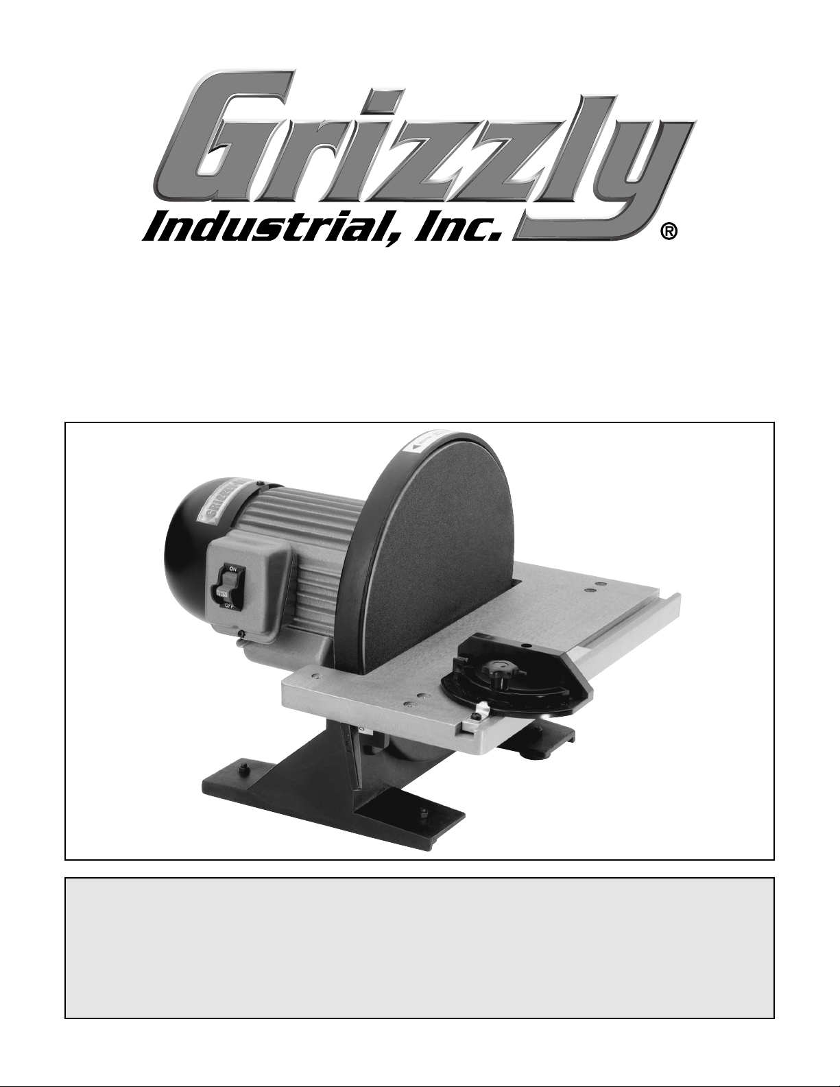
12" DISC SANDER
MODEL G7297
INSTRUCTION MANUAL
Page 2

WARNING
Some dust created by power sanding, sawing, grinding, drilling, and other construction activities contains
chemicals known to the State of California to cause
cancer, birth defects or other reproductive harm.
Some examples of these chemicals are:
• Lead from lead-based paints.
• Crystalline silica from bricks, cement, and
other masonry products.
• Arsenic and chromium from chemically treated
lumber.
Your risk from these exposures varies, depending on
how often you do this type of work. To reduce your
exposure to these chemicals: work in a well ventilated area, and work with approved safety equipment,
such as those dust masks that are specially
designed to filter out microscopic particles.
Page 3

TABLE OF CONTENTS
SECTION 1: SAFETY ..............................................................................................2
Safety Instructions for Power Tools ....................................................................2
Additional Safety Instructions for Sanders ..........................................................4
SECTION 2: INTRODUCTION ..................................................................................5
SECTION 3: CIRCUIT REQUIREMENTS ................................................................6
110 Volt Operation ..............................................................................................6
Grounding ............................................................................................................7
Extension Cords ..................................................................................................7
SECTION 4: IDENTIFICATION ................................................................................8
SECTION 5: SET UP ................................................................................................9
G7297 Inventory ..................................................................................................9
Unpacking ............................................................................................................9
Site Considerations............................................................................................10
SECTION 6: ADJUSTMENTS ................................................................................11
Table Tilt ............................................................................................................11
Miter Gauge ......................................................................................................12
Attaching Sandpaper ........................................................................................12
Aligning Table ....................................................................................................13
SECTION 7: OPERATIONS....................................................................................14
Disc Sanding......................................................................................................14
Miter Sanding ....................................................................................................15
Angle Sanding....................................................................................................15
SECTION 8: MAINTENANCE ................................................................................16
Maintenance Safety ..........................................................................................16
Schedule ............................................................................................................16
SECTION 9: REFERENCE INFO............................................................................17
Aftermarket Accessories....................................................................................17
Troubleshooting Guide ......................................................................................18
Machine Data Sheet ..........................................................................................19
Parts Diagrams and Lists ..................................................................................20
Warranty and Returns........................................................................................22
Page 4
-2-
G7297 Disc Sander
5. KEEP CHILDREN AND VISITORS
AWAY. All children and visitors should be
kept at a safe distance from work area.
6. MAKE WORKSHOP CHILD PROOF with
padlocks, master switches, or by removing
starter keys.
7. NEVER FORCE TOOL. It will do the job
better and safer at the rate for which it was
designed.
8. USE THE RIGHT TOOL. DO NOT force
the tool or attachment to do a job for which
it was not designed.
1. KEEP GUARDS IN PLACE and in working
order.
2. REMOVE ADJUSTING KEYS AND
WRENCHES. Form habit of checking to
see that keys and adjusting wrenches are
removed from tool before turning on.
3. KEEP WORK AREA CLEAN. Cluttered
areas and benches invite accidents.
4. NEVER USE IN DANGEROUS ENVIRONMENT. DO NOT use power tools in
damp or wet locations, or where any flammable or noxious fumes may exist. Keep
work area well lighted.
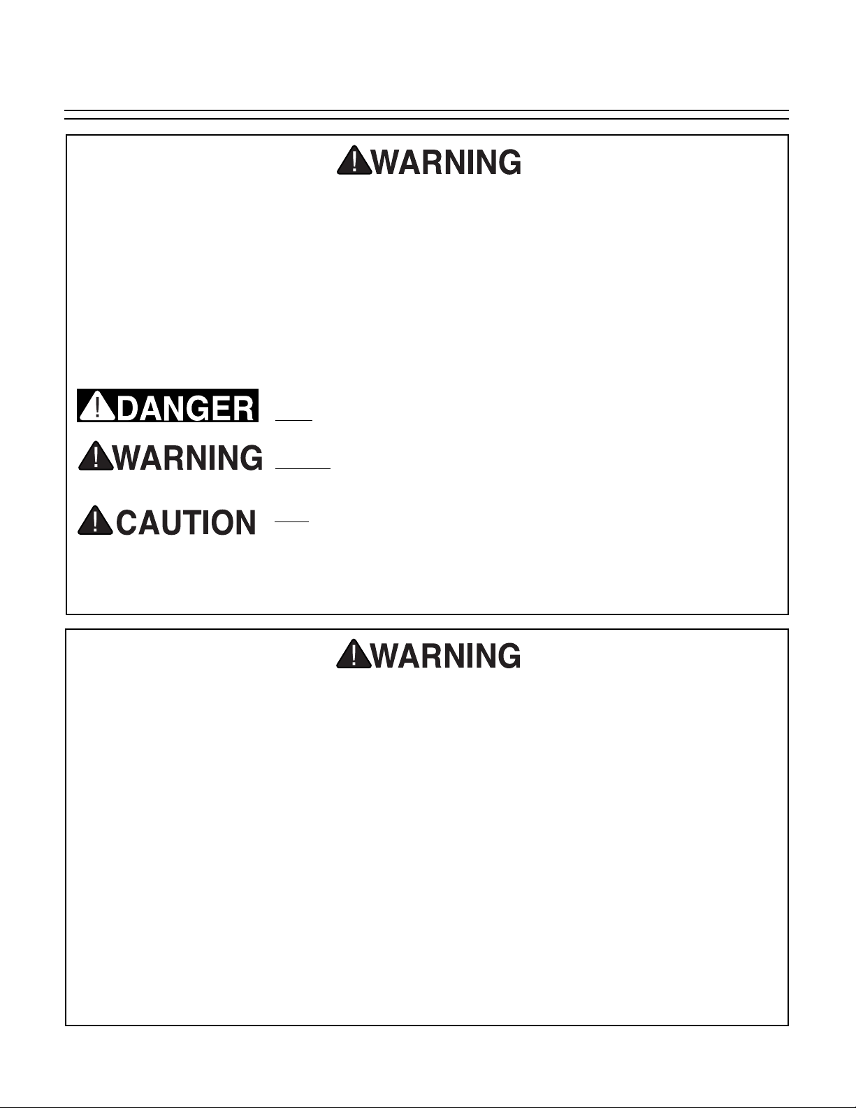
Indicates an imminently hazardous situation which, if not avoided,
WILL result in death or serious injury.
Indicates a potentially hazardous situation which, if not avoided,
COULD
result in death or serious injury.
Indicates a potentially hazardous situation which, if not avoided,
MAY
result in minor or moderate injury. It may also be used to alert
against unsafe practices.
This symbol is used to alert the user to useful information about
proper operation of the equipment.
The purpose of safety symbols is to attract your attention to possible hazardous conditions.
This manual uses a series of symbols and signal words which are intended to convey the level
of importance of the safety messages. The progression of symbols is described below.
Remember that safety messages by themselves do not eliminate danger and are not a substitute
for proper accident prevention measures.
NOTICE
Safety Instructions for Power Tools
For Your Own Safety Read Instruction
Manual Before Operating This Equipment
SECTION 1: SAFETY
Page 5
G7297 Disc Sander -3-
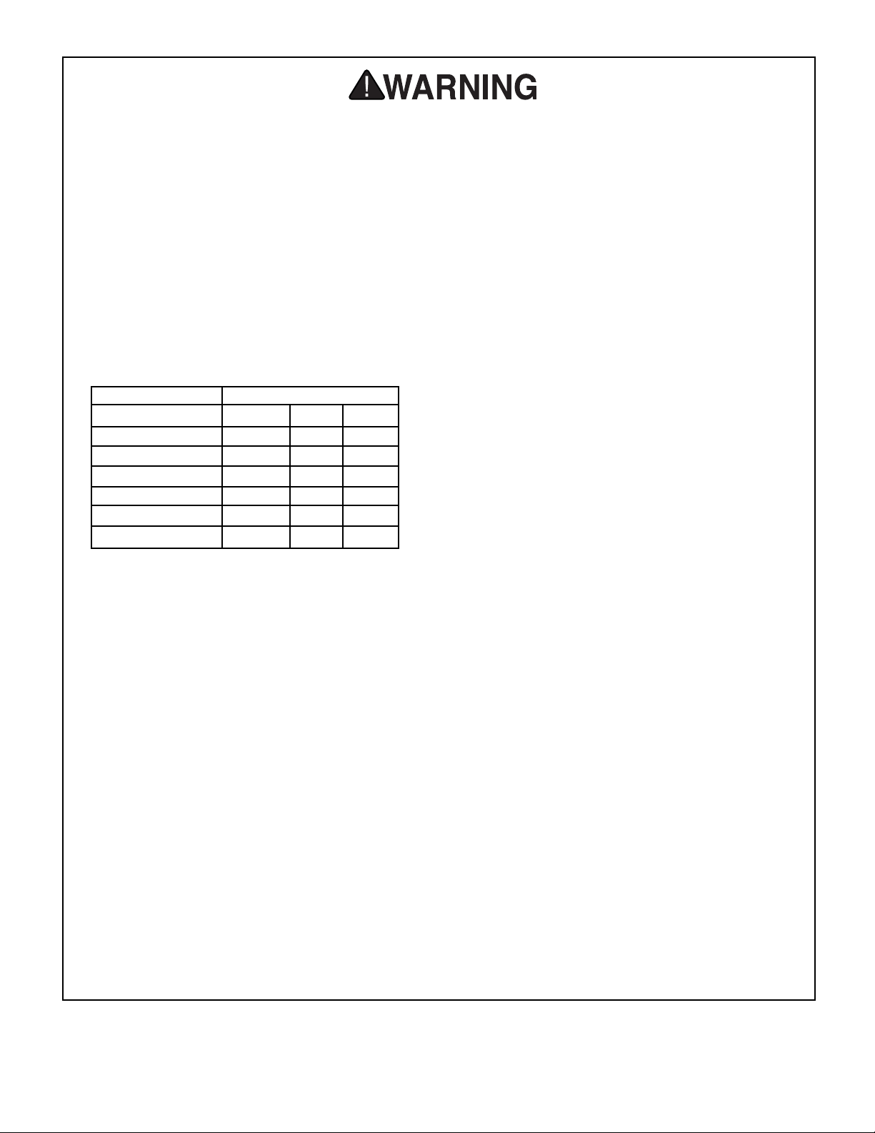
9. USE PROPER EXTENSION CORD. Make
sure your extension cord is in good condition. Conductor size should be in accordance with the chart below. The amperage
rating should be listed on the motor or tool
nameplate. An undersized cord will cause
a drop in line voltage resulting in loss of
power and overheating. Your extension
cord must also contain a ground wire and
plug pin. Always repair or replace extension cords if they become damaged.
Minimum Gauge for Extension Cords
10. WEAR PROPER APPAREL. DO NOT
wear loose clothing, gloves, neckties,
rings, bracelets, or other jewelry which may
get caught in moving parts. Non-slip
footwear is recommended. Wear protective
hair covering to contain long hair.
11. ALWAYS USE SAFETY GLASSES. Also
use face or dust mask if sanding operation is
dusty. Everyday eyeglasses only have impact
resistant lenses, they are NOT safety glasses.
12. SECURE WORK. Use clamps or a vise to hold
work when practical. It’s safer than using your
hand and frees both hands to operate tool.
13. DO NOT OVER-REACH. Keep proper
footing and balance at all times.
14. MAINTAIN TOOLS WITH CARE. Keep
tools sharp and clean for best and safest
performance. Follow instructions for lubricating and changing accessories.
LENGTH
AMP RATING 25ft 50ft 100ft
0-6 16 16 16
7-10 16 16 14
11-12 16 16 14
13-16 14 12 12
17-20 12 12 10
21-30 10 10 No
15. USE RECOMMENDED ACCESSORIES.
Consult the owner’s manual for recommended accessories. The use of improper
accessories may cause risk of injury.
16. REDUCE THE RISK OF UNINTENTIONAL STARTING. On machines with magnet-
ic contact starting switches there is a risk of
starting if the machine is bumped or jarred.
Always disconnect from power source
before adjusting or servicing. Make sure
switch is in OFF position before reconnecting.
17. CHECK DAMAGED PARTS. Before further use of the tool, a guard or other part
that is damaged should be carefully
checked to determine that it will operate
properly and perform its intended function.
Check for alignment of moving parts, binding of moving parts, breakage of parts,
mounting, and any other conditions that
may affect its operation. A guard or other
part that is damaged should be properly
repaired or replaced.
18. NEVER LEAVE TOOL RUNNING UNATTENDED. TURN POWER OFF. DO NOT
leave tool until it comes to a complete stop.
19. NEVER OPERATE A MACHINE WHEN
TIRED, OR UNDER THE INFLUENCE OF
DRUGS OR ALCOHOL. Full mental alert-
ness is required at all times when running a
machine.
20. NEVER ALLOW UNSUPERVISED OR
UNTRAINED PERSONNEL TO OPERATE THE MACHINE. Make sure any
instructions you give in regards to machine
operation are approved, correct, safe, and
clearly understood.
21. IF AT ANY TIME YOU ARE EXPERIENCING DIFFICULTIES performing the intend-
ed operation, stop using the machine! Then
contact our service department or ask a
qualified expert how the operation should
be performed.
Safety Instructions for Power Tools
Page 6
-4-
G7297 Disc Sander
1. BE AWARE OF DISC ROTATION when
sanding.
2. KEEP FINGERTIPS AWAY from the mov-
ing disc. Serious injury could result if skin
contacts abrasives or moving parts.
3. NEVER USE EXCESSIVE FORCE when
sanding. Doing this greatly increases the
chances of personal injury and motor overload.
4. ALWAYS FEED THE WORK against the
direction of rotation.
5. USE A DUST MASK or respirator when
sanding, as well as eye and ear protection,
even if you have a reliable method of dust
collection.
6. IF THERE IS ANY DOUBT ABOUT THE
STABILITY or integrity of the material to
be sanded, do not sand it.
7. DO NOT OPERATE SANDER with a dam-
aged or badly worn disc or belt.
8. WHEN DISC SANDING, feed material into
the portion of the disc spinning down
toward the table.
9. TIE BACK LONG HAIR and remove any
loose-fitting clothing or jewelry that could be
caught up in the sander’s disc, belt, or other
moving machine parts.
10. BE AWARE THAT CERTAIN WOODS
MAY CAUSE AN ALLERGIC REACTION
in people and animals, especially when
exposed to fine dust. Make sure you know
what type of wood dust you will be exposed
to and always wear an approved respirator.
11. HABITS — GOOD OR BAD — are hard to
break. Develop good habits and safety will
become second nature to you.
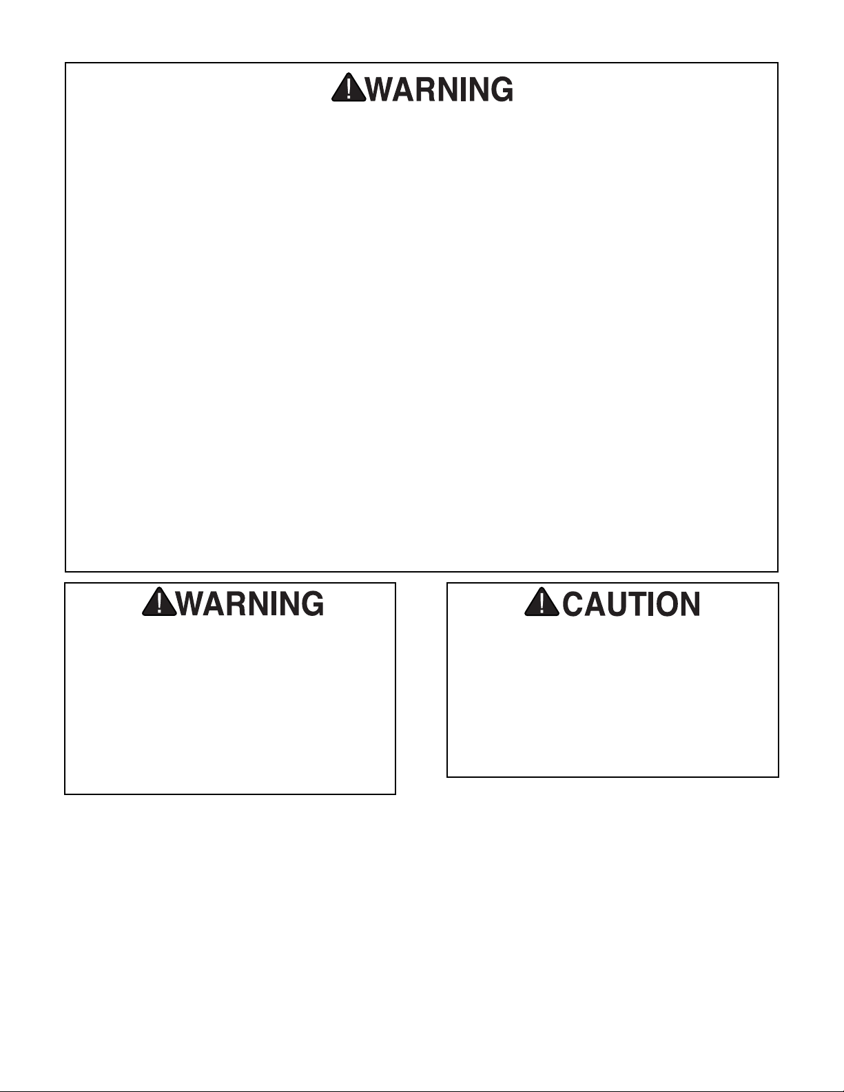
No list of safety guidelines can be complete. Every shop environment is different.
Always consider safety first, as it applies
to your individual working conditions. Use
this and other machinery with caution and
respect. Failure to do so could result in
serious personal injury, damage to equipment or poor work results.
Like all power tools, there is danger associated with the Model G7297 12" Disc
Sander. Accidents are frequently caused
by lack of familiarity or failure to pay attention. Use this tool with respect and caution to lessen the possibility of operator
injury. If normal safety precautions are
overlooked or ignored, serious personal
injury may occur.
Additional Safety Instructions for Sanders
Page 7
G7297 Disc Sander -5-
We are proud to offer the Model G7297 Disc
Sander. This 12" disc sander is a part of a growing Grizzly family of fine woodworking machinery.
When used according to the guidelines set forth
in this manual, you can expect years of troublefree, enjoyable operation and proof of Grizzly’s
commitment to customer satisfaction.
The Model G7297 Disc Sander features a 1 HP,
110V, 1725 RPM motor, a 12" sanding disc, a
17
1
⁄4" x 81⁄4" tilting cast aluminum table, a miter
gauge, and a built in 2" dust port. A number of
sanding disc grits for the Model G7297 Disc
Sander are available through the Grizzly catalog.
We are also pleased to provide this manual with
the Model G7297 Disc Sander. It was written to
guide you through assembly, review safety considerations, and cover general operating procedures. It represents our effort to produce the best
documentation possible.
If you have any comments regarding this manual,
please write to us at the address below:
Grizzly Industrial, Inc.
C
/O Technical Documentation
P.O. Box 2069
Bellingham, WA 98227-2069
Most importantly, we stand behind our machines.
If you have any service questions or parts
requests, please call or write us at the location
listed below.
Grizzly Industrial, Inc.
1203 Lycoming Mall Circle
Muncy, PA 17756
Phone: (570) 546-9663
Fax: (800) 438-5901
E-Mail: techsupport@grizzly.com
Web Site: http://www.grizzly.com
The specifications, drawings, and photographs
illustrated in this manual represent the Model
G7297 Disc Sander as supplied when the manual was prepared. However, owing to Grizzly’s policy of continuous improvement, changes may be
made at any time with no obligation on the part of
Grizzly. For your convenience, we always keep
current Grizzly manuals available on our website
at www.grizzly.com
. Any updates to your
machine will be reflected in these manuals as
soon as they are complete. Visit our site often to
check for the latest updates to this manual!
Read the manual before
assembly and operation.
Serious personal injury
may result if safety or
operational information
is not understood or followed.
SECTION 2: INTRODUCTION
Page 8
-6-
G7297 Disc Sander
Amperage Draw
The Model G7297 Disc Sander motor is wired to
operate at 110V and will draw the following load:
Motor Load............................................10 Amps
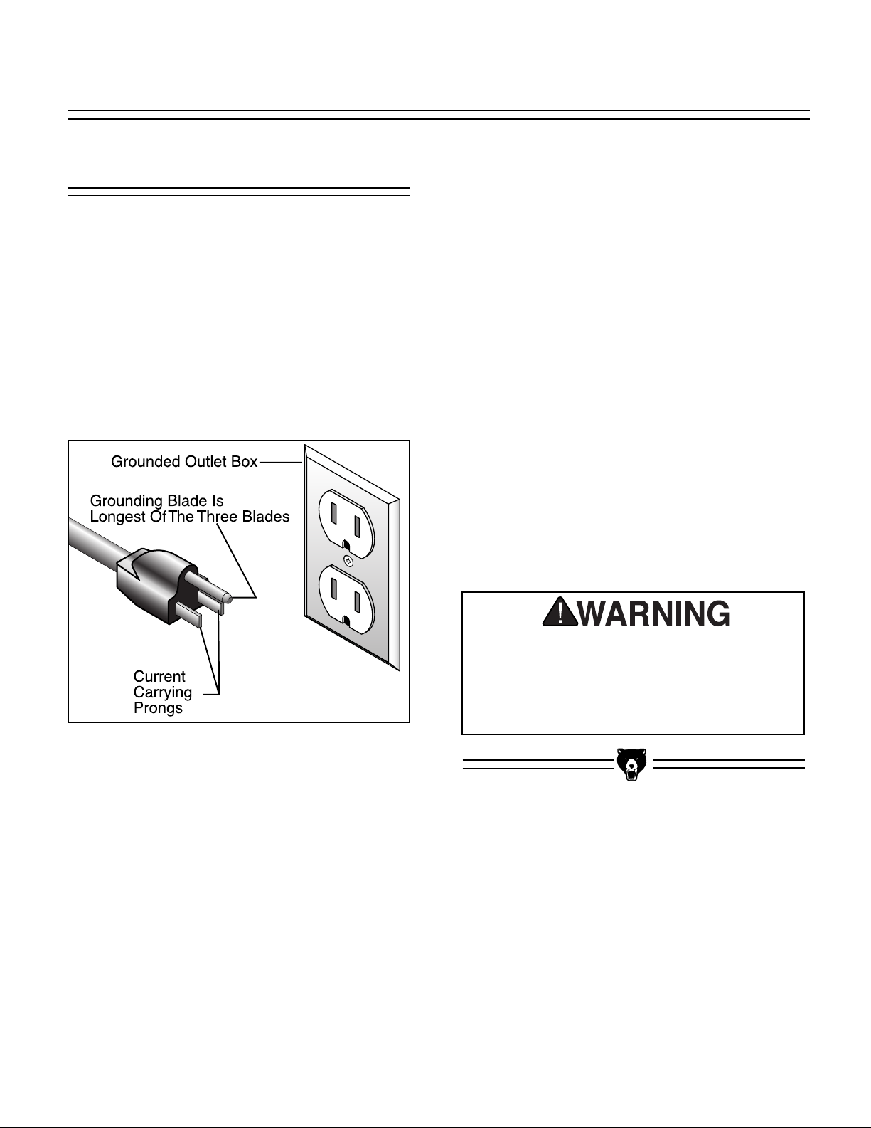
Plug Type
The Model G7297 Disc Sander is supplied with a
NEMA 5-15 plug. See Figure 1 for a NEMA 5-15
plug and grounded outlet. DO NOT modify the
plug or power cord in any way.
Circuit Breaker Requirements
We recommend that you dedicate a circuit to your
machine. Use the following guideline when
choosing a circuit breaker (circuit breakers rated
any higher are not adequate to protect the circuit):
Recommended Circuit Breaker ..............15 Amp
Your Circuit Capacity
Always check to see if the wires in your circuit are
capable of handling the amperage load from your
machine. If you are unsure, consult a qualified
electrician.
If you operate this machine on any circuit that is
already close to its load capacity, it may blow a
fuse or trip a circuit breaker. If the circuit is not
overloaded and the fuse or circuit breaker still
trips, contact a qualified electrician or our Service
Department at (570) 546-9663.
Serious personal injury could occur if you
connect your machine to the power source
before you have completed the assembly
process. DO NOT connect the machine to
the power source until instructed to do so.
Figure 1. NEMA 5-15 plug and
grounded outlet.
110 Volt Operation
SECTION 3: CIRCUIT REQUIREMENTS
Page 9
G7297 Disc Sander -7-
In the event of an electrical short, grounding
reduces the risk of electric shock by providing a
path of least resistance to disperse electric current. This tool is equipped with a power cord that
has an equipment-grounding prong. The outlet
must be properly installed and grounded in accordance with all local codes and ordinances.
110V Operation
If you find it necessary to use an extension cord
at 110V:
• Make sure the cord is rated Standard Service
(grade S) or better.
• The extension cord must also contain a
ground wire and plug pin.
• Use at least a 16 gauge cord if the cord is 50
feet long or less.
•DONOT use a cord longer that 100 feet!
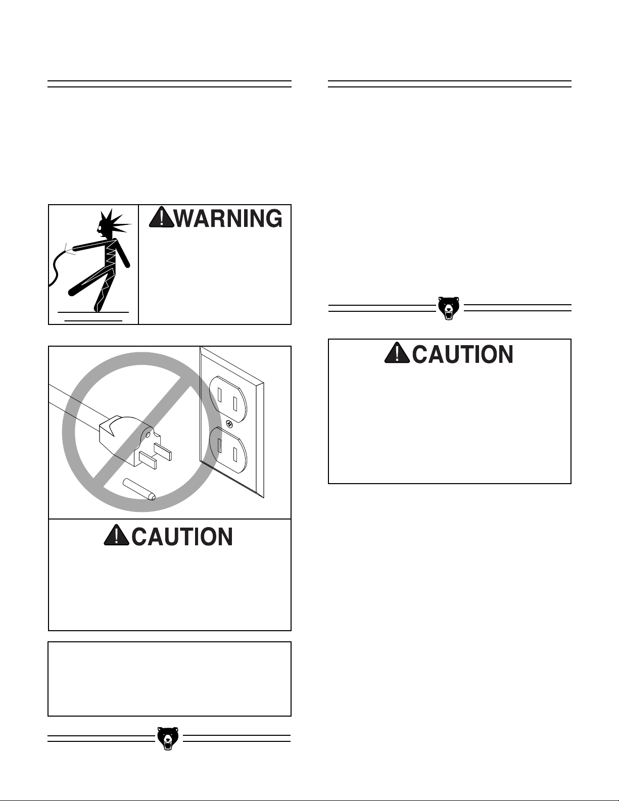
This machine must have a ground prong in
the plug to help ensure that it is grounded.
DO NOT remove ground prong from plug to
fit into a two-pronged outlet! If the plug will
not fit the outlet, have the proper outlet
installed by a qualified electrician.
Electrocution or a fire can
result if the machine is
not grounded correctly.
Make sure all electrical
circuits are grounded. DO
NOT use ungrounded
machines.
No single list of electrical guidelines can
be comprehensive for all shop environments. Operating this machinery may
require additional electrical upgrades specific to your machine and shop environment. It is your responsibility to make sure
your electrical systems comply with all
local electrical codes and ordinances.
NOTICE
The wire on the power cord with green or
green and yellow striped insulation is the
grounding conductor.
Extension CordsGrounding
Page 10

-8-
G7297 Disc Sander
The following is a list of controls and components on the Model G7297 Disc Sander. Please take time to
become familiar with each item and its location. These items will be used throughout the manual and knowing them is essential to understanding the instructions and terminology used in this manual.
1. Aluminum Disc (Sanding Disc Attached)
2. Disc Guard
3. Motor
4. ON/OFF Switch
5. Base
6. Dust Port (Opening Not Visible)
7. Miter Gauge
8. Work Table
2
1
3
4
5
7
6
8
SECTION 4: IDENTIFICATION
Page 11

G7297 Disc Sander -9-
Unpacking
• Motor and Disc Assembly ..........................1
•Miter Gauge................................................1
• 12" PSA Sanding Disc................................1
• Manual........................................................1
The machine is shipped from the manufacturer in
a carefully packed cardboard box. If you discover
the machine is damaged after you’ve signed for
delivery, and the truck and driver are gone, you
will need to file a freight claim with the carrier.
Save the containers and all packing materials for
possible inspection by the carrier or its agent.
Without the packing materials, filing a freight
claim can be difficult. If you need assistance
determining whether you need to file a freight
claim, or with the procedure to file one, please
contact our Customer Service.
When you are completely satisfied with the condition of your shipment, inventory its parts.
The Model G7297 Disc
Sander weighs 66 lbs.
Personal injury could
occur if the machine is
moved without additional assistance. Seek help
when moving or lifting
the machine.
Sharp edges on metal
parts may cause personal injury. Examine the
edges of all metal parts
before handling.
Figure 2. G7297 Inventory.
G7297 Inventory
SECTION 5: SET UP
Page 12

-10-
G7297 Disc Sander
Unsupervised children
and visitors inside your
shop could receive serious personal injury.
Ensure child and visitor
safety by keeping all
entrances to the shop
locked at all times. DO
NOT allow unsupervised
children or visitors in the
shop at any time.
Weight Load
The Model G7297 Disc Sander is a small weight
load with a small footprint. Most shop floors and
workbenches should be sufficient to carry the
weight of the machine. Reinforce the floor and
workbench if you question its ability to support the
weight.
Working Clearance
Working clearances can be thought of as the distances between machines and obstacles that
allow safe operation of every machine without
limitation. Consider existing and anticipated
machine needs, size of material to be processed
through each machine, and space for auxiliary
stands or work tables. Also consider the relative
position of each machine to one another for efficient material handling.
Lighting And Outlets
Lighting should be bright enough to eliminate
shadow and prevent eye strain. Electrical circuits
should be dedicated or large enough to handle
the amperage draw. Outlets should be located
near each machine so power or extension cords
are clear of high-traffic areas. Observe local electrical codes for proper installation of new lighting,
outlets, or circuits.
Site Considerations
Page 13

G7297 Disc Sander -11-
General
When the table tilt is set to 0˚, the table should be
adjusted perpendicular to the sanding disc face.
To adjust table tilt:
1. Using a try square or machinist’s square, set
one edge on the table surface and the other
against the face of the disc as shown in
Figure 3. Note—This can be done with the
sandpaper installed, although it is somewhat
easier to measure if the disc does not have
the sandpaper disc installed.
2. Loosen the lock lever and adjust the table
angle until it is perfectly perpendicular.
3. Tighten the lock lever while holding the table
perpendicular.
4. Adjust the stop bolt and tighten. Note—
Remove this bolt if you want to have the table
angle less than 90˚.
5. Move the table angle and return it to the 0˚
point using the indicator, then recheck with
the square to verify the setting.
Figure 3. Squaring disc table.
This section will cover the basic adjustment
instructions needed to begin operation. Complete
the adjustments provided in this manual and then
read the remaining portion of the manual before
attempting any type of operation.
Your safety is important! Please follow the
warnings below during this entire section:
Loose hair and clothing
could get caught in
machinery and cause
serious personal injury.
Keep loose clothing
rolled up and long hair
tied up and away from
machinery.
Serious personal injury
could occur if you connect your machine to the
power source before you
have completed the
assembly process. DO
NOT connect the
machine to the power
source until instructed to
do so.
Sharp edges on metal
parts may cause personal injury. Examine the
edges of all metal parts
before handling.
Tilt Indicator
Table Tilt
SECTION 6: ADJUSTMENTS
Page 14

-12-
G7297 Disc Sander
The Model G7297 Disc Sander accepts 12" diameter cloth or paper-backed PSA sanding discs.
These are available in a variety of grits. See the
current Grizzly catalog for prices and ordering
information.
The sanding disc sticks to the surface of the cast
iron disc, using the pressure sensitive adhesive
backing (PSA) on the reverse side of the sandpaper disc. The sandpaper can be replaced without removing either the table or the dust port.
To attach sandpaper:
1. Peel back the protective layer on one-half of
the sandpaper disc and fold it against the
remaining half.
2. Slip the half with the protective layer
between the disc and the table edge (Figure
5).
Figure 5. Sandpaper being slipped between the
disc and table.
The miter gauge needs to be adjusted perpendicular to the face of the wheel when it is mounted in
the table slot.
To adjust miter gauge:
1. Use a try square or machinist’s square with
one edge against the face of the miter gauge
and the other against the disc face as shown
in Figure 4.
2. Loosen the adjusting screw on the miter
gauge and adjust it flush with the edge of the
square.
3. Tighten the gauge adjusting screw, and veri-
fy the setting. Note—Sometimes the tighten-
ing procedure can affect the adjustment.
4. Loosen the screw that secures the angle
pointer and adjust the pointer to the 0˚ mark.
5. Retighten the screw that secures the angle
pointer.
Figure 4. Squaring miter gauge to disc.
Attaching SandpaperMiter Gauge
Page 15

G7297 Disc Sander -13-
Figure 6. Removing protective layer.
Figure 7. Table aligned with sanding disc.
The table must be aligned to the face of the sanding disc so that the sandpaper does not rub
against the table.
To align the table:
1. Loosen the screws that secure the table to
the table support bracket.
2. Align the table so that there is a
1
⁄16'' gap
between the 12" disc and the table (Figure
7).
3. Tighten the screws loosened in step 1.
4. Spin the disc by hand to check if the sand-
paper is touching the table. Note—DO NOT
turn the disc sander on at this point.
5. Repeat steps 1-3 if sandpaper touches table
at any point in the rotation.
3. Position the exposed adhesive on the upper
half of the disc that extends above the table.
Once it is positioned evenly across the disc,
press the adhesive onto the surface.
4. Now rotate the disc so the lower half is now
above the table.
5. Bend the paper back and remove the
remaining half of the protective layer (Figure
6), and then press this portion against the
disc.
Aligning Table
1⁄16 Gap
Table Support
Screws
Page 16

Damage to your eyes, lungs, and ears
could result from failure to wear safety
glasses, a dust mask, and hearing protection while sanding with this machine.
Loose hair and clothing
could get caught in
machinery and cause
serious personal injury.
Keep loose clothing
rolled up and long hair
tied up and away from
machinery.
This section will cover basic disc sanding operations. Please read the remaining portion of the
manual before attempting any type of operation.
Your safety is important! Please follow the
warnings below during this entire section:
-14-
G7297 Disc Sander
Operating this equipment has the potential
to propel debris into the air which can
cause eye injury. Always wear safety glasses or goggles when operating equipment.
Everyday glasses or reading glasses only
have impact resistant lenses, they are not
safety glasses. Be certain the safety glasses you wear meet the appropriate standards of the American National Standards
Institute (ANSI).
To perform sanding operations:
1. Set the angle of the table relative to the
sanding disc. The angle can be set with the
angle gauge on the disc sander or with a protractor for greater accuracy.
2. When a 90˚ horizontal angle is required,
place one surface of the workpiece firmly
against the face of the miter gauge (set at
0˚), with the other surface against the face of
the disc (Figure 8).
Note—For sanding curves or irregular shapes,
remove the miter gauge from the disc table.
Always keep the workpiece on the side of the
wheel that is rotating down toward the table. This
will keep the workpiece from flying out of your
hands from the rotational forces.
Figure 8. Disc sanding.
General
Disc Sanding
SECTION 7: OPERATIONS
Page 17

G7297 Disc Sander -15-
The most efficient way to get a perfect miter is to
cut the workpiece slightly long and sand it to the
desired dimension. Miter sanding can be done
easily with the miter gauge:
To perform miter sanding operations:
1. Loosen the knob on the miter gauge and
adjust the angle to the desired point. Tighten
the knob.
2. Slide the miter gauge into its slot and use it
to hold your workpiece in position. Note—
The miter gauge can be used in either direction in the slot to achieve the proper relation
of the workpiece to the disc.
3. With light, but firm pressure, push the work-
piece slowly into the downspin side of the
rotating disc (Figure 9).
Figure 9. Mitering with gauge angled.
Rotation
To perform angle sanding operations:
1. Loosen the handles securing the table.
2. Use the angle gauge to acheive the desired
table angle and tighten the handles. Note—
The disc table can be positioned from -15˚ to
35˚, relative to the plane of the sanding surface. Whenever possible, sand with an open
angle where there is plenty of clearance
between the disc and the table. This will
avoid trapping the workpiece between the
sanding surface and the table.
3. Slide the miter gauge into its slot and use it
to hold your workpiece in position.
4. With light, but firm pressure, push the work-
piece slowly into the downspin side of the
rotating disc (Figure 10).
Figure 10. Mitering with table angled.
Rotation
Angle SandingMiter Sanding
Page 18

-16-
G7297 Disc Sander
Loose hair and clothing
could get caught in
machinery and cause
serious personal injury.
Keep loose clothing
rolled up and long hair
tied up and away from
machinery.
Projectiles from the
machine could cause
serious eye injury.
Wear safety glasses at
all times.
Serious personal injury
could occur if you connect your machine to the
power source during the
maintenance process.
DO NOT connect the
machine to the power
source while performing
any maintenance on this
machine.
Your safety is important! Please follow the
warnings below during this entire section:
Following a maintainance schedule ensures that
your machine is safe and performs accurately.
Check the following items before you use the
disc sander:
• Loose mounting bolts.
• Worn loose, or damaged sanding
disc.
• Worn or damaged wires.
• Any other condition that could hamper
the safe operation of this machine.
Perform the following tasks at the scheduled
time intervals:
After Each Use
• Wipe off the sawdust build-up from
the table surface.
Weekly
• Wipe a lubricant such as SLIPIT
®
onto
the table.
Long-Term Storage
• Keep unpainted surfaces rust free
with products such as Boeshield
®
T-9.
Schedule
Maintenance Safety
SECTION 8: MAINTENANCE
Page 19

G7297 Disc Sander -17-
This section contains the following subsections
for the Model G7297 Disc Sander: aftermarket
accessories, data sheets, wiring diagrams, parts
diagrams and list, troubleshooting, and
warranty/return information.
If you need parts or help in assembling your
machine, or if you need operational information,
call the service department at (570) 546-9663.
Trained service technicians will be glad to help
you.
General
The following aftermarket accessories can be
ordered from the Grizzly Catalog by calling (800)
523-4777, or by visiting www.grizzly.com.
12" PSA Sanding Discs
MODEL DESCRIPTION
G1220....................................................60 Grit
G4255....................................................80 Grit
G1221..................................................100 Grit
G4256..................................................120 Grit
G1222..................................................150 Grit
G4257..................................................100 Grit
G4258..................................................220 Grit
Aftermarket
Accessories
SECTION 9: REFERENCE INFO
Page 20

-18-
G7297 Disc Sander
Disconnect power to the
machine when performing any maintenance or
repairs. Failure to do this
may result in serious
personal injury.
SYMPTOM
Motor will not start;
fuses or circuit breakers blow.
Motor fails to develop
full power (power output of motor decreases rapidly with
decrease in voltage at
motor terminals).
Motor overheats,
slows, or stalls
(resulting in blown
fuses or tripped circuit).
Sanded surface not
square.
POSSIBLE CAUSE
1. No voltage.
2. Incorrect fuses or circuit
breakers in power line.
3. Bad wiring in motor, or
faulty start capacitor.
4. Short circuit in line cord or
plug.
1. Circuit is overloaded.
2. Start capacitor is faulty
3. Undersized wires or circuits too long.
1. Motor overloaded.
2. Air circulation through the
motor restricted.
3. Short circuit in motor or
loose connections.
4. Low voltage.
5. Incorrect fuses or circuit
breakers in power line.
1. Table not perpendicular to
disc.
2. Miter gauge not square to
disc.
CORRECTIVE ACTION
1. Check for tripped fuse or breaker.
2. Install correct fuses or circuit breakers.
3. Inspect all connections on motor for
loose or shorted terminals, replace
start capacitor.
4. Inspect cord or plug for damaged insulation and shorted wires.
1. Reduce load on circuit, or use dedicated circuit.
2. Replace start capacitor.
3. Increase wire sizes or reduce length of
wire.
1. Reduce load on motor, feed workpiece
slower
2. Clean out motor to provide normal air
circulation.
3. Inspect connections on motor for
loose or shorted terminals.
4 Correct the low voltage conditions.
5. Install correct fuses or circuit breakers.
1. Adjust table tilt.
2. Adjust miter gauge.
TROUBLESHOOTING GUIDE
Page 21

G7297 Disc Sander -19-
Design Type.................................................................................................... Bench Model
Overall Dimensions and Specifications:
Height ..................................................................................................................14
1
⁄2''
Width ....................................................................................................................17
3
⁄8
''
Length ......................................................................................................................18''
Table ..........................................................................................................17
1
⁄4'' x 81⁄4''
Weight ................................................................................................................66 lbs.
Box Size......................................................................................18" L x 17" W x 17" H
Footprint ..........................................................................................................13" x 10"
Features:
Aluminum Disc..........................................................................................................12''
Aluminum Disc Speed ..................................................................................1750 RPM
Miter Gauge Groove..........................................................................................
3
⁄
8'' x
3
⁄
4''
Miter Gauge......................................................................................Plastic ⁄ Aluminum
Table Tilt Range ......................................................................................................45°
Construction:
Base ................................................................................................................Cast Iron
Table ............................................................................................................Aluminum
Motor:
Type ............................................................................................TEFC Capacitor Start
Horsepower............................................................................................................1 HP
Phase ⁄ Voltage ............................................................................Single Phase ⁄ 110V
Amperage ..................................................................................................................10
Cycle and RPM ............................................................................60 Hertz ⁄ 1750 RPM
Switch ..........................................................................................Keyed Safety Switch
Power Transfer ..........................................................................................Direct Drive
Bearings ....................................................................Sealed, Permanently Lubricated
Features:
..................................................................................................................2'' Dust Port
..........................................................................................................Locking Miter Bar
..................................................................................................Accepts 12" PSA Discs
..............................................................................Large Tilting Cast Aluminum Table
Specifications, while deemed accurate, are not guaranteed.
Customer Service #: (570) 546-9663 • To Order Call: (800) 523-4777 • Fax #: (800) 438-5901
GRIZZLY MODEL G7297 12" DISC SANDER
MACHINE DATA
SHEET
Page 22

-20- G7297 Disc Sander
45
Read manual for important
safety instructions before
operating this equipment.
64
58
31
65
46
12
48
47
67
49
57
14
53
67
66
8
51
54
33
32
13
36
35
50
55
34
2
9
10
63
19
21
37
43A
38
42
24
29
18
22
30
24
28
23
0
27
20
26
25
62
1
3
4
29
39
21
60
ALW
EYE P
AYS W
RO
EA
TE
R
CTION
43
21
41
19
Page 23

058 P7297058 NAME PLATE
060 P7297060 ROTATION ARROW
062 P7297062 WAVY WASHER 39MM
063 P7297063 MOTOR 1HP
064 P7297064 READ MANUAL
065 P7297065 DUST WARNING
066 PLW01M LOCK WASHER 5MM
067 PTLW06M EXT TOOTH WSHR 4MM
001 G4255 80 GRIT SANDING DISC
002 P7297002 BASE
003 P6204 BEARING 6204
004 PK23M KEY M5 X 5 X 25
008 PC100A CAPACITOR 100MFD/250V
009 PS07M PHLP HD SCR M4-0.7 X 8
010 P7297010 CAPACITOR BOX
012 P7297012 FAN COVER
013 PS07M PHLP HD SCR M4-0.7 X 8
014 P7297014 FAN
015 PS06M PHLP HD SCR M5-0.8 X 20
018 PS47M PHLP HD SCR M6-1.0 X 25
019 P7297019 TABLE LOCK
020 P7297020 ADJUSTING PIN
021 PW03M FLAT WASHER 6MM
022 P7297022 RUBBER PAD
023 PN01M HEX NUT M6-1.0
024 PW03M FLAT WASHER 6MM
025 P7297025 SANDING DISC
026 P7297026 SPCL WSR
1
⁄4"ID X 1-1⁄4"OD
027 PS26M PHLP HD SCR M6-1.0 X 20
028 P7297028 DUST CHUTE COVER
029 PLW03M LOCK WASHER 6MM
030 PS26M PHLP HD SCR M6-1.0 X 20
031 P7297031 REFERENCE LABEL
032 PS19M PHLP HD SCR M5-0.8 x 6.
033 P7297033 ANGLE POINTER
034 P7297034 KNOB BOLT M6-0.1 X 22
035 PW03M FLAT WASHER 6MM
036 P7297036 MITER GAUGE
036A P7297036 COMPLETE MITER GA
037 P7297037 GAUGE SLIDE
038 P7297038 PIN M5 X 12
039 PN01M HEX NUT M6-1.0
041 P7297041 WORK TABLE
042 PFH06M FLAT HD SCR M6-1.0 X 20
043 P7297043 LEFT TRUNNION
043A P7297043 RIGHT TRUNNION
045 P7297045 SWITCH LOCK
046 PSW06 SWITCH 110/220V
047 PS17M PHLP HD SCR M4-0.7 x 6
048 P7297048 SWITCH PLATE
049 P7297049 CORD & PLUG
050 PTLW02M EXT TOOTH WSHR 5MM
051 PS09M PHLP HD SCR M5-0.8 X 10
053 PS09M PHLP HD SCR M5-0.8 X 10
054 P7297054 WIRING BOX
055 P7297055 GROUND INDICATOR
057 PW05M FLAT WASHER 4MM
G7297 Disc Sander -21-
REF PART # DESCRIPTION REF PART # DESCRIPTION
Page 24

-22-
G7297 Disc Sander
Grizzly Industrial, Inc. warrants every product it sells for a period of 1 year to the original purchaser from
the date of purchase. This warranty does not apply to defects due directly or indirectly to misuse, abuse,
negligence, accidents, repairs or alterations or lack of maintenance. This is Grizzly’s sole written warranty
and any and all warranties that may be implied by law, including any merchantability or fitness, for any particular purpose, are hereby limited to the duration of this written warranty. We do not warrant or represent
that the merchandise complies with the provisions of any law or acts unless the manufacturer so warrants.
In no event shall Grizzly’s liability under this warranty exceed the purchase price paid for the product and
any legal actions brought against Grizzly shall be tried in the State of Washington, County of Whatcom.
We shall in no event be liable for death, injuries to persons or property or for incidental, contingent, special, or consequential damages arising from the use of our products.
To take advantage of this warranty, contact us by mail or phone and give us all the details. We will then
issue you a “Return Number,’’ which must be clearly posted on the outside as well as the inside of the carton. We will not accept any item back without this number. Proof of purchase must accompany the merchandise.
The manufacturers reserve the right to change specifications at any time because they constantly strive to
achieve better quality equipment. We make every effort to ensure that our products meet high quality and
durability standards and we hope you never need to use this warranty.
Please feel free to write or call us if you have any questions about the machine or the manual.
Thank you again for your business and continued support. We hope to serve you again soon.
Warranty and Returns
Page 25

G7297 Disc Sander -23-
CUT ALONG DOTTED LINE
9. How many of your woodworking machines are Grizzly? _____________
10. Which benchtop tools do you own? Check all that apply.
___1" x 42" Belt Sander ___6" - 8" Grinder
___5" - 8" Drill Press ___Mini Lathe
___8" Table Saw ___10" - 12" Thickness Planer
___8" - 10" Bandsaw ___Scroll Saw
___Disc/Belt Sander ___Spindle/Belt Sander
___Mini Jointer
___Other__________________________________________________
11. How many of the machines checked above are Grizzly? ____________
12. Which portable/hand held power tools do you own? Check all that apply.
___Belt Sander ___Orbital Sander
___Biscuit Joiner ___Palm Sander
___Circular Saw ___Portable Planer
___Detail Sander ___Saber Saw
___Drill/Driver ___Reciprocating Saw
___Miter Saw ___Router
___Other__________________________________________________
13. What machines/supplies would you like Grizzly Industrial to carry?
__________________________________________________________
__________________________________________________________
14. What new accessories would you like Grizzly Industrial to carry?
__________________________________________________________
__________________________________________________________
15. What other companies do you purchase your tools and supplies from?
__________________________________________________________
__________________________________________________________
16. Do you think your purchase represents good value?
___Yes ___No
17. Would you recommend Grizzly Industrial to a friend?
___Yes ___No
18. Would you allow us to use your name as a reference for Grizzly customers
in your area? Note: We never use names more than three times.
___Yes ___No
19. Comments:_________________________________________________
__________________________________________________________
__________________________________________________________
__________________________________________________________
__________________________________________________________
1. How did you learn about us?
___Advertisement ___Friend
___Catalog ___Card Deck
___World Wide Web
___Other__________________________________________________
2. Which of the following magazines do you subscribe to.
___American Woodworker ___Practical Homeowner
___Cabinetmaker ___Shop Notes
___Family Handyman ___Today’s Homeowner
___Fine Homebuilding ___WOOD
___Fine Woodworking ___Wooden Boat
___Home Handyman ___Woodshop News
___Journal of Light Construction ___Woodsmith
___Old House Journal ___Woodwork
___Popular Mechanics ___Woodworker
___Popular Science ___Woodworker’s Journal
___Popular Woodworking ___Workbench
___Other__________________________________________________
3. Which of the following woodworking/remodeling shows do you watch?
___Backyard America ___The New Yankee Workshop
___Home Time ___This Old House
___The American Woodworker ___Woodwright’s Shop
___Other__________________________________________________
4. What is your annual household income?
___$20,000-$29,999 ___$60,000-$69,999
___$30,000-$39,999 ___$70,000-$79,999
___$40,000-$49,999 ___$80,000-$89,999
___$50,000-$59,999 ___$90,000 +
5. What is your age group?
___20-29 ___50-59
___30-39 ___60-69
___40-49 ___70 +
6. How long have you been a woodworker?
___0 - 2 Years ___8 - 20 Years
___2 - 8 Years ___20+ Years
7. How would you rank your woodworking skills?
___Simple ___Advanced
___Intermediate ___Master Craftsman
8. What stationary woodworking tools do you own? Check all that apply.
___Air Compressor ___Panel Saw
___Bandsaw ___Planer
___Drill Press ___Power Feeder
___Drum Sander ___Radial Arm Saw
___Dust Collector ___Shaper
___Horizontal Boring Machine ___Spindle Sander
___Jointer ___Table Saw
___Lathe ___Vacuum Veneer Press
___Mortiser ___Wide Belt Sander
___Other__________________________________________________
Name ____________________________________________________________________________________
Street ____________________________________________________________________________________
City ______________________________________________________________State________Zip_________
Phone Number_______________________E-Mail_______________________FAX________________________
MODEL #_____________________Serial # __________________________ Order #______________________
The following information is given on a voluntary basis. It will be used for marketing purposes to help us develop better products and services. Of
course, all information is strictly confidential.
WARRANTY CARD
Page 26

FOLD ALONG DOTTED LINE
FOLD ALONG DOTTED LINE
GRIZZLY INDUSTRIAL, INC.
P.O. BOX 2069
BELLINGHAM, WA 98227-2069
Place
Stamp
Here
TAPE ALONG EDGES--PLEASE DO NOT STAPLE
Name_______________________________
Street_______________________________
City______________State______Zip______
Send a Grizzly Catalog to a friend:
Page 27

Buy Direct and Save with Grizzly® – Trusted, Proven and a Great Value!
Visit Our Website Today And Discover Why
Grizzly® Is The Industry Leader!
• SECURE ORDERING
• ORDERS SHIPPED WITHIN 24 HOURS
• E-MAIL RESPONSE WITHIN ONE HOUR
-OR-
Call Today For A
Full Color Catalog
FREE
 Loading...